Description of the operating principle and device
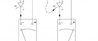
The main difference between these elements and thyristors is the bidirectional conductivity of electric current. Essentially, these are two SCRs with common control, connected back-to-back (see A in Fig. 1).
Rice. 1. Circuit with two thyristors, as an equivalent of a triac, and its conventional graphic designation
This gave the name to the semiconductor device, as a derivative of the phrase “symmetrical thyristors” and was reflected in its UGO. Let us pay attention to the designations of the terminals, since current can be carried in both directions, the designation of the power terminals as Anode and Cathode does not make sense, therefore they are usually designated as “T1” and “T2” (options TE1 and TE2 or A1 and A2 are possible). The control electrode is usually designated “G” (from the English gate).
Now consider the structure of the semiconductor (see Fig. 2.) As can be seen from the diagram, there are five junctions in the device, which allows you to organize two structures: p1-n2-p2-n3 and p2-n2-p1-n1, which, in fact, are two counter-current thyristors connected in parallel.
Rice. 2. Block diagram of a triac
When negative polarity is formed at the power terminal T1, the trinistor effect begins to manifest itself in p2-n2-p1-n1, and when it changes, p1-n2-p2-n3.
Concluding the section on the principle of operation, we present the current-voltage characteristics and the main characteristics of the device.
I-V characteristics of the triac
Designation:
- A – closed state.
- B – open state.
- UDRM (UPR) – maximum permissible voltage level for direct connection.
- URRM (UOB) – maximum reverse voltage level.
- IDRM (IPR) – permissible direct current level
- IRRM (IOB) - permissible level of reverse switching current.
- IN (IUD) – holding current values.
Peculiarities
To have a complete understanding of symmetrical thyristors, it is necessary to talk about their strengths and weaknesses. The first include the following factors:
- relatively low cost of devices;
- long service life;
- lack of mechanics (that is, moving contacts that are sources of interference).
The disadvantages of the devices include the following features:
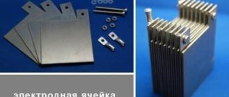
- The need for heat removal is approximately at the rate of 1-1.5 W per 1 A, for example, at a current of 15 A, the power dissipation value will be about 10-22 W, which will require an appropriate radiator. For ease of fastening to it for powerful devices, one of the terminals has a thread for a nut.
Triac with radiator mount
- Devices are subject to transients, noise and interference;
- High switching frequencies are not supported.
The last two points require a little clarification. In the case of high switching speed, there is a high probability of spontaneous activation of the device. Interference in the form of a voltage surge can also lead to this result. To protect against interference, it is recommended to bypass the device with an RC circuit.
RC circuit to protect the triac from interference
In addition, it is recommended to minimize the length of the wires leading to the controlled output, or alternatively use shielded conductors. It is also practiced to install a shunt resistor between the T1 terminal (TE1 or A1) and the control electrode.
Main characteristics of triacs, thyristors, dinistors manufactured by Philips
| Name | Voltage in close comp. max., V | Opening current max., mA | Current in open state max., A | Type of shell |
| BT131-600 | 600 | 3 | 1 | SOT-54 (SPT, E-1) |
| BT134-600D | 600 | 5 | 4 | SOT-82 |
| BT134-600E | 600 | 10 | 4 | SOT-82 |
| BT134-800E | 800 | 10 | 4 | SOT-82 |
| BT134W-600 | 600 | 35 | 1 | SOT-223 (SC-73) |
| BT134W-600D | 600 | 5 | 1 | SOT-223 (SC-73) |
| BT134W-600E | 600 | 10 | 1 | SOT-223 (SC-73) |
| BT134W-800 | 800 | 35 | 1 | SOT-223 (SC-73) |
| BT136-600D | 600 | 5 | 4 | SOT-78 (TO-220AB, SC-46) |
| BT136-600E | 600 | 10 | 4 | SOT-78 (TO-220AB, SC-46) |
| BT136-800E | 800 | 10 | 4 | SOT-78 (TO-220AB, SC-46) |
| BT136B-600E | 600 | 10 | 4 | SOT-404 (D2-PAK) |
| BT136B-800E | 800 | 10 | 4 | SOT-404 (D2-PAK) |
| BT136S-600 | 600 | 35 | 4 | SOT-428 (SC-63, D-PAK) |
| BT136S-600D | 600 | 5 | 4 | SOT-428 (SC-63, D-PAK) |
| BT136S-600E | 600 | 10 | 4 | SOT-428 (SC-63, D-PAK) |
| BT136S-600F | 600 | 25 | 4 | SOT-428 (SC-63, D-PAK) |
| BT136S-800 | 800 | 35 | 4 | SOT-428 (SC-63, D-PAK) |
| BT136S-800E | 800 | 10 | 4 | SOT-428 (SC-63, D-PAK) |
| BT136S-800F | 800 | 25 | 4 | SOT-428 (SC-63, D-PAK) |
| BT136X-600 | 600 | 35 | 4 | SOT-186A (TO-220F) |
| BT136X-600D | 600 | 5 | 4 | SOT-186A (TO-220F) |
| BT136X-600E | 600 | 10 | 4 | SOT-186A (TO-220F) |
| BT136X-600F | 600 | 25 | 4 | SOT-186A (TO-220F) |
| BT136X-800 | 800 | 35 | 4 | SOT-186A (TO-220F) |
| BT136X-800E | 800 | 10 | 4 | SOT-186A (TO-220F) |
| BT137-600D | 600 | 5 | 8 | SOT-78 (TO-220AB, SC-46) |
| BT137-600E | 600 | 10 | 8 | SOT-78 (TO-220AB, SC-46) |
| BT137-800E | 800 | 10 | 8 | SOT-78 (TO-220AB, SC-46) |
| BT137B-600E | 600 | 10 | 8 | SOT-404 (D2-PAK) |
| BT137B-600F | 600 | 25 | 8 | SOT-404 (D2-PAK) |
| BT137B-800 | 800 | 35 | 8 | SOT-404 (D2-PAK) |
| BT137B-800E | 800 | 10 | 8 | SOT-404 (D2-PAK) |
| BT137B-800F | 800 | 25 | 8 | SOT-404 (D2-PAK) |
| BT137S-600 | 600 | 35 | 8 | SOT-428 (SC-63, D-PAK) |
| BT137S-600D | 600 | 5 | 8 | SOT-428 (SC-63, D-PAK) |
| BT137S-600E | 600 | 10 | 8 | SOT-428 (SC-63, D-PAK) |
| BT137S-600F | 600 | 25 | 8 | SOT-428 (SC-63, D-PAK) |
| BT137S-800 | 800 | 35 | 8 | SOT-428 (SC-63, D-PAK) |
| BT137S-800E | 800 | 10 | 8 | SOT-428 (SC-63, D-PAK) |
| BT137S-800F | 800 | 25 | 8 | SOT-428 (SC-63, D-PAK) |
| BT137X-600 | 600 | 35 | 8 | SOT-186A (TO-220F) |
| BT137X-600D | 600 | 5 | 8 | SOT-186A (TO-220F) |
| Name | Voltage in close comp. max., V | Opening current max., mA | Current in open state max., A | Type of shell |
| BT137X-600E | 600 | 10 | 8 | SOT-186A (TO-220F) |
| BT137X-600F | 600 | 25 | 8 | SOT-186A (TO-220F) |
| BT137X-800 | 800 | 35 | 8 | SOT-186A (TO-220F) |
| BT137X-800E | 800 | 10 | 8 | SOT-186A (TO-220F) |
| BT138-600E | 600 | 10 | 12 | SOT-78 (TO-220AB, SC-46) |
| BT138-800E | 800 | 10 | 12 | SOT-78 (TO-220AB, SC-46) |
| BT138B-600 | 600 | 35 | 12 | SOT-404 (D2-PAK) |
| BT138B-600E | 600 | 10 | 12 | SOT-404 (D2-PAK) |
| BT138B-600F | 600 | 25 | 12 | SOT-404 (D2-PAK) |
| BT138B-800E | 800 | 10 | 12 | SOT-404 (D2-PAK) |
| BT138X-600 | 600 | 35 | 12 | SOT-186A (TO-220F) |
| BT138X-600E | 600 | 10 | 12 | SOT-186A (TO-220F) |
| BT138X-600F | 600 | 25 | 12 | SOT-186A (TO-220F) |
| BT138X-800 | 800 | 35 | 12 | SOT-186A (TO-220F) |
| BT138X-800E | 800 | 10 | 12 | SOT-186A (TO-220F) |
| BT138X-800F | 800 | 25 | 12 | SOT-186A (TO-220F) |
| BT139-600E | 600 | 10 | 16 | SOT-78 (TO-220AB, SC-46) |
| BT139-800E | 800 | 10 | 16 | SOT-78 (TO-220AB, SC-46) |
| BT139B-600 | 600 | 35 | 16 | SOT-404 (D2-PAK) |
| BT139B-600E | 600 | 10 | 16 | SOT-404 (D2-PAK) |
| BT139B-600F | 600 | 25 | 16 | SOT-404 (D2-PAK) |
| BT139B-800 | 800 | 35 | 16 | SOT-404 (D2-PAK) |
| BT139B-800E | 800 | 10 | 16 | SOT-404 (D2-PAK) |
| BT139B-800F | 800 | 25 | 16 | SOT-404 (D2-PAK) |
| BT139X-600 | 600 | 35 | 16 | SOT-186A (TO-220F) |
| BT139X-600E | 600 | 10 | 16 | SOT-186A (TO-220F) |
| BT139X-600F | 600 | 25 | 16 | SOT-186A (TO-220F) |
| BT139X-800 | 800 | 35 | 16 | SOT-186A (TO-220F) |
| BTA140-600 | 600 | 35 | 25 | SOT-78 (TO-220AB, SC-46) |
| BTA140-800 | 800 | 35 | 25 | SOT-78 (TO-220AB, SC-46) |
| MAC97A6 | 400 | 5 | 0.6 | SOT-54 (SPT, E-1) |
| MAC97A8 | 600 | 5 | 0.6 | SOT-54 (SPT, E-1) |
| Z0103MA | 600 | 3 | 1 | SOT-54B |
| Z0103MN | 600 | 3 | 1 | SOT-223 (SC-73) |
| Z0103NA | 800 | 3 | 1 | SOT-54B |
| Z0103NN | 800 | 3 | 1 | SOT-223 (SC-73) |
| Z0107MA | 600 | 5 | 1 | SOT-54B |
| Z0107MN | 600 | 5 | 1 | SOT-223 (SC-73) |
| Z0107NA | 800 | 5 | 1 | SOT-54B |
| Z0107NN | 800 | 5 | 1 | SOT-223 (SC-73) |
| Z0109MA | 600 | 10 | 1 | SOT-54B |
| Z0109MN | 600 | 10 | 1 | SOT-223 (SC-73) |
| Z0109NA | 800 | 10 | 1 | SOT-54B |
| Z0109NN | 800 | 10 | 1 | SOT-54B |
Triacs and thyristors dinistors BT, main characteristics, analogues and pinout
on Vremont.su
Application
This type of semiconductor elements was originally intended for use in the manufacturing sector, for example, to control electric motors of machine tools or other devices where continuously variable current control is required. Subsequently, when the technical base made it possible to significantly reduce the size of semiconductors, the scope of application of symmetrical thyristors expanded significantly. Today, these devices are used not only in industrial equipment, but also in many household appliances, for example:
- chargers for car batteries;
- household compressor equipment;
- various types of electric heating devices, ranging from electric ovens to microwaves;
- hand-held electric tools (screwdriver, hammer drill, etc.).
And this is not a complete list.
At one time, simple electronic devices were popular that allowed smooth adjustment of lighting levels. Unfortunately, dimmers based on symmetrical thyristors cannot control energy-saving and LED lamps, so these devices are not relevant now.
How to check the functionality of a triac?
You can find several methods online that describe the testing process using a multimeter; those who described them, apparently, have not tried any of the options themselves. In order not to be misleading, you should immediately note that testing with a multimeter will not be possible, since there is not enough current to open the symmetrical SCR. Therefore, we are left with two options:
- Use a pointer ohmmeter or tester (their current strength will be sufficient to trigger).
- Collect a special circuit.
Algorithm for checking with an ohmmeter:
- We connect the probes of the device to terminals T1 and T2 (A1 and A2).
- Set the multiplicity on the ohmmeter x1.
- We carry out a measurement, a positive result will be infinite resistance, otherwise the part is “broken” and can be gotten rid of.
- We continue testing, to do this we briefly connect pins T2 and G (control). The resistance should drop to about 20-80 ohms.
- Change the polarity and repeat the test from steps 3 to 4.
If during the test the result is the same as described in the algorithm, then with a high probability it can be stated that the device is operational.
Note that the part being tested does not have to be dismantled; it is enough to just turn off the control output (naturally, having first de-energized the equipment where the part that raises doubt is installed).
It should be noted that this method does not always allow reliable testing, with the exception of testing for “breakdown”, so let’s move on to the second option and propose two circuits for testing symmetrical thyristors.
We will not give a circuit with a light bulb and a battery in view of the fact that there are enough such circuits on the network. If you are interested in this option, you can look at it in the publication on testing thyristors. Let's give an example of a more effective device.
Circuit of a simple tester for triacs
Designations:
- Resistor R1 – 51 Ohm.
- Capacitors C1 and C2 – 1000 µF x 16 V.
- Diodes - 1N4007 or equivalent, installation of a diode bridge, for example KTs405, is allowed.
- HL bulb – 12 V, 0.5 A.
You can use any transformer with two independent 12 Volt secondary windings.
Verification algorithm:
- Set the switches to their original position (corresponding to the diagram).
- We press SB1, the device under test opens, as indicated by the light bulb.
- Press SB2, the lamp goes out (the device is closed).
- We change the mode of the SA1 switch and repeat pressing SB1, the lamp should light up again.
- We switch SA2, press SB1, then change the position of SA2 again and press SB1 again. The indicator will turn on when the shutter hits minus.
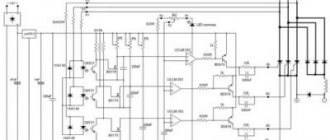
Now let's look at another scheme, only universal, but also not particularly complicated.
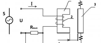
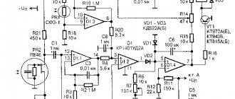
Circuit for testing thyristors and triacs
Designations:
- Resistors: R1, R2 and R4 – 470 Ohm; R3 and R5 – 1 kOhm.
- Capacities: C1 and C2 – 100 µF x 10 V.
- Diodes: VD1, VD2, VD5 and VD6 – 2N4148; VD2 and VD3 – AL307.
A 9V battery, Krona type, is used as a power source.
Testing of SCRs is carried out as follows:
- Switch S3 is moved to the position as shown in the diagram (see Fig. 6).
- Briefly press button S2, the element under test will open, which will be signaled by the VD LED
- We change the polarity by setting switch S3 to the middle position (the power is turned off and the LED goes out), then to the bottom.
- Briefly press S2, the LEDs should not light up.
If the result corresponds to the above, then everything is in order with the tested element.
Now let's look at how to check symmetrical thyristors using the assembled circuit:
- We carry out steps 1-4.
- Press the S1 button - the VD LED lights up
That is, when you press the S1 or S2 buttons, the VD1 or VD4 LEDs will light up, depending on the set polarity (the position of the S3 switch).
Triac? Hear it for the first time
A triac is one of the subtypes of thyristors, which usually consists of many thyristors. In another way it is also called a symmetrical triac.
What does this triac consist of?
Physicists very often present a triac in the form of a five-layer semiconductor. There are also images in the form of 2 thyristors. At the same time, the control is very different from how the switched-on triode thyristors are controlled, which is why they were separated into a separate group. Let's now find out how the controls work.
Triac control
The fact is that an ordinary thyristor has both a cathode and an anode, and each of them performs a strictly defined function, but with a triac everything is a little different. Let's imagine that we have both a cathode and an anode, but when the triac is connected and working, the cathode becomes the anode, and the anode becomes the cathode. This is such a wonderful transformation. That is why we cannot say that they are present here explicitly and will simply call them outputs (electrodes). In order not to be mistaken, let's call the outputs of the triac the conventional cathode and anode. A little more theory.
For a triac, the control works as follows: at the input, the polarity can be either negative - this is the first option. The second option is when it matches the polarity at the anode, which is less common. Then everything is simple - we set the required current strength and it is enough to unlock the triac. Please note that the control electrode is specially made for current, which is what we use for this purpose.
Voila! The main difficulty for us here is to choose the ideal current, that’s all!
Triac circuit
Now that we already know quite a lot about the structure of triacs and how they are usually controlled, it's time to see how they look on the circuits and what is interesting here. Take a look at this diagram for example:
Here we should immediately note what the symbols are so that we can further understand all the schemes without any problems. Triacs usually have 3 electrodes, one of which is the gate. It is denoted by the English letter G. Which is a lot more understanding, right? Great! Now let's look at the circuit of a slightly different triac. Notice the differences? Yes, because here the triac is made up of as many as 2 thyristors!
Yeah, why then is it a triac? Why couldn’t it be possible to put a conventional equivalent thyristor circuit here? But the whole point is that such a scheme is controlled somewhat differently.
Triac regulator
Now it's time for us to discuss how a triac regulates voltage. This is actually very interesting. Look. As soon as the triac starts working, a voltage is immediately applied to one of its electrons, which is always variable. Next, a negative current is supplied to the control electrode, which will control the process. As soon as the switching threshold is overcome (it is always known in advance, this is the convenience), the triac will open and the current will begin to pass through it. Note that the triac will stop working the moment the current changes polarity (in other words, it will close). Then everything goes cycle after cycle and repeats itself.
Yeah, that seems clear. What affects the opening and closing speed of a triac? What affects the output force? Everything here is again very simple. As the input voltage increases, the output pulse also increases. Accordingly, if the input voltage is low, then the output pulse will be short. Let's take an example of an ordinary light bulb with a triac. The more voltage we apply, the brighter the light bulb. Great, isn't it?
Triac operating modes
A triac can operate both under the influence of negative current and under the influence of positive current. In total, there are four main operating modes: everything depends on the polarity and input voltage.
What are the main advantages of a triac
Let's look at a triac as a relay. In this role he has many significant advantages:
- cheap. Yes, that's also a plus. So what? When you need a lot at once, it will be very good if you need to spend less
- lasts a very long time (of course, compared to other devices in this class)
- reliability due to lack of contacts
But it also has disadvantages
Of course, ideal devices have not yet been invented, so we have no right to hide them here either:
- severe sensitivity to high temperatures
- works only at low frequencies (it takes too long to open and close)
- Sometimes there are sudden activations due to natural external electromagnetic influence