As is known, household electrical networks carry a voltage of 220 or 380 V. Usually this is exactly what this or that equipment requires. However, some electrical appliances cannot work with such high performance, and safety is not the last priority here. In this case, a special device is used - a step-down transformer 220 to 12 volts, which allows you to provide the required voltage. Today we’ll talk about the types of such devices, their operating principle and purpose. It is worth considering the possibility of independently assembling a step-down transformer circuit at home.
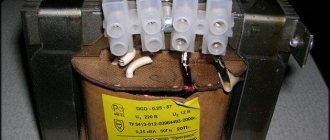
The step-down transformer can be designed for any value. 220/6.5V is rarely used
Step-down transformer 220 to 12 volts: areas of application
Today, many appliances used in everyday life require reduced voltage. These are modern televisions, personal computers and laptops, and various gadgets. However, these devices either come complete with a transformer, called a power supply, or it is built into the device. But lighting is a separate issue. Halogen or LED lamps (especially those installed in rooms with high humidity) require a separate voltage reduction device. This is due to safety requirements, although efficiency also plays an important role.
Important! When purchasing a transformer for 12 volt LED lamps for the bathroom, you need to pay attention to the IP protection class. The device must be protected from splashes to avoid short circuits and failure. For a living room or bedroom, this requirement is not significant.
Transformer operating principle: general information
All such devices, regardless of type, perform similar work. The transformer is supplied with voltage, which is lowered using coils or certain electronic components to the desired value. Such devices can be step-down (the output voltage is less than the input) or step-up (the output voltage is higher than the input). For domestic needs, step-up transformers are irrelevant, because 220 V is quite enough to operate all electrical appliances.
Buck converter made in the USSR - they still work
Let's look at the types of transformers used in everyday life today.
Separation of voltage-reducing devices by type
Transformers are divided according to design features into 2 types:
- Toroidal, or electromagnetic , is an outdated option that has large dimensions and a lower efficiency factor (efficiency). This type is practically no longer used for domestic needs;
- electronic (pulse) devices are compact, lightweight, with a high percentage of efficiency, tending to 100%.
Despite the fact that the former are gradually being replaced by the latter in all areas, it would be a mistake not to consider them.
Toroidal transformer 220 to 12 volts: device, circuit
A fairly simple device consisting of two coils with different numbers of turns mounted on one steel core. The change in output voltage depends on the difference in turns. According to the laws of physics, any conductor through which electric current flows creates an electromagnetic field around itself, which intensifies when the wire is wound into a coil. Thus, the current flowing through the primary coil (to which voltage is applied) creates a strong electromagnetic field, which is transmitted through the steel core to the secondary coil, from which the voltage is removed.
Chinese converters can be quite high quality
Important! Without a steel core, such a device will not work, even if the secondary coil is wound directly onto the primary one. Moreover, such an attempt will lead to the primary coil wire burning out.
Below is a diagram of a simple toroidal transformer.
Electronic device for reducing household voltage
The circuit of the 220 to 12 volt electronic transformer is more complex, however, its operating principle is the same. A small ferrite ring with windings acts as a steel core with a large number of turns. The main work is performed by thyristors (dinistors), various limiting resistors and transistors. A detailed diagram can be found below.
Pulse step-down devices have a number of advantages over electromagnetic ones:
- small dimensions and weight;
- high efficiency;
- minimal heating, which is completely unnoticeable with proper ventilation;
- long service life.
Important! Despite all the advantages of pulse generators, they have one drawback - such a transformer cannot be connected to the network without a load. If turned on in this way, the device quickly burns out.
Classification and types
Step-down transformers are classified according to several parameters:
- by design - electromagnetic and pulsed;
- according to technical characteristics - electrical power, the maximum permissible for connecting the load;
- by type of execution - open or placed in a protective housing;
- by type of use - household and industrial.
The most noticeable difference that determines the possibilities of using and applying 220/12 Volt step-down transformers is their design.
Model of a step-down transformer for domestic and industrial use, placed in a protective housing
Toroidal (electromagnetic) models
A toroidal (electromagnetic) transformer 220 to 12 Volts is a classic version of such devices. The design of electromagnetic models consists of a core made of special types of steel, on which the primary and secondary windings are wound. The transformation of electrical energy occurs due to the electromagnetic force generated in the body of the core.
The advantages of the design are:
- reliability;
- a variety of models with different technical characteristics and types of execution;
- relatively low cost.
The disadvantages include:
- heavy weight;
- sensitivity to voltage surges in the power supply network.
Model of an electromagnetic transformer intended for domestic use
Electronic (pulse) models
Pulse models are assembled from electronic components, which significantly expands the capabilities of step-down transformers of this type.
The advantages of electronic devices are:
- small overall dimensions and light weight;
- resistance to voltage surges in the supply network;
- stability of voltage values at the device output;
- smooth start when turned on and high power factor.
The basis of this type of design is a ferrite core with an electrical winding made on it, as well as transistors, diodes and other electronic components.
Design of an electronic step-down transformer 220/12 Volt
Technical specifications: what you should pay attention to
There are 3 main parameters that you should pay attention to. This:
- input voltage value (220 or 380 V). In the case of household lighting, you should choose a device with an indicator of 220 V;
- output voltage – must correspond to 12 V;
- power. This indicator is calculated from the total load that the lamps will create. For example, if you plan to connect 9 lamps of 15 W, then the power of the transformer should be 150 W.
Expert opinion
Igor Marmazov
ES, EM, EO design engineer (power supply, electrical equipment, interior lighting) ASP North-West LLC
Ask a specialist
“You should not purchase a step-down device with a large power reserve. This will lead not only to unnecessary purchase costs, but also to a shorter service life. A margin of 10-15% is considered optimal.”
Related article: 12V power supply for LED strip. Types of devices, pros and cons of use, connection options, overview of models, recommendations - read the publication.
Electronic transformers. Schemes, photos, reviews
Electronic transformers for halogen lamps (HL) are a topic that continues to be relevant among both experienced and very mediocre radio amateurs. And this is not surprising, because they are very simple, reliable, compact, easy to modify and improve, which significantly expands their scope of application. And due to the massive transition of lighting technology to LED technology, ETs have become obsolete and have fallen greatly in price, which, in my opinion, has become almost their main advantage in amateur radio practice.
There is a lot of different information about ET regarding the advantages and disadvantages, design, principle of operation, modification, modernization, etc. But finding the right circuit, especially high-quality devices, or purchasing a unit with the required configuration can be very problematic. Therefore, in this article I decided to present photos, sketched diagrams with wire data and brief reviews of those devices that came (will fall) into my hands, and in the next article I plan to describe several options for alterations of specific ETs from this topic.
For clarity, I conditionally divide all ET into three groups:
- Cheap ET or “typical China”. As a rule, only a basic circuit of the cheapest elements. They often get very hot, have low efficiency, and with a slight overload or short circuit they burn out. Sometimes you come across “factory China”, characterized by higher quality parts, but still far from perfect. The most common type of ET on the market and in everyday life.
- Good ET . The main difference from cheap ones is the presence of overload protection (SC). They reliably hold the load until the protection is triggered (usually up to 120-150%). The equipment is supplied with additional elements: filters, protections, radiators in any order.
- High-quality electric vehicles that meet high European requirements. Well thought out, equipped to the maximum: good heat dissipation, all types of protection, soft start of halogen lamps, input and internal filters, damper and sometimes snubber circuits.
Now let's move on to the ETs themselves. For convenience, they are sorted by power output in ascending order.
1. ET with power up to 60 W.
1.1. L&B
1.2. Tashibra
The two ETs mentioned above are typical representatives of the cheapest China. The scheme, as you can see, is typical and widespread on the Internet.
1.3. Horoz HL370
Factory China. Holds the rated load well and doesn't get too hot.
1.4. Relco Minifox 60 PFS-RN1362
But here is a representative of a good ET made in Italy, equipped with a modest input filter and protection against overload, overvoltage and overheating. Power transistors are selected with a power reserve, so they do not require radiators.
2. ET with a power of 105 W.
2.1. Horoz HL371
Similar to the above model Horoz HL370 (item 1.3.) factory made in China.
2.2. Feron TRA110-105W
There are two versions in the photo: on the left is the older one (2010 onwards) – factory made in China, on the right is the newer one (2013 onwards), reduced in price to typical China.
2.3. Feron ET105
Similar Feron TRA110-105W (item 2.2.) factory China. The photo of the original board was not saved, so instead I’m posting a photo of the Feron ET150, the board of which is very similar in appearance and similar in element base.
2.4. Brilux BZE-105
Similar Relco Minifox 60 PFS-RN1362 (item 1.4.) is a good ET.
3. ET with a power of 150 W.
3.1. Buko BK452
An electric vehicle reduced in price to a factory price in China, into which an overload protection module (SC) was not soldered. And so, the block is quite good in form and content.
3.2. Horoz HL375 (HL376, HL377)
And here is a representative of high-quality ETs with a very rich set of equipment. What immediately catches your eye is the chic two-stage input filter, powerful paired power switches with a volumetric radiator, protection against overload (short circuit), overheating and double overvoltage protection. This model is also significant in that it is the flagship for the subsequent ones: HL376 (200W) and HL377 (250W). The differences are marked in red on the diagram.
3.3. Vossloh Schwabe EST 150/12.645
Very high quality ET from the world famous German manufacturer. Compact, well-designed, powerful unit with element base from the best European companies.
3.4. Vossloh Schwabe EST 150/12.622
No less high-quality, newer version of the previous model (EST 150/12.645), characterized by greater compactness and some circuit solutions.
3.5. Brilux BZ-150B (Kengo Lighting SET150CS)
One of the highest quality ETs I've come across. A very well thought out block with a very rich element base. It differs from a similar model Kengo Lighting SET150CS only in the communication transformer, which is slightly smaller in size (10x6x4mm) with the number of turns 8+8+1. The uniqueness of these ETs is their two-stage overload protection (SC), the first of which is self-healing, configured for a smooth start of halogen lamps and light overload (up to 30-50%), and the second is blocking, triggered when an overload exceeds 60% and requires a unit reboot (short-term shutdown followed by switching on). Also notable is the rather large power transformer, the overall power of which allows you to squeeze out up to 400-500 W from it.
I personally didn’t come across them, but I saw similar models in the photo in the same case and with the same set of elements for 210W and 250W.
4. ET with a power of 200-210 W.
4.1. Feron TRA110-200W (250W)
Similar Feron TRA110-105W (item 2.2.) factory China. Probably the best unit in its class, designed with a large power reserve, and therefore is the flagship model for the absolutely identical Feron TRA110-250W, made in the same housing.
4.2. Delux ELTR-210W
A maximally cheap, slightly clumsy ET with many unsoldered parts and heat dissipation of power switches to a common radiator through pieces of electrical cardboard, which can be classified as good only because of the presence of overload protection.
4.3. Light kit EK210
According to the electronic filling, similar to the previous Delux ELTR-210W (clause 4.2.), a good ET with power switches in a TO-247 housing and two-stage overload protection (SC), despite which it ended up burnt out, almost completely, along with the protection modules ( why are there no photos? After complete recovery, when connecting a load close to the maximum, it burned out again. Therefore, I can’t say anything sensible about this ET. Possibly a marriage, or perhaps poorly thought out.
4.4. Kanlux SET210-N
Without further ado, a pretty high-quality, well-designed and very compact ET.
ET with a power of 200W can also be found in paragraph 3.2.
5. ET with a power of 250 W or more.
5.1. Lemanso TRA25 250W
Typical China. The same well-known Tashibra or a pitiful semblance of Feron TRA110-200W (section 4.1.). Even despite the powerful paired keys, it hardly maintains the declared characteristics. The board was received crippled, without a case, so there is no photo of it.
5.2. Asia Elex GD-9928 250W
Essentially the TRA110-200W model improved to a good ET (clause 4.1.). Up to half of the housing is filled with a thermally conductive compound, which significantly complicates its disassembly. If you come across one and need to disassemble it, put it in the freezer for several hours, and then quickly break off the frozen compound piece by piece until it warms up and becomes viscous again.
The next most powerful model, Asia Elex GD-9928 300W, has an identical body and circuit.
ET with a power of 250W can also be found in paragraph 3.2. and clause 4.1.
Well, that’s probably all ET for today. In conclusion, I will describe some nuances, features and give a couple of tips.
Many manufacturers, especially cheap electric vehicles, produce these products under different names (brands, types) using the same circuit (case). Therefore, when searching for a circuit, you should pay more attention to its similarity than to the name (type) of the device.
It is almost impossible to determine the quality of an ET based on the body, since, as can be seen in some photos, the model may be understaffed (with missing parts).
The cases of good and high-quality models are usually made of high-quality plastic and can be disassembled quite easily. Cheap ones are often held together with rivets, and sometimes glued together.
If, after disassembling, it is difficult to determine the quality of an electronic device, pay attention to the printed circuit board - cheap ones are usually mounted on getinax, high-quality ones are mounted on PCB, good ones, as a rule, are also mounted on PCB, but there are rare exceptions. The quantity (volume, density) of radio components will tell you a lot. Inductive filters are always absent in cheap ETs.
Also, in cheap ETs, the heat sink of power transistors is either completely absent, or is placed on the housing (metal) through electrical cardboard or PVC film. In high-quality and many good ETs, it is made on a volumetric radiator, which usually fits tightly to the body from the inside, also using it to dissipate heat.
The presence of overload protection (SC) can be determined by the presence of at least one additional low-power transistor and low-voltage electrolytic capacitor on the board.
If you plan to purchase an ET, then note that there are many flagship models that are cheaper in price than their “more powerful” copies. Electronic transformers on AliExpress.
Success in life and creative work to all.
Tags:
- Electronic transformer
- power unit
Transformer for a chandelier: selection criteria
When choosing such equipment, you should pay attention not only to the technical characteristics, but also to the possibility of placement. If you plan to install a stretch or suspended ceiling, no questions will arise. But in the absence of them, everything becomes a little more complicated. You can choose a fairly compact device that fits in a junction box, but it is worth considering that small dimensions also mean less power, which may not be enough if there are a lot of consumers. If the standard transformer in the chandelier fails, then everything is simple - we dismantle it and purchase an identical one. Now let’s look at what to do if you decide to change incandescent lamps to halogen or LED.
Let's consider the option. It is planned to install 8 halogen lamps with a power of 30 W each. We make calculations: 8 × 30 + 10% = 264 W. Paying attention to the range of capacities offered by the manufacturer, you can see that the closest figure to the larger side is a 12 volt 300 watt transformer. This is what you should purchase. Below you can see a diagram of an electronic transformer for 12 V halogen lamps.
An electronic transformer is a network switching power supply, which is designed to power 12 Volt halogen lamps. Read more about this device in the article “Electronic transformer (introduction)”. The device has a fairly simple circuit. A simple push-pull self-oscillator, which is made using a half-bridge circuit, the operating frequency is about 30 kHz, but this indicator strongly depends on the output load. The circuit of such a power supply is very unstable, it does not have any protection against short circuits at the output of the transformer, perhaps precisely because of this, the circuit has not yet found widespread use in amateur radio circles. Although recently there has been a promotion of this topic on various forums. People offer various options for modifying such transformers. Today I will try to combine all these improvements in one article and offer options not only for improvements, but also for strengthening the ET.
We won’t go into the basics of how the circuit works, but let’s get down to business right away. We will try to refine and increase the power of the Chinese Taschibra electric vehicle by 105 watts.
To begin with, I want to explain why I decided to take on the powering and alteration of such transformers. The fact is that recently a neighbor asked me to make him a custom-made charger for a car battery that would be compact and lightweight. I didn’t want to assemble it, but later I came across interesting articles that discussed remaking an electronic transformer. This gave me the idea - why not try it?
Thus, several ETs from 50 to 150 Watts were purchased, but experiments with conversion were not always completed successfully; of all, only the 105 Watt ET survived. The disadvantage of such a block is that its transformer is not ring-shaped, and therefore it is inconvenient to unwind or rewind the turns. But there was no other choice and this particular block had to be remade.
As we know, these units do not turn on without load; this is not always an advantage. I plan to get a reliable device that can be freely used for any purpose without fear that the power supply may burn out or fail during a short circuit.
Improvement No. 1
The essence of the idea is to add short-circuit protection and also eliminate the above-mentioned drawback (activation of a circuit without an output load or with a low-power load).
Looking at the unit itself, we can see the simplest UPS circuit; I would say that the circuit has not been fully developed by the manufacturer. As we know, if you short-circuit the secondary winding of a transformer, the circuit will fail in less than a second. The current in the circuit increases sharply, the switches instantly fail, and sometimes even the basic limiters. Thus, repairing the circuit will cost more than the cost (the price of such an ET is about $2.5).
The feedback transformer consists of three separate windings. Two of these windings power the base switch circuits.
First, remove the communication winding on the OS transformer and install a jumper. This winding is connected in series with the primary winding of the pulse transformer. Then we wind only 2 turns on the power transformer and one turn on the ring (OS transformer). For winding, you can use a wire with a diameter of 0.4-0.8 mm.
Next, you need to select a resistor for the OS, in my case it is 6.2 ohms, but a resistor can be selected with a resistance of 3-12 ohms, the higher the resistance of this resistor, the lower the short-circuit protection current. In my case, the resistor is a wirewound one, which I do not recommend doing. We select the power of this resistor to be 3-5 watts (you can use from 1 to 10 watts).
During a short circuit on the output winding of a pulse transformer, the current in the secondary winding drops (in standard ET circuits, during a short circuit, the current increases, disabling the switches). This leads to a decrease in the current on the OS winding. Thus, generation stops and the keys themselves are locked.
The only drawback of this solution is that in the event of a long-term short circuit at the output, the circuit fails because the switches heat up quite strongly. Do not expose the output winding to a short circuit lasting more than 5-8 seconds.
The circuit will now start without load; in a word, we have a full-fledged UPS with short-circuit protection.
Improvement No. 2
Now we will try to smooth out the mains voltage from the rectifier to some extent. For this we will use chokes and a smoothing capacitor. In my case, a ready-made inductor with two independent windings was used. This inductor was removed from the UPS of the DVD player, although homemade inductors can also be used.
After the bridge, an electrolyte with a capacity of 200 μF should be connected with a voltage of at least 400 Volts. The capacitor capacity is selected based on the power of the power supply 1 μF per 1 watt of power. But as you remember, our power supply is designed for 105 Watts, why is the capacitor used at 200 μF? You will understand this very soon.
Improvement No. 3
Now about the main thing - increasing the power of the electronic transformer and is it real? In fact, there is only one reliable way to power it up without much modification.
For powering up, it is convenient to use an ET with a ring transformer, since it will be necessary to rewind the secondary winding; it is for this reason that we will replace our transformer.
The network winding is stretched across the entire ring and contains 90 turns of wire 0.5-0.65 mm. The winding is wound on two folded ferrite rings, which were removed from an ET with a power of 150 watts. The secondary winding is wound based on needs, in our case it is designed for 12 Volts.
It is planned to increase the power to 200 watts. That is why an electrolyte with a reserve, which was mentioned above, was needed.
We replace the half-bridge capacitors with 0.5 μF; in the standard circuit they have a capacity of 0.22 μF. Bipolar keys MJE13007 are replaced with MJE13009.
The power winding of the transformer contains 8 turns, the winding was done with 5 strands of 0.7 mm wire, so we have a wire in the primary with a total cross-section of 3.5 mm.
Go ahead. Before and after the chokes we place film capacitors with a capacity of 0.22-0.47 μF with a voltage of at least 400 Volts (I used exactly those capacitors that were on the ET board and which had to be replaced to increase the power).
Next, replace the diode rectifier. In standard circuits, conventional rectifier diodes of the 1N4007 series are used. The current of the diodes is 1 Ampere, our circuit consumes a lot of current, so the diodes should be replaced with more powerful ones in order to avoid unpleasant results after the first turn on of the circuit. You can use literally any rectifier diodes with a current of 1.5-2 Amps, a reverse voltage of at least 400 Volts.
All components except the generator board are mounted on a breadboard. The keys were secured to the heat sink through insulating gaskets.
We continue our modification of the electronic transformer, adding a rectifier and filter to the circuit.
The chokes are wound on rings made of powdered iron (removed from a computer power supply unit) and consist of 5-8 turns. It is convenient to wind it using 5 strands of wire with a diameter of 0.4-0.6 mm each.
We select a smoothing capacitor with a voltage of 25-35 Volts; one powerful Schottky diode (diode assemblies from a computer power supply) is used as a rectifier. You can use any fast diodes with a current of 15-20 Amps.
AKA KASYAN
How to connect a step-down transformer 220/12V
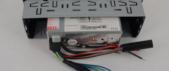
There is a certain procedure for connecting a step-down transformer. First, consumers are connected to the secondary winding, and only then voltage is applied to the primary winding. Installation is carried out according to the diagram contained in the technical documentation. Grounding can be connected in various ways. If the device case is metal, then it can also be grounded. Below are photos of various types of transformers.
Very important! All work related to electrical installation is carried out exclusively with the voltage removed. Remember that electric shock is dangerous to life and health.
If you plan to connect LED lamps, then you need to purchase a transformer with a built-in rectifier or separately include a diode bridge in the circuit, which will provide the constant voltage necessary for stable operation of the light diodes.
How to check a step-down transformer 220 to 12V using a multimeter
If you have a step-down transformer and it is not known whether it is working or what its output voltage is, you can use a multimeter. However, it should be understood that incorrect testing can damage the measuring device. Let's look at the algorithm of actions:
- We visually find the primary and secondary and secondary windings. It's easy to do. The cores of the primary winding are always thinner.
- We set the multimeter switch to set the AC current to the minimum (usually 200 V).
- We apply voltage to the primary winding.
- We take readings from the secondary winding. If there are more than two contacts, we check them alternately. It is possible that, in addition to 12 V, the transformer is capable of delivering 24 and 36 V.
Design and principle of operation
Electronic and electromagnetic models of transformers differ both in their design and in their operating principle, so they should be considered separately:
- Electromagnetic transformer.
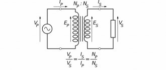
As already written above, the basis of this design is a toroidal core made of electrical steel, on which the primary and secondary windings are wound. There is no electrical contact between the windings; the connection between them is carried out through an electromagnetic field, the action of which is due to the phenomenon of electromagnetic induction. The diagram of a step-down electromagnetic transformer is shown in the figure below, where:
- the primary winding is connected to a 220 Volt network (U1 in the diagram) and electric current “i1” flows in it;
- when voltage is applied to the primary winding, an electromotive force (EMF) is generated in the core;
- The EMF creates a potential difference on the secondary winding (U2 in the diagram) and, as a consequence, the presence of electric current “i2” with a connected load (Zn in the diagram).
Electronic and circuit diagram of a toroidal transformer
The specified voltage value on the secondary winding is created by winding a certain number of turns of wire around the core of the device.
- Electronic transformer.
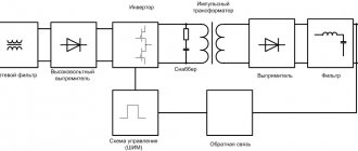
The design of such models provides for the presence of electronic components through which voltage conversion is carried out. In the diagram below, the mains voltage is applied to the input of the device (INPUT), after which it is converted into constant voltage through a diode bridge, at which the electronic components of the device operate.
The control transformer is wound on a ferrite ring (windings I, II and III), and it is its windings that control the operation of the transistors and also provide communication with the output transformer, which supplies the converted voltage to the output of the device (OUTPUT). In addition, the circuit contains capacitors that provide the required shape of the output voltage signal.
Schematic diagram of an electronic transformer 220 to 12 Volts
The above electronic transformer circuit can be used to connect halogen lamps and other light sources operating at 12 Volts.
How to make a 220 to 12V transformer with your own hands
To make your own step-down transformer, you will need the following materials:
- a core that can be taken from an old TV;
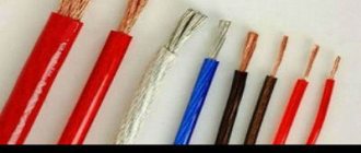
- varnished fabrics;
- thick cardboard;
- boards and wooden blocks;
- steel rod;
- glue and saw.
First, let's look at the option of making a simple machine for winding wire.
| Illustration | Action to be performed |
| This is the simplest device for winding wire onto a reel. The diagram clearly shows how it can be assembled. However, there are more convenient devices that will speed up the process. | |
| Using an ordinary vice, a steel rod and a brace (hand drill), you can assemble a winding device that will save effort and time. | |
| Another device you can’t do without. Often old coils are used to make a transformer. It is this machine, together with one of the previous devices, that will allow you to carefully rewind the wire from one reel to another. |
Now we should consider making a cardboard frame onto which the wire will be wound directly.
| Illustration | Action to be performed |
| The dimensions of the frame are measured according to the core (it should fit inside quite tightly). Based on the fact that the core can be either made of ordinary plates or with a perforation, we invite the reader to familiarize themselves with both options. | |
| We make a pattern according to the dimensions, which is glued together. For fixation, you can use any glue, but it is better to give preference to waterproof one. The best option would be epoxy. | |
| And here you can see the size ratio of the prefabricated frame, which is more difficult to manufacture, but more reliable and does not require gluing. Remember that failure to comply with the parameters may lead to unstable operation of the transformer. |
When everything you need is ready, you can start winding. This work also has its own nuances that should be taken into account.
| Illustration | Action to be performed |
| The wire should be unwound from the “donor” coil from the top, and wound, on the contrary, from the bottom up. The distance between the coils should not be less than a meter. The wire is held with the right hand, and rotation is done with the left. | |
| Terminals for various voltage values are sealed using insulating gaskets. They can be made from wound wire or soldered a flexible lead to it, which is more convenient. The place of adhesion must be isolated. The lead is passed through a hole in the cheek and fixed. In order not to get confused later (if there are several conclusions), it is better to label it immediately. | |
| The fixing insulating pads are glued, however, even in this case, additional fixation is necessary. | |
| The figure shows how the fixing insulating pads are clamped with a wound wire. It is important to do everything according to the instructions - only in this case can you hope for a positive result. Remember that the turns of the wire must fit tightly to each other - this will ensure a stable magnetic field of the coil. |
Calculation of the number of turns of the primary and secondary windings
The main work in the manufacture of a transformer can be called calculating the number of turns of the primary and secondary windings. On average, for a converter of 90−150 W, the number of turns per 1 V equal to 50 Hz / 10 = 5 is taken into account. The total number is calculated using the formulas:
- W1 = 220 × 5 = 1100;
- W2 = 12 × 5 = 60.
We get the required number of turns of the primary winding - 1100, and the secondary - 60.
Making a step-down transformer from 220 to 12 Volts with your own hands
Currently, you can find on sale any step-down transformer that meets all the requirements for this type of technical device. However, for people who have a creative streak and want to make everything with their own hands, it is quite possible to assemble a step-down transformer with their own hands. All work on the independent production of such a product can be divided into several stages: preparatory, execution of work and testing of functionality.
The choice of design and assembled circuit depends on the skills and capabilities of the performer
Preparatory stage
At this stage you should:
- decide on the type of device to be assembled - electromagnetic or electronic;
- determine the technical parameters necessary for further use - power and installation location, permissible overall dimensions and weight;
- calculate the parameters of the primary and secondary windings, in the case of manufacturing an electromagnetic model;
- purchase the necessary materials and components.
When making an electronic device, soldering iron skills and basic knowledge in the field of electronics are required. In this case, the device circuit is initially selected, and, accordingly, electronic components (transistors, capacitors, etc.) are prepared for it. In the case of manufacturing an electromagnetic model, you will first need to calculate the windings of the assembled device, and then perform all other operations.
Design of the simplest electromagnetic transformer
To determine the number of turns N1 in the primary winding, you must use the formula:
N1 = (40 – 60) / S , where
- S – cross-section of the magnetic circuit (core) of the transformer, measured in cm2;
- 40–60 is an indicator (constant) that determines the type and quality of the core.
The cross-section of the core is determined based on the geometric dimensions of the blanks used: window, width and thickness of the core jaws. The cross-section of the wire in the primary winding must correspond to the current that will flow in it during operation, which is determined by the size of the connected load, in numerical terms this is defined as:
I1 = P/U , where
- I1 – current flowing in the primary winding;
- P – power of the connected load;
- U – voltage on the primary winding.
Accordingly, knowing the amount of current flowing through the wires, you can select their permissible cross-section, in accordance with the requirements regulated by the Electrical Installation Rules (PUE). The wire cross-section for the secondary winding is determined in a similar way.
When manufactured independently, the core can be selected in various shapes and designs
The number of turns in each winding is determined by the formula:
W = U × (V / 10) where
- W – number of turns in the winding;
- U – voltage in the transformer winding;
- V – frequency of electric current – 50 Hz.
Having decided on the number of turns, and therefore the dimensions of the core, as well as the required length and cross-section of the wire in both windings, you can prepare the necessary materials to complete the work:
- wire for both windings;
- core - you can purchase a new one or use it from used equipment (TV, radio, etc.);
- insulating materials (tape, paper and others).
In addition, it is possible to make a winding machine that facilitates the production of windings, in the case of the option when the windings are made in the form of coils placed on the core.
Execution of work
When all preparatory activities have been completed, you can begin manufacturing and assembling the transformer, in this case the work is performed as follows:
| Illustration | Description of action |
| The coil frames are made from electrical cardboard or other material. | |
| Using a winding machine or manually, wire is wound onto coils; the number of turns on each coil must correspond to the values determined by calculation for each winding. | |
| The coils are placed on the prepared core, their ends are fixed and marked accordingly. |
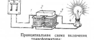
Functionality check
When the transformer is assembled and all its components are securely fastened and insulated, it is necessary to check its functionality. To do this, a voltage of 220 Volts is supplied to the primary winding, and a load designed to operate at a voltage of 12 Volts is connected to the secondary winding.
If the test is successful, the assembled product is placed in the prepared housing or installed in the location intended for placement.
Prices for transformers 220 to 12 volts
Let's consider at what price you can buy 220 to 12 volt transformers on the Russian market. Prices are as of April 2018.
| Photo | Brand | Power, W | Average cost (as of April 2022), rub. |
| Feron | 60 | 150 | |
| TRA54 | 200 | 500 | |
| TRA110 | 250 | 375 | |
| Pondtech | 75 | 4200 | |
| Relco | 250 | 4100 |
As you can see, the price range is quite wide. It depends on the brand and quality of components, which means you shouldn’t think that a step-down transformer for 150 rubles. will work for a long time.
Let's sum it up
Before purchasing a step-down transformer for your home, it is important to calculate all the parameters. You should not treat this carelessly, because the durability of the converter depends on the correctness of the calculations. If you decide to make such a device yourself, then you need to be even more careful about the calculations. Unless, of course, the home master expects to use a ready-made converter.
We hope that our dear reader has found the information he needs in today’s article. If you have any questions on the topic, ask them in the discussions below. The editors of Seti.guru will be happy to answer them. And perhaps someone has experience in making step-down transformers (whether successful or not). In this case, please share it with novice home craftsmen. And finally, we suggest you watch a short but very informative video on today’s topic.