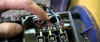
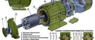
At the moment, on the car radio market, you can see a huge range of devices for passenger cars; the situation is completely different with trucks. The supply voltage in cars comes from a 12-volt battery, while in trucks the supply voltage is 24 volts.
Car radio 12 volt
Trucks, as a rule, are equipped from the factory with standard 24-volt car radios, but to replace such a radio with a newer one or simply as a result of a breakdown, a small problem arises. The share of 24 Volt radios is very small compared to their 12 Volt “colleagues”; this is not surprising if we compare the number of trucks and cars. In this article, we will look at the most popular models of car radios with a voltage of 24 Volts, their features and options for connecting a 12 Volt to 24 Volt radio.
Three power supplies for the car from 24 to 12 volts.
The on-board voltage of most trucks is 24 V;
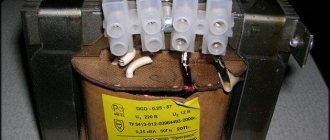
This is also the rated voltage of the batteries. And most of the manufactured assistant devices intended for use in cars (electric coffee makers, heaters, TVs, radios, CD players, etc.) are designed for a supply voltage of 12 V ± 20%. To power them, 24–12 V converters are used. It happens that branded voltage converters cannot withstand overload (especially if several devices are used simultaneously as consumers).
Replacing a stabilizer (as well as repairs by a qualified professional) costs significant money. And when I had to repair 24-12 V converter blocks, eliminating the same fault, I installed a small circuit in the “proprietary” case, which has been working flawlessly ever since.
Truck repair - computer diagnostics and troubleshooting of electrical equipment, chassis, engine, chassis.
In Fig. Figure 2.8 shows the electrical circuit of a simple 24–12 V DC voltage converter-stabilizer on the KR1180EN12V microcircuit.
Rice. 2.8. Electrical circuit of a voltage converter on a KR1180EN12V microcircuit
The KR1180EN12V microcircuit is a voltage stabilizer with a fixed positive output voltage of 12 V, has protection against short circuits and thermal overheating. Chip D1 produces a fixed output voltage of +12 V with a maximum permissible load current of 2.2 A.
The peculiarity of the KR1180EN12V microcircuit in comparison with similar analogs (in terms of electrical characteristics) is as follows: the maximum power dissipation Ptot (max) is 15 W, and the maximum permissible input voltage is 35 V. Implemented in a package of the KT-28-2 type, the stabilizer microcircuit also has a large reserve by maximum temperature stability - transition temperature Tper
Rice. 2.9. Electrical circuit of the voltage stabilizer in the on-board 12 V network
The chip also needs to be installed on the radiator. KREN8B, in accordance with the electrical characteristics, provides a maximum load current of 1.5 A and has protection against short circuits at the output. However, in this circuit it works in conjunction with a current amplifier on the KT819BM, so the maximum load current is significantly higher than what the microcircuit alone could provide.
In practice, car owners are well aware of how important it is to ensure that the CD player operates without interference; and the device, the diagram of which is shown in Fig., helps with this. 2.9. Interference affecting people in a car can be divided into two categories:
• power supply interference (LF interference);
• HF (high frequency) interference.
RF interference can be eliminated by using a high-quality antenna and/or using a tuner with a selective high-frequency path. In my practice, power supply interference is eliminated by using low-pass filters and the one recommended in Fig. 2.9 stabilizer, specially designed and practically tested for these purposes.
The results of using this electronic device are such that the stabilizer shown in the electrical diagram delays low-frequency interference created by the operation of the car engine in all its modes, as well as by additional electrical equipment. The standard heater fan and (or) an additional fan for cooling the interior, powered from the cigarette lighter connector, before using this circuit, created noticeable low-frequency interference (background), perceived through the speaker system of the CD player. The device localizes interference from the cabin air conditioner and (or) car radiator cooling fan.
About details and installation Capacitors C1–C4, connected in parallel to the diodes of the rectifier bridge, and capacitor C3 at the output of the device cut off “background” interference when powerful consumers operate in the on-board network. Capacitors C2, C4 filter the power, eliminating surges and short-term voltage drops.
Transistor VT1 is controlled by a stabilizer chip KR142EN8B (amplifies the current) and provides a stabilized output voltage of 12 V ± 5%. Transistor VT1 must be installed on the heat sink and replaced with KT815, K817A–K817B. In this option, the output current will be slightly reduced. Transistor VT1, “boosted” by a stabilizer chip, is capable of delivering a current of several amperes (in practice, the device was tested with a load with a current of 3.3 A).
This should be taken into account when choosing stabilizer operating modes. The device has been tested as a power adapter for CD players from Panasonic and Kenwood. As a basic circuit, the adapter can be used in a wide range of other tasks facing a radio amateur. The device can be used to recharge batteries of portable electronic and household appliances, including mobile phones.
The distinctive features of the proposed circuit (Fig. 2.9) are also that when an “increased” constant supply voltage is supplied to the input, the D1 microcircuit is capable of producing a stabilized, regulated output voltage of 12 V. In Fig. Figure 2.10 shows a variant of the electrical circuit using the KR142EN12A stabilizer microcircuit, which allows the output voltage to be adjusted within a wide range.
This circuit was tested in an adjustable stabilizer, the power source of which is the same battery with a nominal voltage of 24 V, taken from a Volvo FL6 truck. Illustrated in Fig. 2.10 turning on the KR142EN12A microcircuit allows you to obtain a stabilized voltage at the output in the range of 1.2–21 V. The microcircuit must be installed on a heat sink. The device is protected against short circuit at the output.
It can be used not only in a car, but also in other amateur radio designs. Thus, when a constant voltage is supplied to the input within the range of 36...40 V, the device is capable of producing a stabilized output voltage from 1.2 V to 37 V, respectively, with a load current of up to 1 A. When it is necessary to set a fixed output voltage on the stabilizer, for example 12 V, by adjusting a variable resistor with a resistance of 5.6 kOhm, the required output voltage is achieved, then the resistance of the resistor (by removing one terminal) is measured with an ohmmeter, and the variable resistor is replaced with a constant one.
After reading this section, any driver who has even a little practical knowledge of electronics (but knows how to use a soldering iron for its intended purpose) can independently assemble the converter circuit and remove the problem of reliability and repair of this electronic unit.
Author; A. KASHKAROV, St. Petersburg.
Source
Device and design
A simple 12-volt power supply without a transformer can be made from several radio elements. It consists of a VD1-4 diode bridge and 3 similar transistor stabilizers connected in series.
C1, connected to a 220 V network, extinguishes most of the voltage. It is rectified by the diode bridge VD1-4. Chain D1, C2 is a parametric stabilizer, from the output of which the constant voltage supplying the load is removed.
A more advanced device contains a resistance R1 at the input to suppress the inrush current and an RC circuit - a damping capacitance C1 and a high-value resistor r2 connected in parallel to discharge it. The middle part of the diagram is the same. An additional non-polar capacitor C3 is installed at the output.
Further improvement involves installing a VR1 stabilizer on transistors or a microcircuit at the power supply output.
These blocks are dangerous, since their parts are energized by 220 V. In the absence of load (if the stabilizer is damaged), the output potential will be equal to the network potential.
Expert opinion
It-Technology, Electrical power and electronics specialist
Ask questions to the “Specialist for modernization of energy generation systems”
Transformerless 12 Volt power supply with your own hands at home Unfortunately, there are many models of dubious quality; according to reviews from owners, transformers have a short service life and require frequent replacement. Ask, I'm in touch!
Voltage converters 24-12
I know that sometimes in a car with an on-board 24V network, it is necessary to turn on 12V equipment, many people ask questions. This article will try to popularly answer the most common of them.
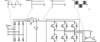
“Converter” (or Adapter), (or Converter) is a 24 to 12 volt device that accordingly converts the voltage and ensures its stabilization. There are 2 types: “hot” and “cold”. Hot - linear type converters. Let's say you converted 24 volts to 12 and connected a 10A load (powerful radio station). Those. The converter, as it were, takes the input voltage, cuts off 12 volts from it, and makes heat from the remaining 12 volts. To do this, a powerful radiator is needed on its body. The thermal power released in this case is calculated as cut-off voltage * flowing current = watts. You can take an interest in converters in the corresponding section: https://ipbelova.clan.su/load/5 or from the photo https://ipbelova.clan.su/photo/4 Cold ones are essentially generators that spin up from the input voltage and generate special pulse sequences that are converted into output voltage at the device output. If the voltage is ready, there are no pulses, and therefore there is no excess heat. However, they make quite a lot of noise, which can harm radio stations and tape recorders.
Schematic diagram of the generator module
The PWM module generates pulse width modulation (PWM) oscillations at the outputs S1, S2, this signal is proportional to the real intention in the VSF points of the output circuit (source output voltage) and the module record, these points are on the positive feedback of the module, a certain value is achieved by changing its value by resistor P1 in the PWM module. The printed circuit board is in the archive.
The temperature control module is responsible for maintaining the temperature of the MOSFET amplifier. You can not use it at all, but supply power to the cooler directly.
The master oscillator signal amplifier is assembled on a driver for MOSFET - IR2111. PWM oscillations after mixing on diodes have a resulting signal - a square wave with a fixed frequency of 70kHz, pulse width from 0% to 98%. Next, the output of the square wave signal is amplified by cascades at T1, T2, T3, and filtered by inductor L2. After L2, it is rectified by a group of diodes D10 and D11 - these are high-performance Schottky type, suitable for use in switching power supplies. And finally, the 12V voltage is filtered and stabilized by two electrolytic capacitors C10, C11. As a result, the supply voltage is very stable.
Originally posted 2019-04-08 02:57:11. Republished by Blog Post Promoter
How to connect 24 volts
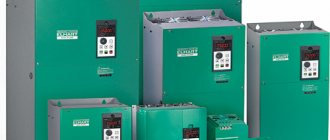
The main function of the inverter is to convert the DC current from the battery into alternating current suitable for connecting household electrical appliances. The output voltage is 220 volts, with a frequency of 50 Hz. For ease of use, each inverter device is equipped with a standard socket. Passenger cars typically use 12 to 220 V inverters. The more powerful 24 to 220 V inverter is used in trucks and buses, and as the main component of an off-grid electrical system.
Where are 24 volt networks used?
On-board networks of buses and trucks operate with a voltage of 24 volts, which makes it possible to eliminate high currents. As a rule, the current source consists of two 12-volt batteries connected to each other in a series circuit. The result of this combination is a battery capable of delivering 24 V. The battery capacities do not add up. This indicator is determined by the weakest battery in this pair.
A series connection eliminates the transfer of current from one battery to another, from a more powerful one to a weaker one. If the less capacious battery is discharged first, then the flow of electric current in the circuit completely stops.
When using such a system, one should take into account the impossibility of proportionally dividing the load current between the batteries. If a household appliance with a power of 500 watts consumes 20 A, then for a powerful battery this will be a very insignificant current, and for a low-power device included in a pair, this load may be unbearable. In this regard, when using a serial connection, both batteries must be identical in all respects. The generator voltage in a truck is usually slightly higher than the voltage in the on-board network and is 28-29 V. Thus, normal conditions are provided for charging batteries connected to a common system.
Working diagrams
All described devices are made using common radioelements. Below are diagrams indicating all the parts.
In a power supply with transistor stabilizers, the KT940A can be replaced with a high-voltage one that can withstand more than 250 V, and the KT815G with another one with a minimum voltage of 80 V. With the specified details, the device can output up to 300 mA. To increase the current, transistors must be installed on radiators. If you install D814D instead of the KS512A zener diode, the output current of the device will decrease to 200 mA.
A traditional transformerless 12V unit with an RC circuit only produces 20-40mA. If you install a powerful D815Zh zener diode after the bridge, which limits the voltage to 16-19 V, and add a transistor stabilizer to the circuit, the output current will increase to 120 mA. To increase it to 180 mA, it is necessary to solder another similar one in parallel with capacitors C1, C2.
The block on the 78L08 chip (Russian designation KR142B) is more stable. With the specified details, it outputs up to 200 mA.
Useful tips Connection diagrams Principles of operation of devices Main concepts Meters from Energomer Precautions Incandescent lamps Video instructions for the master Testing with a multimeter
Operating principle of inverter devices
In order to get the maximum effect from an inverter, you need to know the principle of their operation. The 24 - 220 inverter itself is a device that converts direct current into alternating current. In this case, the voltage value can be changed upward or it remains at the same level.
Most often, a periodic voltage is generated, the output shape of which is obtained in the form of a sinusoid. Theoretically, it is possible to obtain any current - from zero to maximum value, due to adjustments in the control circuit. The incoming current remains unchanged in all cases. The power sources for inverters are batteries delivering 12 or 24 volts.
All inverter devices can be divided into two groups. The first category includes more expensive devices with a clearly defined sinusoidal output voltage. The second group includes cheap models in which the output voltage, instead of a sine wave, takes a more simplified form, for example, a trapezoidal sine.
In its simplest version, a 24V-220V inverter functions as follows. The basis of the design is a transformer, the primary winding of which is connected to two thyristors that open in turn. Such opening alternately turns on the right or left windings, acting in a coordinated and opposite direction. Consequently, a current with a positive or negative value will alternately appear in the secondary winding. In both windings, currents increase or decrease, as well as a change in their direction, depending on the activity of one of the primary windings.
In this simplified version, the output is not a smooth one, but a stepped modified sinusoid, which does not have a significant effect on the operation of the devices. The essence of the inverter’s operation lies not in the conversion circuit itself, but in creating interaction between all processes occurring in the system.
These processes go through three stages:
- It all starts with reducing forward current to zero.
- After which the applied forward voltage is delayed until the thyristor's blocking ability is restored.
- At the final stage, the current in the second thyristor begins to increase.
All events of this scheme can occur simultaneously or sequentially, the most important thing is that there are no failures at any of the stages.
All inverters can operate in several modes:
- Continuous operation in accordance with the rated power of a particular device.
- Working with overload. This period is no more than half an hour, during which the device is capable of delivering power 1.5 times higher than the nominal value.
- Starting mode in which increased power is delivered instantly. This period of time is measured in milliseconds. It is quite enough to start an electric motor or any capacitive load.
Where is it used?
Inverters are most often used in emergency or backup power supply systems. With their help, AC power supplies are created, designed to connect devices and equipment operating from 220 volts. These include kitchen appliances, televisions, and various power tools.
In the event of a power outage, a 24V-220V inverter is capable of providing electricity to a cottage or country house for several hours. If necessary, the converter can be powered by a car battery. In this case, specialists involved in construction and repair can drive up to any point and connect the power tool in the absence of the main network voltage. Mobile inverters have proven themselves very well during travel, as well as hunting and fishing.
A backup power supply system using inverters, used in private homes, ensures complete independence from centralized networks. During blackout periods, power is supplied from batteries, the energy of which is converted using an inverter. When the central network starts working again, the inverter automatically charges the batteries at this time.
When comparing voltage converters with generator sets, it becomes clear that inverter systems have significant advantages. First of all, it is silent operation, there is no need to purchase fuels and lubricants, consumables and spare parts. There are no moving parts, so the converters are considered more reliable and require virtually no periodic maintenance.
How to connect the “Exit” sign to S2000-ASPT.
Surprisingly, the manufacturer did not provide for connecting the “Exit” sign. Perhaps because such a task is rare.
The connection diagram of the device shows that there are no unnecessary controlled outputs (Indicator “The output must be correctly connected to the controlled output”).
The “Leave” and “Don’t Enter” boards have different operating logic. “Go away” is turned on at the moment the delay time countdown starts. “Do not enter” is activated when the extinguishing agent has already been released. And, unlike the MPT-1 Rubezh fire extinguishing control device, the S2000-ASPT device has a rigid binding of output assignments.
You can, of course, connect the “Output” display to the “Power supply for external devices” terminals. But this will be wrong, since there is no monitoring of the state of the warning device circuit.
Is circuit monitoring necessary for the “Exit” sign?
The question is debatable.
When considering options for connecting Exit light signs, we found out that control is most likely needed.
Then the “Output” signs cannot simply be taken and connected to the “ power supply for external devices ” terminals.
It is worth remembering that the “Exit” board with a 24V power supply is a special position and the first “Exit” board picked up will be 12V. Therefore, do not forget about the 600 Ohm resistor.
General characteristics of inverters 24-220
The inverter models produced have a variety of parameters and technical characteristics. This makes it possible to choose the most optimal option for specific operating conditions. However, the general functionality of the devices is almost the same, so as an example we can take a 24V - 220V voltage converter with a power of 200 watts.
This device is designed to receive alternating voltage from the current of a 24V battery. The output produces a stable voltage of 220V, with a frequency of 50 Hz, suitable for operating standard household appliances. All inverters of this type are equipped with their own built-in protection against short circuits, overheating and overloads.
The 24V-220V inverter in question is best suited for use with a car battery. It allows you to most effectively solve priority everyday problems during travel and outings. In addition to the standard socket, the case has a USB connector to which mobile devices can be connected.
The converter operates not only from the battery, but also from the cigarette lighter. It also interacts well with a mobile power station using solar panels.
The main technical characteristics are the following: input voltage - 20-30 volts, output - 220-240 V. Constant output power - 200 W, peak power - 400 W. The green LED indicates normal operating mode, the red light turns on when the protection is triggered. The efficiency is 90%.
At the moment, on the car radio market, you can see a huge range of devices for passenger cars; the situation is completely different with trucks. The supply voltage in cars comes from a 12-volt battery, while in trucks the supply voltage is 24 volts.
Car radio 12 volt
Trucks, as a rule, are equipped from the factory with standard 24-volt car radios, but to replace such a radio with a newer one or simply as a result of a breakdown, a small problem arises. The share of 24 Volt radios is very small compared to their 12 Volt “colleagues”; this is not surprising if we compare the number of trucks and cars. In this article, we will look at the most popular models of car radios with a voltage of 24 Volts, their features and options for connecting a 12 Volt to 24 Volt radio.
Car radios for trucks
The problem is that in trucks the standard places provided for installing car radios have a 24-volt output. And most of the car radios produced in the world have a 12 volt input.
- 24V receivers are quite difficult to find on sale. Therefore, before you connect the car radio and do it yourself, you will need instructions that will help you get out of this situation correctly.
- So, you are in a store that sells car radios - you can connect any receiver you like to your KAMAZ, even a 12-volt one. There are two ways to do this.
- The first of them involves the use of one of the two batteries available in the truck. But this option can only be considered temporary.
- If you do not want to have difficulties in the form of a quickly running out battery, or even a broken car radio, it is better to immediately connect it properly. You need to use a special adapter for this.
- This device is also called a current converter. Any store that sells auto devices sells a lot of adapters from different manufacturers.
The cost of converters can vary significantly (from one to three thousand rubles), but their essence does not change.
For installation you will need a number of types of screwdrivers, a tester, electrical tape, and, of course, an electrical diagram for connecting the car radio. The circuit is usually included with the receiver, but if not, a video will help you.
Connection
The first thing you need to do is pay attention to what type of panel mount is provided for the car radio. Most receivers are universal; their mountings and dimensions must comply with ISO standards.
ISO adapter
- Consider yourself lucky if all the connectors in the body and on the radio are similar. Then connecting it is a matter of minutes. In any case, if the wires from ground, battery, antenna and speaker system were previously laid.
- All that remains is to bypass the ignition switch, install a pulse voltage converter, connect the connectors and listen to music . If the connectors do not fit, you will need to purchase the appropriate adapter.
- It’s better to take care of this before going to the store. Take a photo of the connector in the cockpit and show it to the consultant.
Connecting a 12 volt radio to 24 volt
As mentioned above, it is not always possible to find a 24 Volt radio, or you just want to put a familiar head unit in a truck instead of a standard radio. In this case, the question naturally arises: how to connect a 12 Volt radio to 24? There are several “legends” of connection among users; we will consider them only for informational purposes, so that you know what not to do.
The first option for this connection: if the car has 2 12 V batteries, power is supplied to the radio from the terminal of one of them. This carries the risk of burning the device in case of any problems, and the battery will be constantly discharged and they must be periodically swapped.
Car player Rolsen RCR-102B24
The second connection option, which is recommended by some “smart guys” who heard somewhere from someone something about electrical engineering and resistance, but did not delve into the essence of the issue themselves, is connecting in series with the radio, 12 V loads, to ensure the rated voltage for the device. Such a scheme is not workable in most cases, since it is necessary to match two loads in terms of reactance, and this is very problematic in practical terms. In case of incorrect connection (different reactance), there is a high risk of damaging the radio.
The correct and fairly simple way to connect a radio to 24 Volts is to use a converter specially designed for this purpose, which can be found in a specialized auto shop for truck drivers. For these purposes, many drivers noted the Astron N2412-24 converter as the best option in terms of price and quality. Of course, there are more expensive and functional devices, it all depends on the financial capabilities of the future owner.
Car radios for trucks
The problem is that in trucks, the standard places provided for installing car radios have a 24-volt output. And most car radios produced in the world have a 12 volt input. So:
- 24V receivers are quite difficult to find on sale. Therefore, before you connect the car radio and do it yourself, you will need instructions that will help you get out of this situation correctly.
- So, you are in a store that sells car radios - you can connect any receiver you like to your KAMAZ, even a 12-volt one. There are two ways to do this.
- The first of them involves using one of the two batteries available in the truck. But this option can only be considered temporary.
- If you don’t want to have problems in the form of a quickly draining battery, or even a broken car radio, it’s better to immediately connect it properly. You need to use a special adapter for this.
- This device is also called a current converter. Any store that sells car accessories sells a lot of adapters from various manufacturers. The price of converters can vary significantly (from one to three thousand rubles), but their essence does not change.
- For installation you will need several types of screwdrivers, a tester, electrical tape, and, of course, an electrical diagram for connecting the car radio. The circuit is usually included with the receiver, but if not, a video will help you.
24 Volt models
ROLSEN RCR-102B24
The device is manufactured by a Chinese company, has a supply voltage of 24 Volts and a standard radio size of 1 DIN. Information is displayed on a small monochrome screen, and the radio is controlled using buttons on the panel; there is a USB port on the front side.
The Rolsen 24 Volt radio has a maximum output power of 4X45 W, supports playback of MP3 music files from a flash drive and SD and MMC memory cards. The GU allows you to listen to FM radio stations, with the ability to store up to 18 stations in memory. According to positive user reviews, excellent sound quality is noted for a minimal price, an excellent choice for those who are looking for a radio and nothing more.
URAL (URAL) RU/MP3-219SA (12-24V)
The head unit was developed and manufactured by the Ural company specifically for trucks, the radio supply voltage is 24 Volts. Device size 178X50mm. Information is displayed on a two-color screen; the head unit is controlled using buttons on the front panel of the radio. The Ural 24 Volt radio has a maximum output power of 4x50 W, supports playback of MP3 music files from a flash drive and SD and MMC memory cards, the USB port is located on the front panel of the radio.
Allows you to listen to FM and AM radio stations; it is worth noting the reliable reception on country roads. Users have noted the poor sound quality of so-called Chinese-made devices. When choosing a radio, according to drivers, it is better to take an old Japanese or Korean model than a new Chinese counterfeit; pay attention to this aspect when purchasing.
Supra SFD-1224U
The device is from a Japanese manufacturer, size 1 DIN. One of the features of the radio is the ability to operate on 24 and 12 Volts. The device is connected without any problems using the ISO connector. The radio is equipped with a small monochrome screen on which the necessary information is displayed. Control is performed using the remote control or buttons on the front panel of the device. The output power of the device is 4X50W, there is an equalizer with three presets.
Car radio SUPRA SFD-1224U
Plays music files from flash drives and SD and MMC memory cards, the GU supports MP3 and WMA formats. The front panel has a USB port for connecting removable storage media. Listening to FM and AM radio stations with the ability to store 18 and 12 stations in memory, respectively. User reviews regarding this model are only positive; drivers appreciated the good sound quality at the rather modest price of the device.
Car radio SUPRA SFD-1224U
Why does the problem of connecting 12V devices to 24V arise at all?
The standard supply voltage for fire alarm devices, for example the “Exit” sign, is 12V.
When ordering equipment for a site, all equipment is ordered as 12V by default.
The S2000-ASPT fire extinguishing control device is good because it has a built-in redundant power supply.
But this power supply is 24V, so the control output for the scoreboard, starting circuit and sound notification is also 24V.
The officials who order the equipment do not know these technical issues. Designers writing equipment specifications do too.
That's how it works. There is no time to wait for a 24V board and install the existing 12V boards.
When connecting a 12V display to a 24V output, it will burn out sooner or later.
This is confirmed by practice.
The very first sign that says “Automation is disabled” fails.
The “Powder Do Not Enter” and “Powder Do Not Enter” signs last quite a long time due to their infrequent use.