Regulations
Taking into account the large number of electrical elements, a number of normative documents have been developed for their alphanumeric (hereinafter referred to as BO) and conventional graphic designations (UGO) to eliminate discrepancies. Below is a table showing the main standards.
Table 1. Standards for graphic designation of individual elements in installation and circuit diagrams.
| GOST number | Short description |
| 2.710 81 | This document contains GOST requirements for BO of various types of electrical elements, including electrical appliances. |
| 2.747 68 | Requirements for the dimensions of displaying elements in graphical form. |
| 21.614 88 | Accepted codes for electrical and wiring plans. |
| 2.755 87 | Display of switching devices and contact connections on diagrams |
| 2.756 76 | Standards for sensing parts of electromechanical equipment. |
| 2.709 89 | This standard regulates the standards in accordance with which contact connections and wires are indicated on diagrams. |
| 21.404 85 | Schematic symbols for equipment used in automation systems |
It should be taken into account that the element base changes over time, and accordingly changes are made to regulatory documents, although this process is more inert. Let's give a simple example: RCDs and automatic circuit breakers have been widely used in Russia for more than a decade, but there is still no single standard according to GOST 2.755-87 for these devices, unlike circuit breakers. It is quite possible that this issue will be resolved in the near future. To keep abreast of such innovations, professionals monitor changes in regulatory documents; amateurs do not have to do this; it is enough to know the decoding of the main symbols.
Symbols in electrical diagrams (GOST 7624-55)
In diagrams made in accordance with GOST 7624-55, all designations are given in the “normal” position of the devices, i.e. in the absence of voltage in all circuit circuits and any mechanical effects on the devices.
The graphic designations of the devices include letter designations: ammeter A, voltmeter V, wattmeter W, reactive wattmeter VAR, phase meter φ, frequency meter Hz, active energy meter Wh, reactive energy meter VARh, etc.
The graphic designations of the relay include letter designations of the value to which the relay reacts, or the function performed: current relay or thermal relay RT, voltage relay RN, power relay RM, resistance relay RS, time relay RF, intermediate relay RP, indicating relay RU, gas RG relay, current relay with time delay PTV.
The command devices are designated: KU - control button, KV - limit switch; PV - travel switch; CC - command controller, etc.
Electric motors are encrypted as follows: DG - main engine; DBH - high-speed motor; DO - cooling pump motor; DS - spindle motor; DP - feed motor, etc.
Symbols of wires, individual elements of machines and devices (GOST 7624-55)
| Name* | Designation** | Name | Designation |
| Power circuit wire | Triode (electron tube with three electrodes) | ||
| Control wire | Thermal Relay Heating Element | ||
| Contactor coil | Normally open control button contact | ||
| Voltage relay coil | Normally closed control button contact | ||
| Coil of a current relay or electrical measuring instrument | Active resistance unregulated | ||
| Normally open power contact (n.o.)1 | Active resistance adjustable | ||
| Normally closed power contact (NC)2 | Single-pole switch | ||
| Normally open contact with time delay when closing | Fuse | ||
| Normally open contact with time delay when opening | Rectifier (semiconductor valve) | ||
| Normally closed contact with time delay when opening | Signal lamp | ||
| Normally closed contact with time delay when closing | Three-phase asynchronous electric motor with squirrel-cage rotor | ||
| DC machine | Three-phase asynchronous electric motor with wound rotor | ||
| Measuring device indicating | Measuring recording device | ||
| Counter | Battery made of galvanic or rechargeable cells | ||
| Control key contacts (the state of contacts for different key positions is given in the control key contact diagram) | Electromagnet | ||
| Single-phase transformer | Grounding | ||
| Name* | Designation** | Name | Designation |
Notes
:
1
Normally open contacts are those that open when the relay or contactor is de-energized;
2
Normally closed contacts are those that are closed when there is no current in the relay windings;
Electrical machines (GOST 2.722-68)
| Name | Designation | Name | Designation |
| Stator. Stator winding. General designation | Rotor. General designation and short circuit | ||
| Rotor with winding, commutator and brushes | The car is electric. General designation | ||
| Three-phase asynchronous machine with six output phase ends of the stator winding and with a squirrel-cage rotor | Note . Inside the circle, it is allowed to indicate the following data: a) type of machine (generator - G(G), engine - M(M), tachogenerator - TG(BR), etc.; b) type of current, number of phases or type of winding connection, for example generator three-phase | ||
| Three-phase asynchronous machine with a wound rotor, the winding of which is connected in a star, the stator winding is connected in a triangle | Three-phase non-salient-pole synchronous machine with excitation winding on the rotor; The stator winding is connected in a triangle | ||
| DC machine with series excitation | DC machine with parallel excitation | ||
| Independently excited DC machine | DC machine with mixed excitation | ||
| DC machine with permanent magnet excitation | Single-phase commutator motor of sequential excitation |
Current collectors (GOST 2.726-68)
| Name | Designation | Name | Designation |
| Trolley current collector. General designation | Ring current collector |
Arresters. Fuses (GOST 2.727-68)
| Name | Designation | Name | Designation |
| The fuse is fusible. General designation | Arrester. General designation |
Inductors, reactors, chokes, transformers, autotransformers and magnetic amplifiers (GOST 2.723-68)
| Name | Designation | Name | Designation |
| Winding of transformer, autotransformer, choke and magnetic amplifier | Form I | Single-phase transformer with magnetic core | Form I |
| Form II | Form II | ||
| Single-phase transformer with three-winding magnetic core | Form I | Single-phase autotransformer with magnetic core | Form I |
| Form II | Form II | ||
| Current transformer with one secondary winding | Form I | Choke with ferromagnetic magnetic core | |
| Form II | Reactor |
Electrical measuring instruments (GOST 2.729-68)
| Name | Designation | Name | Designation |
| Watt hour meter | temperature sensor | ||
| Ammeter | Voltmeter |
Light sources (GOST 2.732-68)
| Name | Designation | Name | Designation |
| Incandescent lamp for lighting and signaling Note . It is allowed to blacken the sectors when depicting signal lamps | Gas-discharge lighting and signal lamp. General designation: with four terminals | ||
| High pressure gas discharge lamp with simple electrodes | |||
| Starter (for fluorescent lamps) | Ultra-high pressure gas discharge lamp with simple electrodes |
Chemical current sources (GOST 2.742-68)
| Name | Designation | Name | Designation |
| Galvanic or battery cell | Battery made of galvanic cells or accumulators |
Electric heaters, electrothermal devices and installations (GOST 2.745-68)
| Name | Designation | Name | Designation |
| The installation is electrothermal. General designation | Electrothermal device without heating chamber; electric heater | ||
| Electric resistance furnace. General designation | Induction electric heater. General designation |
Type of current and voltage, types of winding connections, pulse shapes (GOST 2.750-68)
| Name | Designation | Name | Designation |
| DC current | AC three-phase current 50Hz | 3~50Hz | |
| AC current. General designation | Polarity negative | − | |
| Direct and alternating current (designation used for devices suitable for operation on direct and alternating current) | Polarity positive | + |
Electrical communication lines, wires, cables and buses (GOST 2.751-73)
| Name | Designation | Name | Designation |
| Electrical communication line, wire, cable, bus | Grounding | ||
| Housing (machine, apparatus, device) | The graphical intersection of two electrical communication lines that are not electrically connected. The lines must intersect at an angle of 90° | ||
| Broken electrical communication lines Note. In place of the sign x indicate the necessary data on the continuation of the line on the diagram | Electrical communication lines with two branches |
Semiconductor devices (GOST 2.730-73 as amended in 1989)
| Name | Designation | Name | Designation |
| Diode | PNP type transistor | ||
| Light emitting diode | Field effect transistor with channel type N | ||
| Varicap (capacitive diode) | NPN type transistor, collector connected to body | ||
| Photodiode | Unlockable triode thyristor with cathode control | ||
| Zener diode | Triode thyristor, reverse lockable, anode controlled | ||
| Diode thyristor (dinistor) | Photoresistor |
Resistors. Capacitors (GOST 2.728-74)
| Name | Designation | Name | Designation |
| Resistor is constant | Fixed capacitor | ||
| Variable resistor | Polarized electrolytic capacitor | ||
| Direct heated thermistor | Pass-through capacitor Note . The arc denotes the outer lining of the capacitor (housing) |
Sensing part of electromechanical devices (GOST 2.756-76)
| Name | Designation | Name | Designation |
| Electromechanical device coil | Coil of an electromechanical device having a mechanical interlock | ||
| Sensing part of electrothermal relay | Coil of an electromechanical device that operates with acceleration when triggered | ||
| Coil of a polarized electromechanical device Note . It is allowed to use the following designation | Coil of an electromechanical device that accelerates when actuated and released | ||
| Coil of an electromechanical device that operates with a delay when triggered | |||
| Maximum current winding | Coil of an electromechanical device that operates with deceleration when released | ||
| Minimum voltage winding | Coil of an electromechanical device that operates with deceleration when activated and released |
Switching and contact connection devices (GOST 2.755-74)
| Name | Designation | Name | Designation |
| Track switch: single-pole | Contact of an electrothermal relay with a spaced image method | ||
| Push-button switch: with normally open contact | Three-pole switch with automatic return | ||
| with break contact | Contact for switching a high-current circuit (contactor, starter) making |
Switching devices and contact connections (GOST 2.755-87)
| Name | Designation | Name | Designation |
| Switching device contact. General designation: a) closing b) breaking c) switching | Limit switch contact: 1) normally open 2) normally closed | ||
| Manual switch | |||
| Normally closed contact with a delay that operates: 1) when triggered 2) when returned 3) when triggered and returned | Pin connection contact: | ||
| 1) detachable connection: - pin - socket | |||
| Opening contact with a delay that operates: 1) when triggered 2) when returned 3) when triggered and returned | 2) collapsible connection | ||
| 3) permanent connection | |||
| Detachable contact connection | |||
| Thermal relay contact | Single-pole multi-position switch (six-position example) |
Conventions. Switching devices and contact connections (GOST 2.755-87)
This standard applies to diagrams, performed manually or automatically, of products from all industries and construction, and establishes conventional graphic symbols of switching devices and their elements. This standard does not establish conventional graphic symbols on railway signaling, centralization and interlocking diagrams.
Conventional graphic symbols of mechanical connections, drives and devices - according to GOST 2.721-74.
Conventional graphic designations of the receiving parts of electromechanical devices - according to GOST 2.756-76.
The dimensions of individual graphic symbols and the ratio of their elements are given in the Appendix.
1. General rules for constructing contact designations 1.1 Switching devices on the diagrams must be depicted in the position taken as the initial one, in which the starting contact system is de-energized. 1.2 Contacts of switching devices consist of moving and fixed contact parts. 1.3 To depict the main (basic) functional features of switching devices, conventional graphic designations of contacts are used, which can be done in mirror image:
| 1) closing |
| 2) opening |
| 3) switching |
| 4) switching with neutral central position |
1.4 To explain the principle of operation of switching devices, if necessary, the qualifying symbols shown in Table 1 are depicted on their contact parts.
Table 1
| Function name | Designation |
| 1. Contactor function | |
| 2. Switch function | |
| 2. Disconnector function | |
| 4. Switch-disconnector function | |
| 5. Automatic triggering | |
| 6. Travel or limit switch function | |
| 7. Self-return | |
| 8. No self-return | |
| 9. Arc suppression |
Note
. The designations given in paragraphs. 1-4, 7-9 of this table are placed on fixed contact parts, and the designations in paragraphs. 5 and 6—on movable contact parts.
2. Examples of constructing contact designations for switching devices are given in Table. 2.
table 2
| Name | Designation |
| 1. Contact of the switching device: 1) switching without breaking the circuit (bridge) | |
| 2) with double circuit | |
| 3) with double opening | |
| 2. Pulse closing contact: 1) when triggered | |
| 2) upon return | |
| 3) when triggered and returned | |
| 3. Pulse NC contact: 1) when triggered | |
| 2) upon return | |
| 3) when triggered and returned | |
| 4. A contact in a contact group that operates earlier in relation to other contacts in the group: 1) normally open | |
| 2) opening | |
| 5. Contact in a contact group, triggered later in relation to other contacts of the group: 1) normally open | |
| 2) opening | |
| 6. Non-self-resetting contact: 1) normally open | |
| 2) opening | |
| 7. Self-resetting contact: 1) normally open | |
| 2) opening | |
| 8. Switching contact with a neutral central position with self-return from the left position and without return from the right position | |
| 9. Contactor contact: 1) normally open | |
| 2) opening | |
| 3) closing arc extinguishing | |
| 4) breaking arc extinguishing | |
| 5) closing with automatic operation | |
| 10. Switch contact | |
| 11. Disconnector contact | |
| 12. Switch-disconnector contact | |
| 13. Limit switch contact: 1) normally open | |
| 2) opening | |
| 14. Temperature-sensitive contact (thermal contact): 1) normally open | |
| 2) opening | |
| 15. Normally closed contact with delay, active: 1) when triggered | |
| 2) upon return | |
| 3) when triggered and returned | |
| 16. Opening contact with delay, active: 1) when triggered | |
| 2) upon return | |
| 3) when triggered and returned Note to paragraphs. 15 and 16 . Deceleration occurs when moving in the direction from the arc to its center |
3. Examples of constructing contact designations for two-position switching devices are given in Table. 3.
Table 3
| Name | Designation |
| 1. Switch closing contact: 1) single-pole | |
| 2) three-pole | |
| 2. Closing contact of a three-pole switch with automatic operation of the maximum current | |
| 3. Closing contact of a push-button switch without self-return with opening and return of the control element: 1) automatically | |
| 2) by pressing the button a second time | |
| 3) by pulling the button | |
| 4) via a separate drive (for example, pressing a reset button) | |
| 4. Three-pole disconnector | |
| 5. Three-pole switch-disconnector | |
| 6. Manual switch | |
| 7. Electromagnetic switch (relay) | |
| 8. Limit switch with two separate circuits | |
| 9. Self-regulating thermal switch | |
| Note . A distinction should be made in the representation of the contact and the thermal relay contact, depicted as follows | |
| 10. Inertial switch | |
| 11. Three-point mercury switch |
4. Examples of constructing designations for multi-position switching devices are given in Table. 4.
Table 4
| Name | Designation |
| 1. Single-pole multi-position switch (six-position example) | |
| Note . Switch positions in which there are no switched circuits, or positions connected to each other, are indicated by short strokes (an example of a six-position switch that does not switch an electrical circuit in the first position and switches the same circuit in the fourth and sixth positions) | |
| 2. Switch single pole six position transfer switch | |
| 3. Single-pole multi-position switch with a moving contact that closes three adjacent circuits in each position | |
| 4. Single-pole multi-position switch with a moving contact that closes three circuits, excluding one intermediate | |
| 5. Single-pole multi-position switch with a moving contact, which in each subsequent position connects a parallel circuit to the circuits closed in the previous position | |
| 6. Single-pole six-position switch with a moving contact that does not open the circuit when moving from the third to the fourth position | |
| 7. Two-pole four-position switch | |
| 8. A two-pole, six-position switch, in which the third contact of the upper pole operates earlier, and the fifth contact later, than the corresponding contacts of the lower pole. | |
| 9. Multi-position switch of independent circuits (example of six circuits) | |
| Notes to paragraphs. 1-9 1. If it is necessary to indicate the limitation of movement of the switch drive, a position diagram is used, for example 1) the drive provides a transition from position 1 to position 4 and back | |
| 2) the drive provides a transition from position 1 to position 4 and then to position 1; reverse movement is only possible from position 3 to position 1 | |
| 2. The position diagram is connected to the moving contact of the switch by a mechanical connection line | |
| 10. A switch with complex switching is depicted on the diagram in one of the following ways: 1) a general designation (for example, the designation of an eighteen-position rotary switch with six terminals, designated A to F) | |
| 2) designation according to design | |
| 11. Two-pole three-position switch with neutral position | |
| 12. Two-pole three-position switch with self-return to neutral position |
5. Designations of contact connections are given in table. 5.
Table 5
| Name | Designation |
| 1. Contact connection: 1) detachable connection - pin - socket | |
| 2) collapsible connection | |
| 3) permanent connection | |
| 2. Sliding contact: 1) along a linear conductive surface | |
| 2) along several linear conductive surfaces | |
| 3) along an annular conductive surface | |
| 4) along several linear annular conducting surfaces Note. When making diagrams using a computer, it is allowed to use shading instead of blackening | < |
6. Examples of constructing designations for contact connections are given in table. 6.
Table 6
| Name | Designation |
| 1. Detachable contact connection | |
| 2. Four-wire detachable contact connection | |
| 3. Four-wire connector pin | |
| 4. Four-wire connector socket Note. In paragraphs 2-4 digits inside rectangles indicate contact numbers | |
| 5. Detachable coaxial contact connection | |
| 6. Contact jumpers (type of connection, see Table 5, p. 1) | |
| 7. Clamp block Note . To indicate the types of contact connections, the following designations may be used: | |
| 1) pads with removable contacts | |
| 2) pads with detachable and non-separable contacts | |
| 8. Switching jumper: 1) open | |
| 2) with the pin removed | |
| 3) with the socket removed | |
| 4) to switch | |
| 9. Connection with protective contact |
7. Designations of finder elements are given in table. 7.
Table 7
| Name | Designation |
| 1. Finder brush with circuit breaker when switching | |
| 2. Finder brush without breaking the circuit when switching | |
| 3. Finder field contact (output) | |
| 4. Group of contacts (outputs) of the finder field | |
| 5. Contact finder field | |
| 6. Finder field contact with initial position Note . The initial position designation is used if necessary | |
| 7. Contact finder field with images of contacts (outputs) | |
| 8. Finder field showing groups of contacts (outputs) |
8. Examples of constructing searcher notations are given in Table. 8.
Table 8
| Name | Designation |
| 1. One-move finder without brushes returning to their original position | |
| 2. One-motion finder with brushes returning to their original position | |
| Note . When using a finder in a four-wire path, the designation of a finder with the brushes returning to their original position is used | |
| 3. Finder with two movements with brushes returning to their original position | |
| 4. Relay finder | |
| 5. Motorized finder with return to its original position | |
| 6. Motorized finder with two movements, driven by a common motor | |
| 7. Finder with an image of contacts (outputs) with one movement without returning the brushes to their original position: 1) with open circuit when switching | |
| 2) without opening the circuit when switching | |
| 8. Finder with an image of contacts (outputs) with one movement with the brushes returning to their original position: 1) with circuit opening when switching | |
| 2) without opening the circuit when switching | |
| 9. Finder with images of groups of contacts (outputs) (an example of a finder with the brushes returning to their original position) | |
| 10. Step finder indicating the number of steps of forced and free search (example 10 steps of forced and 20 steps of free search) | |
| 11. Finder with two movements with return to its original position and indicating decades and connection to a specific (sixth) decade | |
| 12. Finder with two movements, with return to the starting position and multiple connection of contact fields with several finders (for example, two) | |
| Note . If it becomes necessary to indicate that the finder is installed in the desired position using the marking potential applied to the corresponding contact of the contact field, a designation should be used (for example, position 7) |
9. Designations of multiple coordinate connectors are given in table. 9.
Table 9
| Name | Designation |
| 1. Multiple coordinate connector. General designation | |
| 2. Multiple coordinate connector in a four-wire path | |
| 3. Vertical of multiple coordinate connector Note . The numbering order of outputs can be changed | |
| 4. Vertical multiple coordinate connector with m outputs | |
| 5. Multiple coordinate connector with n verticals and m outputs in each vertical | |
| Note . Simplified notation is allowed: n—number of verticals, m—number of outputs in each vertical |
APPLICATION
Information
10. The dimensions (in the modular grid) of the main graphic symbols are given in table. 10.
Table 10
| Name | Designation |
| 1. Switching device contact 1) normally open | |
| 2) opening | |
| 3) switching | |
| 2. Impulse contact when triggered and returned |
Types of electrical circuits
In accordance with ESKD standards, diagrams mean graphic documents on which, using accepted notations, the main elements or components of a structure, as well as the connections connecting them, are displayed. According to the accepted classification, there are ten types of circuits, of which three are most often used in electrical engineering:
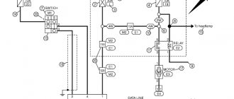
- Functional, it shows the node elements (depicted as rectangles), as well as the communication lines connecting them. A characteristic feature of this scheme is minimal detail. To describe the main functions of nodes, the rectangles displaying them are signed with standard letter designations. These can be various parts of the product that differ in functionality, for example, an automatic dimmer with a photo relay as a sensor or a regular TV. An example of such a scheme is presented below.
Example of a functional diagram of a television receiver - Fundamental. This type of graphic document displays in detail both the elements used in the design and their connections and contacts. The electrical parameters of some elements can be displayed directly in the document, or presented separately in the form of a table.
Example of a circuit diagram of a milling machine
Graphic symbols
Each type of graphic document has its own designations, regulated by relevant regulatory documents. Let us give as an example the basic graphic symbols for different types of electrical circuits.
Examples of UGO in functional diagrams
Below is a picture depicting the main components of automation systems.
Examples of symbols for electrical appliances and automation equipment in accordance with GOST 21.404-85
Description of symbols:
- A – Basic (1) and acceptable (2) images of devices that are installed outside the electrical panel or junction box.
- B - The same as point A, except that the elements are located on the remote control or electrical panel.
- C – Display of actuators (AM).
- D – Influence of MI on the regulating body (hereinafter referred to as RO) when the power is turned off:
- RO opening occurs
- Closing RO
- The position of the RO remains unchanged.
- E - IM, on which a manual drive is additionally installed. This symbol may be used for any RO provisions specified in paragraph D.
- F- Accepted mappings of communication lines:
- General.
- There is no connection at the intersection.
- The presence of a connection at the intersection.
UGO in single-line and complete electrical circuits
There are several groups of symbols for these schemes; we present the most common of them. To obtain complete information, you must refer to the regulatory documents; the numbers of state standards will be given for each group.
Graphic designation of electrical elements on the GOST diagram
Drawings and diagrams of electrical installations are needed for reading by electricians and electricians. The technical document contains schematic information about the size, shape, and composition of electrical equipment. To read, you need to know the common symbols on electrical diagrams that are used to show switches, circuit breakers, motors, rectifiers and other electrical elements in the drawing.
- Types of electrical circuits
- Graphic symbols
- Letter designations
Types of electrical circuits
An electrical diagram is a technical drawing drawn up using symbols used for conventional parts of equipment. The decoding gives an idea of the set of elements in the circuit and the interaction between them. To designate the diagram itself, unlike other drawings, the letter E is used. The rules for decoding are given in GOST 2.702 - 2011 and GOST 2.708 - 81.
Types of electrical circuits:
- Structural. They are compiled during the design process and display the main components of the system (electrical wiring lines, transformers, distribution nodes). This type gives a general idea of the operation of the installation.
- Functional. They contain general diagrams showing the relationship between the components of the object, revealing the essence of the electrical installation. The standards in these schemes are conditional; general standards for the preparation of technological documents are applicable.
- Principled. Shows all magnetic, electrical and electromagnetic connections between elements, characteristics of components. For these schemes there are many standards regarding design and symbols on the drawings.
- Assembly. The drawings contain information about the location of elements outside and inside the installation. Using graphic images, equipment can be manufactured taking into account their correct interaction. General designation requirements apply.
Graphic symbols
Any electrical installation operates under certain conditions, for which symbols have been developed in electrical diagrams.
When reading the drawings, you can obtain the following information:
- conditions for using electrical equipment;
- correspondence between design and real circumstances;
- find unnecessary conditions and evaluate the consequences of their action.
For reading, they use the technique of dividing an electrical circuit into separate circuits and examining them. The simplest schemes are subsequently considered in combination.
Simple circuits include the elements:
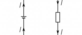
- source of electric current: secondary transformer winding, battery, capacitor, etc.;
- current receiver: lamps, motors, relays, rarefied capacitors;
- return conductor: from the point of analysis to the primary source of current;
- one switching terminal: machine, switch.
Read diagrams using symbols to identify electrical elements on the diagrams. Graphic figures are formed from rectangles, squares, circles, solid and dashed lines, dots, vectors. They are combined in a drawing according to developed standard standards, so you can easily display electrical devices, electrical machines, mechanical and electrical connections, and other combinations and interactions.
In addition to symbols, special graphics are used to show the functionality of the module. For example, for a contact they put an image of closing or opening. There are additional figures on the moving parts to help you find the relay, RCD, and control buttons.
Some parts and assemblies are shown with several variants of graphic icons . For example, this applies to transformer windings or switching contacts. You can use all these options in different cases.
If the standard does not provide an icon for designation , it is created based on the fundamental action of the element. They take into account the signs for similar types of equipment and modules, and pay attention to the principle of constructing the symbols provided for by the standards.
To symbolize electrical boxes, cabinets, panels, control panels on electrical diagrams, the following icons are used:
Sockets, panels, and circuit breakers received the following signs:
Lighting elements, lamps are indicated in accordance with GOST:
In complex circuits of electrical equipment the following signs are used:
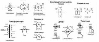
To show chokes and transformers on circuit diagrams, there are graphic images:
Measuring modules are depicted graphically:
For electricians, they show grounding loops and power cables :
The diagrams contain straight and wavy lines, “+” and “-” icons, showing current pulses, type and voltage:
Contact connections are indicated graphically as follows:
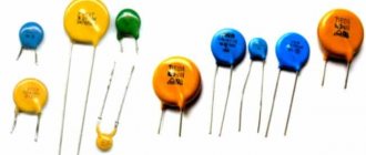
Elements in radio circuits are depicted as follows:
Such graphic elements are used to show all components, nodes, and modules in a circuit. There are many of them, it’s difficult to remember, but you can always refer to specialized electrician reference books.
Letter designations
In single-line electrical diagrams, letters are used to understand the configuration of the network.
Their use is regulated by GOST 76.24 – 55:
- electric relays of voltage, current, resistance, power, intermediate, temporary, gas, index and others have the letter designation RT, RS, RP, RU, RG, RV, RN, RTV, RM and similar;
- control button - KU;
- final breaker - HF;
- team controller - QC;
- travel switch - PV;
- head engine - DG;
- cooling pump motor - BEFORE;
- feed motor - DP;
- high speed motor - DBH;
- spindle motor - DS.
Letter codes are placed next to the element (to the right) or above it . They are combined with graphic icons. In positional letter codes of identical parts, numbers are added according to their quantity.
In domestic electrical circuits, markings are used to designate radio engineering and electrical parts:
Letter designations
In electrical diagrams, in addition to graphic symbols, alphabetic symbols are also used, since without the latter, reading the drawings will be quite problematic. Alphanumeric marking, just like UGO, is regulated by regulatory documents, for electrical this is GOST 7624 55. Below is a table with BO for the main components of electrical circuits.
Letter designations of main elements
Unfortunately, the size of this article does not allow us to provide all the correct graphic and letter symbols, but we have indicated regulatory documents from which all the missing information can be obtained. It should be taken into account that current standards may change depending on the modernization of the technical base, therefore, we recommend monitoring the release of new additions to regulations.
Conventional graphic designation of electric motors in the diagram
In order to draw an electrical circuit, use conventional graphic symbols for all elements. So, in a simplified version, you can depict any element - a resistor, capacitor, electric motor, etc. They are standardized for the main types of elements; in this article we will look at the designations of electric motors in the diagram.
- Graphic designation of electrical machines
- DC motors
- Asynchronous machines
- Synchronous machines
- Generators
- UGO of other types of electrical machines
- Conclusion
Graphic designation of electrical machines
For schematic designation, a special ESKD system was developed, according to which any engine can be displayed on the drawing. It is represented as a circle, next to which a letter designation may be indicated. For example, DG is the main engine, DSh is the machine spindle feed electric motor, DO is the cooling pump, etc. Let's consider which UGOs the system standardizes; their full list is given in GOST 2.722-68
DC motors
DC machines have a symbol depending on the excitation option. The figure shows a DC electric motor with various UGO options.
In addition, there are many devices with additional functions. For example, a reversible electric motor with two windings or with parallel excitation and a vibration speed controller. Below are the UGOs of such devices.
Asynchronous machines
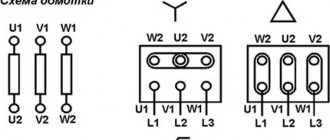
Asynchronous electric motors are depicted in the drawings as a circle, inside which there is a smaller circle representing the rotor.
The illustration shows a graphic designation of an asynchronous electric machine with a squirrel-cage rotor on a single-line diagram. For a three-phase network, the symbolic representation of a phase- and short-circuited motor is performed in a similar way, the only difference being the number of wires and the connection of the rotor circuit.
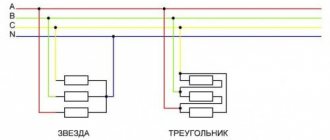
Moreover, if the electric motor is three-phase, the winding connection diagram is indicated. For example, a star connection is indicated as follows:
Each type of three-phase asynchronous machines has a different appearance in the drawing. Below are options for graphic designations of engines of various designs.
Synchronous machines
Synchronous machines according to GOST are presented in the form shown in the illustration below, and the diagram is easy to read even by a non-specialist.
A salient-pole machine with an armature winding is shown in the diagram as two circles, here wires are connected to both the outer and central ones (to the stator and rotor, respectively).
If the windings are connected by a triangle, then the synchronous electric motor will be depicted in the drawing somewhat differently.
The remaining varieties of UGO types of electric motors in the diagrams are presented with a description in the figure below.
Generators
The designation of three-phase generators, as well as synchronous motors, has the same graphic design. Below are the images that appear on the diagram.
UGO of other types of electrical machines
In addition to common devices, special ones are used, which also have their own designation in the diagram.
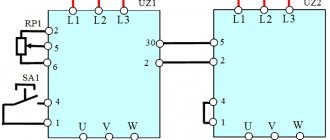
Special devices such as selsyn sensors and receivers have, in addition to a graphic designation, also a letter description, which is illustrated in the figure below.
The motor-converter is shown on the diagram in accordance with the UGO. Its outline on the diagram is shown in the illustration.
Here are devices that have a collector unit. It has a UGO in the form of two rectangles on the sides of a circle.
Conclusion
Graphic designation of electrical machines on diagrams is carried out in accordance with GOST 2.722. When drawing up a diagram, you must be guided by this documentation. It describes all the necessary machines, and also indicates the dimensions of the circle and other elements of the drawing that should be on the drawings and other requirements for the drawing.