A device that is triggered upon expiration of a designated time interval is called a time relay - the device is widely used in electrical engineering, electrical engineering, and electronics. Thanks to its use in circuit solutions, it is possible to implement more flexible control functions for various equipment and devices.
Depending on the design and operating principle of the device, electrical circuits of varying complexity can be organized.
We propose to understand what types of time relays exist, what are their specific features of operation and application. The theoretical material is supplemented with practical recommendations for connecting and setting up a temporary control device.
Purpose
The time relay is designed to form standardized time delays during the operation of any devices. Such logical elements allow you to build a certain sequence in switching and operating devices. Thanks to the delayed supply of voltage, the signals issued from the time relay are automatically controlled.
Time relays are installed in protection circuits as an intermediate element to ensure selectivity, build stages, scenario transitions, etc.
Operating algorithms, functional diagrams, symbols
Functional diagram of a two-channel time relay
Modern programmable devices provide a complex operating algorithm, including time pauses and cyclically repeating intervals. There are the following operating schemes for time relays:
- simple switch-on delay;
- after power is applied, the load is connected, but after a time specified by the program, the voltage is removed from it;
- the same as in the previous case, but the shutdown occurs with some delay.
Another scheme assumes a more complex cyclic mode of operation of the device. To understand it, you should clarify the procedure for turning on and off the load. It looks like this:
- After supply, the food arrives as intended only after a certain period of time.
- The line remains connected to the network for a predefined interval.
- There is a shutdown and a pause equal to its duration when power is applied.
- The load is reconnected for the same time as the first time.
- The sequence of these actions continues until the supply voltage is completely removed.
When studying the algorithms for operating a time relay and the features of its application, you will need to become familiar with one of the most important characteristics of the device, presented in the form of a functional diagram.
Trigger diagrams
Diagrams of operation of a time relay
This characteristic refers to graphic diagrams that describe the state of a time relay at different points in time. When you get acquainted with them, the entire switching process is presented in a visual form.
The cyclic nature of the processes observed when devices operate according to a complex algorithm is especially clearly distinguishable in the diagrams. The time intervals indicated on them are usually set by the user himself. On the other hand, there are known examples of devices in which the moments of disconnecting and connecting the load cannot be adjusted. As a fixed parameter, they are usually indicated in the product passport. Most often, these are special-purpose timing devices installed in the protective circuits of industrial installations.
Each individual time relay sample provides several operating algorithms, selected at the discretion of the user. The appearance of the functional diagrams is shown on the product body, where you can also familiarize yourself with the location of its contacts.
Contact designations on diagrams
Graphic designation of contacts
When choosing a time relay, it is important to learn to understand not only the functional response diagrams, but also the layout of its working contacts. Among them, the following types of contact groups stand out:
- one of them is always open in the non-working position;
- the other group of contacts is in a closed state under normal conditions;
- the third variety has a neutral position.
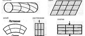
To understand the nature of relay operation in the diagrams, they are indicated by special icons in the form of semi-ovals, straight line segments and truncated parallels.
Design and principle of operation
Structurally, a time relay consists of several elements, the number and functions of which can vary significantly depending on the type of relay. Common blocks are the measuring block, the delay block and the working block.
- The first of them is represented by electromagnetic coils, semiconductor elements, microcircuits that respond to incoming electric current signals.
- The delay block is performed by a clock mechanism, a bridge, an electromagnetic or pneumatic damper.
- The working element is the contacts or output from an analog or digital circuit that controls the supply of voltage to certain circuits.
Depending on the design features of a particular model, the principle of its operation will differ.
The principle of operation of a time relay is to create a time interval from the start of a signal to the time relay until the consumer receives this signal. Further operations and the supply of power to the working element will differ radically depending on the type of device, so the principle of operation should be considered for each type of time relay separately.
With electromagnetic retardation
Structurally, such a time relay consists of an electromagnetic coil, a magnetic core (yoke), a movable armature, a short-circuited sleeve and a shutdown unit, which are shown in the figure below:
Rice. 1: electromagnetic relay design
The operating principle of an electromagnetic relay is to create a magnetic flux in the magnetic core, induced from a coil. The magnetic flux attracts the armature with contacts. But, in this mode of operation, the device would be a regular intermediate relay, so a sleeve is used to delay the closure of the contacts. It creates in a short-circuited circuit an electromagnetic flux that is counter-directional, delaying the increase in the main one and causing the time interval to be maintained.
As a rule, in electromagnetic models the delay is from 0.07 to 0.15 seconds; the device operates from DC circuits.
With pneumatic retardation
This type is used in machine tools in various industries; in some cases, hydraulic models are also found. Such a time relay consists of a working coil mounted on a magnetic circuit, contacts and a pneumatic membrane or diaphragm that acts as a damper.
Rice. 2: pneumatic relay design
The principle of operation of a pneumatic time relay is that when voltage is applied to the winding, a magnetic flux appears in the core, causing it to move. But instantaneous transfer of contacts does not occur due to the presence of an air gap under the membrane. The turn-on delay time will be determined by the amount of air in the damper and the rate at which it is removed. To adjust this parameter, pneumatic models provide a screw that increases or decreases the volume of the chamber or the width of the outlet valve.
With anchor or clock mechanism
The design difference between a time relay and a clock mechanism is the presence of a spring device, which is wound by an electric drive or manually. The response delay for it is determined by the position of the closing flag on the dial.
Rice. 3: clock relay design
When a control signal appears, the mechanism is released, and the spring slowly moves the working element, rotating along the dial scale. When the set mark is reached, the load is turned on by closing a pair of contacts. The time delay limits can be selected using special clamps or by setting an adjustable knob to a specific position. The exact control method will vary depending on the model and manufacturer.
Motor time relay
A distinctive feature of motor relays is the presence of their own motor, which is activated together with the coil. The operating principle of such a device is shown in the figure below:
Rice. 4: motor relay design
Voltage is supplied to an electrical circuit consisting of coil 1 and synchronous motor 2. After exciting the stator windings in the motor, its shaft drives a gear system 3 and 4, usually consisting of several gears. Rotation of the motor relay gears results in mechanical pressure on the lever that presses the contacts. The shutter speed range is adjusted by moving the lock 8.
Electronic time relays
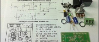
Modern electronic relays are an automatic switch, the principle of supplying a signal from the output of which is regulated by the setting of the R - C chain, the parameters of microcircuits or semiconductor elements. The simplest option is to work together with a capacitor and a resistor, shown in the figure below:
Rice. 5: electronic relay logic chain principle
Depending on the ratio of the ohmic resistance of the resistor and the capacitance of the capacitor, the charging time of the latter will determine the supply of supply voltage to the electronic device. This example shows the simplest version of a timing chain; modern models may contain more complex structures, including several R - C branches or their combinations with transistors, bridges and other elements. Electronic models have a number of significant advantages compared to other types of relays:
- Relatively smaller sizes;
- High accuracy;
- Wide range of adjustment – from tenths of seconds to hours or days;
- Automatic control – convenient programming system and its visual display on the display.
These advantages lead to the widespread replacement of other outdated models by electronic relays.
Cyclical
By cyclic time relays we mean devices that produce a control signal after a given period of time (for heating a kettle, opening windows in the morning, turning on an alarm at night, etc.). Such automatic switching has a certain scenario that is repeated after a certain period of time, which is why this group of devices is also called scenario switches. Previously, cyclic switching was carried out using a mechanical spring device; today this function has been transferred to microprocessor elements. Electronic timers are widely used in a variety of fields, some of which are shown in the figure:
Rice. 6: Scope of application of cyclic relays
Types and classification
The following types of counting time intervals are used, according to which the classification of time-setting devices is made:
- pneumatic;
- motor;
- electromagnetic;
- sentries (anchors);
- electronic.
The next difference lies in the value of the supply voltage of the control electromagnet, which carries out the initial platoon of the actuator or mechanism, and the electromagnet that controls the switching of the output terminals. The most common types of voltage time relays are:
- 12V DC voltage;
- 24 VDC;
- 220 volts AC.
How to choose?
When choosing a specific time relay model, you must be guided by the following principles regarding their parameters:
- Type and value of operating voltage - various models can either be connected to a household network of 220 V AC, or operate from reduced control circuits of 12, 42, 127 V, etc.
- Allowable load current – determines the capacity of the time relay contacts without overheating.
- The range of contact response times and the sensitivity of adjusting this parameter determines the speed at which the time relay is switched on, the possibility of changing it within any limits and the possible adjustment step.
- Design features and principle of operation - if local conditions do not allow classical switching of contacts for reasons of explosion hazard, it is necessary to install contactless models.
- Moisture resistance and temperature range - determines the permissible environmental parameters in which this time relay can be operated.
- Type of device (cyclic or intermediate) - the first of them sets a certain periodicity of the output signal, and the second acts as an intermediate link that provides a time delay in an already existing circuit.
Adjusting instruments with a digital scale
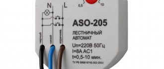
The use of devices with mechanical adjustment functions can be demonstrated using the example of a household timer from the REV Ritter , designed to be plugged into a home power outlet.
The so-called “socket” relay, intended for use in domestic conditions. The duration of action is usually limited to a daily range. This time is quite enough for household use.
Using a socket with a timer, you can control almost any household appliance within a given time range. To use this daily timer, just plug the device into a power outlet and set it up.
The setup is accompanied by the following actions:
- Raise all segments located around the circumference of the tuning dial.
- Omit only those segments that correspond to the setup time.
- Turn the dial to set the dial pointer to the current time.
For example, if the segments between the scale numbers 18 and 20 were omitted, after the relay starts timing, the load will be turned on at 18 o'clock and off at 20 o'clock.
In general, the design of the REV Ritter mechanical relay allows up to 48 activations in a full 24 hours.
Modification of a “socket” time relay: 1 – load connection socket; 2 – manual control; 3 – scale marked at 24 hours; 4 – program segments; 5 – current time indicator; 6 – power plug into a household outlet (+)
At the same time, the device supports the function of out-of-program load switching. For this purpose there is a separate button located on the side of the case. If the user activates this button, the load is connected to the network directly, regardless of the state of the relay contacts.
Examples of connection diagrams
Depending on the specific model of the time relay or the tasks it must solve, the connection diagram may differ radically.
Rice. 7: connection diagram example
Look at Figure 7; this example shows one of the simplest options for controlling lighting fixtures using a time relay. The control signal is supplied to pins 1 and 2, and to the load from pin 3 and the neutral wire. Terminal 4 receives power from a 220V network. This scheme is widely used for domestic needs and is practically not used for industrial purposes, since it ensures operation with only one consumer (lighting device, line, alarm, etc.).
Rice. 8: Another time relay connection diagram
Figure 8 shows a diagram for connecting a time relay; here the power supply method is similar to the previous diagram. But at the output of the device, two independent groups of consumers are connected from pins 3 and 5, which can have individual operating logic. This connection method provides much greater functionality, due to which it is used in places where control of several devices at once is required.
Rice. 9: circuit for switching on a relay via a contactor
As you can see in Figure 9, when connecting powerful equipment for which a time relay cannot supply it with power due to insufficient conductivity of its own circuits, a logical element is connected via a power contactor. In this scheme, the working element is a contactor, the control signal to which is supplied from the contacts of a time relay. The main advantage of this connection scheme is the ability to power a consumer of any power and operating principle.
Configuring electronic-mechanical analog relays
Industrial automation systems, as well as various household modules, are often equipped with electromechanical devices, the design of which allows for adjustment using potentiometers.
Electromechanical type of time counting device with parameter adjustment by potentiometers. There are various configurations of such devices, which makes it possible to use them in circuits of varying complexity.
On the front panel of the housing of such devices there is a potentiometer rod (or several rods) designed for rotation with a screwdriver blade. A marked scale of installation values is applied around the circumference of the rod(s).
The slot on the rod for the screwdriver blade is a kind of pointer that changes its position when the rod rotates. By placing this pointer opposite certain values of the marked scale, the desired parameter can be adjusted.
Multichannel device of electronic-mechanical type. Adjustment is easy and simple by rotating the potentiometers with a screwdriver. The front panel also has LED status indication
Devices of this type (for example, NTE8 ) are widely used in control circuits for ventilation systems, heating modules, and artificial lighting devices.
List of used literature
- Figurnov E. P. “Relay protection” 2004
- Iglovsky I. G., Vladimirov G. V. “Handbook on low-current electrical relays” 1984
- Filipcheiko I, P., Rybin G. Ya. “Electromagnetic relays” 1968
- Gurevich V.I. "Electrical relays. Device, principle of operation and application. Engineer's Handbook" 2011
- Andreev V.A. “Relay protection of power supply systems in examples and tasks” 2008
- Bass E.I., Doroguntsev V.G. “Relay protection of electric power systems” 2002
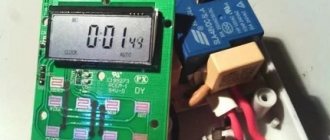
Weekly digital timer
A digital weekly timer or electronic time relay is a flexible, programmable device designed to operate within seven calendar days. With its help, it is possible to set the exact dates of necessary switching (connections or disconnections of specific loads) in public institutions such as schools, offices and similar places of collective use.
“Advanced” samples of daily time relays provide the ability to save copies of several programs with the ability to read them. Various types of drives are used as storage media, allowing it to be removed using an electronic key D KEY (in the PLUS and SYNCHRO system versions).
Varieties by design
Depending on the design features, there are three manufacturing options, as can be seen in the photo of the time relay:
- Block - have an external type of installation. The peculiarity lies in the internal power supply of the device. This design feature is inherent in relays installed in devices that perform photo printing.
- Built-in is a simpler model without a housing and independent power supply. They are used when assembling more complex units and are built into the body of the units together with other components, as on washing machines.
- Modular – characterized by the possibility of mounting in electrical panels using a DIN rail.
Photo of time relay
Read here! How to connect machines - do-it-yourself connection and installation instructions. Recommendations from experts + video
Electromagnetic
It is used only in electrical circuits with direct current and includes components such as a magnetic conductor element, a control type winding, and a short-circuited turn.
The delay in switching is created due to the short-circuited winding. It contains one turn, which is fixed on the core component of the magnetic circuit. This turn has the appearance of a sleeve. It is made from metal - aluminum or copper.
To provide a delay interval for operation, an auxiliary magnetic flux is provided. Adjustment is possible by changing the gap parameters or the tension of the return spring. Adjustable within 5 s.
The relay is common in circuits that control the acceleration or braking of an electric drive. The time delay is affected by temperature. If the winding temperature deviates by 10°C, then the delay changes by 4%.
Settings
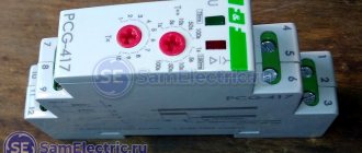
If you are new to logic time relays (such as TDR1, TDR26 and TDR 60s), setting them up may seem strange and complicated, but engineer Rick explains everything simply and clearly.
The presented devices have power and control terminals. In addition to the terminals, the device has three mechanical switches, which are responsible for setting the delay until the moment of operation and the operating mode. If a turn-on delay is configured, the device begins supplying power to the load only after the specified time has elapsed. In the event of a switch-off delay, the relay operates in the reverse order.
To adjust the response delay time, you must first select the appropriate range, then the multiplier. For example, to set the trigger to 30 seconds, you need to: set the range value to 10 s, and set the multiplier to 30.
Location of controls on the product
How does a time relay work?
The principle of operation of a time relay is similar to the operation of a conventional relay, where the contact group ensures that the device operates.
Analog relays are distinguished by the presence of a clock mechanism that controls the contacts. Inside digital relays there is an electromagnetic coil that receives current to fix the magnetic armature using an electronic timer.
The operating procedure of analog relays is comparable to the method of setting an alarm in a mechanically wound watch. The mechanically installed cuckoo pops up clearly demonstrates the daily cyclical functioning of the programmed relay.
All electronic and many analog devices use a quartz-based pulse generator to detect the passage of time. The generated signals are taken into account in a mechanical or electronic counting device.
It is set to a certain number. Once the number is reached, some programmed action is carried out. At the same time, the counter is set to zero, and a new countdown of incoming pulses to the programmed number begins.
- Details about scissor lift
- How to choose a monument?
Why do you need online personnel testing?
Electronic
To understand how to connect a time relay, you need to know that two types of solutions are possible regarding the circuit:
Analog group relay - delay is produced by switching action relative to the capacitor. When the contacts close, the voltage across the capacitor section increases.
\
The existing device monitors the change in voltage and makes a comparison with a given parameter. As soon as the voltage converges, the threshold element gives the command to switch the relay. By changing the capacitance of the capacitor, you can adjust the delay. It is maximum 10 seconds.
Digital relays - it is assumed that voltage is supplied to a special power supply. As a result, the master action generator is activated. It sends pulse signals to the counter. The latter monitors the pulses and monitors the moment of coincidence with the initially specified parameter.
If there is a match, a signal is given. It goes to the output amplifier, which regulates the operation of the relay. After the voltage is removed from the power supply, the relay returns to its original state. The delay varies widely.
Reinforcing shears (bolt cutters): types, characteristics, main differencesHow a voltage control relay works: the principle of operation of the protection and the nuances of connecting a control relay for a house or apartment
- What is a pulse relay: principle of operation, types, description of devices and connection diagrams. 155 photos of pulse-type relays and video installation instructions
Electronic devices are compact, reliable, and have high accuracy values. While analog models are easy to use and do not require programming, digital models have a small error, but are quite expensive. Electronic relays are widely used in control systems for the supply of water, electricity, and coolant.
Motor
A time relay, along with an electromagnet and a contact group, contains a motor and a gearbox in its design. When the device is triggered, voltage is supplied to the synchronous motor and electromagnet.
The engine drives the discs through a clutch and gear drive. Their design contains cams. They have an effect on contacts. The time delay is adjusted by changing the position of the disks. Delay period from 10 sec. up to several hours.
UPS for home: types, design and operating features- What is an intermediate relay: design, principle of operation, device and application ideas (115 photos)
Homemade 12 volt power supply: selection of components and simple circuits for creating with your own hands. 130 photos of homemade universal blocks