In order to obtain electricity directly from a gas burner or other heat source, a thermogenerator is used. Just like a thermocouple, its operating principle is based on the Seebeck effect, discovered in 1821. The mentioned effect is that in a closed circuit of two dissimilar conductors an EMF appears if the junctions of the conductors are at different temperatures. For example, one junction is in a vessel with boiling water, and the other is in a cup of melting ice.
The effect arises from the fact that the energy of free electrons depends on temperature. In this case, electrons begin to move from the conductor, where they have higher energy, to the conductor, where the energy of the charges is lower. If one of the junctions is heated more than the other, then the energy difference between the charges on it is greater than on the cold one. Therefore, if the circuit is closed, a current arises in it, precisely the same thermopower.
The approximate value of thermopower can be determined using a simple formula:
E = α * (T1 – T2). Here α is the thermopower coefficient, which depends only on the metals of which the thermocouple or thermoelement is composed. Its value is usually expressed in microvolts per degree. The temperature difference between the junctions in this formula (T1 – T2): T1 is the temperature of the hot junction, and T2, respectively, the cold junction.
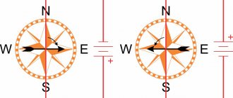
The above formula is quite clearly illustrated in Fig. 1.
Rice. 1. Operating principle of thermocouple
This drawing is classic, it can be found in any physics textbook. The figure shows a ring made up of two conductors A and B. The junctions of the conductors are called junctions. As shown in the figure, in the hot junction T1 the thermopower is directed from metal B to metal A. And in the cold junction T2 from metal A to metal B. The direction of the thermopower indicated in the figure is valid for the case when the thermopower of metal A is positive with respect to metal B .
DIY making
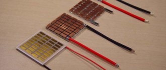
Schematically, the structure of a homemade thermoelectric power plant can be represented as follows:
- We place the Peltier element at the bottom of a deep vessel - a bowl or mug.
- Next, we’ll insert another one into this vessel: if bowls are used, you’ll need the same one; if your choice fell on mugs, then the second one should be slightly smaller than the first.
- We will connect a voltage converter to the wires removed from the Peltier element.
- Fill the inner vessel with snow or cold water, after which we put the entire structure on the fire.
After some time, the snow will melt, turn into water and boil. The productivity of the generator will decrease, but the tourist will have the opportunity to drink hot tea. After drinking tea, you can fill the generator with a new portion of snow.
The more thermoelements (they are also called branches) the Peltier element you purchased has, the better. You can use a device brand TEC1-127120-50 - it has 127 of them. This element is designed for currents up to 12A.
Household thermogenerator
Already in the post-war fifties, Soviet industry began to produce the TGK-3 thermogenerator. Its main purpose was to power battery-powered radios in unelectrified rural areas. The generator power was 3 W, which made it possible to power battery receivers such as “Tula”, “Iskra”, “Tallinn B-2”, “Rodina - 47”, “Rodina - 52” and some others.
The appearance of the TGK-3 thermogenerator is shown in Fig. 3.
Rice. 3. Thermal generator TGK-3
Thermal generator design
As already mentioned, the thermogenerator was intended for use in rural areas, where lightning kerosene lamps were used for lighting. Such a lamp, equipped with a thermogenerator, became not only a source of light, but also electricity. At the same time, no additional fuel consumption was required, because exactly that part of the kerosene that simply flew into the chimney was converted into electricity. In addition, such a generator was always ready for work; its design was such that there was simply nothing to break in it. The generator could simply lie idle, work without load, and was not afraid of short circuits. The service life of the generator, compared to galvanic batteries, seemed simply eternal.
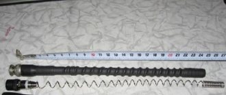
The role of the exhaust pipe of a lightning kerosene lamp is played by an elongated cylindrical part of the glass. When using a lamp together with a thermal generator, the glass was made shortened, and a metal heat transferr 1 was inserted into it, as shown in Fig. 4.
Rice. 4. Kerosene lamp with thermoelectric generator
The outer part of the heat transferr has the shape of a multifaceted prism on which thermopiles are installed. To increase the efficiency of heat transfer, the heat transferr inside had several longitudinal channels. Passing through these channels, hot gases went into exhaust pipe 3, simultaneously heating the thermopile, or rather, its hot junctions. An air-cooled radiator was used to cool the cold junctions. It consists of metal fins attached to the outer surfaces of thermopile blocks.
The thermogenerator – TGK3 consisted of two independent sections. One of them produced a voltage of 2V at a load current of up to 2A. This section was used to obtain the anode voltage of the lamps using a vibration transducer. Another section with a voltage of 1.2V and a load current of 0.5A was used to power the filaments of the lamps.
It is easy to calculate that the thermal generator had a power not exceeding 5 Watts, but it was quite enough for the receiver, which made it possible to brighten up long winter evenings. Now, of course, this seems simply ridiculous, but in those distant times such a device was undoubtedly a miracle of technology.
How thermogenerators were created
Already in the middle of the 19th century, numerous attempts were made to create thermogenerators - devices for generating electrical energy, that is, for powering various consumers. Batteries made of series-connected thermoelements were supposed to be used as such sources. The design of such a battery is shown in Fig. 2.
Rice. 2. Thermopile, schematic device
The first thermoelectric battery was created in the mid-19th century by physicists Oersted and Fourier. Bismuth and antimony were used as thermoelectrodes, precisely the same pair of pure metals that have the maximum thermopower. The hot junctions were heated with gas burners, and the cold junctions were placed in a vessel with ice. During experiments with thermoelectricity, thermopiles were later invented, suitable for use in some technological processes and even for lighting. An example is the Clamont battery, developed in 1874, the power of which was quite sufficient for practical purposes: for example, for electroplating, as well as for use in printing houses and heliogravure workshops. Around the same time, the scientist Noe was also researching thermopiles; his thermopiles were also quite widespread at one time.
But all these experiments, although successful, were doomed to failure, since thermopiles created on the basis of thermoelements made of pure metals had very low efficiency, which hampered their practical use. Purely metallic pairs have an efficiency of only a few tenths of a percent. Semiconductor materials have much greater efficiency: some oxides, sulfides and intermetallic compounds.
Semiconductor thermoelements
A true revolution in the creation of thermoelements was made by the works of Academician A.I. Ioffe. In the early 30s of the 20th century, he put forward the idea that with the help of semiconductors it was possible to convert thermal energy, including solar energy, into electrical energy. Thanks to the research carried out, already in 1940 a semiconductor photocell was created to convert solar light energy into electrical energy. The first practical application of semiconductor thermoelements should be considered, apparently, the “partisan pot”, which made it possible to provide power to some portable partisan radio stations.
The thermogenerator was based on elements made of constantan and SbZn. The temperature of the cold junctions was stabilized by boiling water, while the hot junctions were heated by the flame of a fire, while ensuring a temperature difference of at least 250...300 degrees. The efficiency of such a device was no more than 1.5...2.0%, but there was enough power to power radio stations. Of course, in those wartime times, the design of the “pot” was a state secret, and even now its structure is discussed on many forums on the Internet.
Work order
Now let's look at the process of creating a homemade thermal generator in detail:
- The surface of each vessel at the point of contact with the Peltier element should be leveled and cleaned, which will ensure maximum heat transfer. For a perfect fit, you can polish the bottoms with a piece of felt greased with GOI paste, fixed in the spindle of an electric drill.
- We connect wires from an electric stove equipped with heat-resistant insulation to the contacts of the Peltier element. In the absence of such, you can use, for example, MGTFE-0.35 wire, wrapping it in heat-resistant fabric.
- Having lubricated the bottom of one of the vessels with thermal conductive paste, for example, KPT-8, we place a Peltier element on it. The wires connected to it should be positioned so that their ends are outside the container.
- Lubricate the Peltier element on top with thermal paste again and insert a second container of a suitable size into our mug or bowl (you will need to cut off the handle of the mug).
- The space between the containers must be filled with heat-resistant sealant (you can buy a composition for repairing exhaust pipes at a car store). It will serve as thermal insulation between the hot and cold sides of the generator and additional protection for the wires.
Camping electricity generator
The protruding ends of the wires can be glued to the side of the mug with fabric tape.
Converter manufacturing
During the experiment, a thermogenerator installed on an electric stove, in the presence of snow in the internal container, provided an EMF of 3V and a current of 1.5A. After the snow turned into water and boiled, the power of the generator dropped three times (the voltage was 1.2V).
To use such a device as a charger for a phone or other gadget that requires a stable voltage of 5 V or 6.5 V, it must be equipped with a voltage converter.
Let's consider two options.
Option 1
The easiest way is to use the KR1446PN1 microcircuit, equipped with a DIP housing, as a converter.
It is produced in Russia and can be easily found in a radio parts store or on the radio market.
It is not forbidden to use more powerful analogues, but they are all produced in miniature surface-mount packages, so you will have to suffer with desoldering.
The input of the microcircuit is supplied with voltage from the Peltier element, and it turns on in the “5 Volt” (standard) mode. In parallel with the Peltier element, a sufficiently powerful shunt diode should be soldered to the input of the voltage converter. It will prevent current from flowing in the opposite direction if the generator is exposed to the opposite temperature effect.
For example, being filled with hot water, it can be inadvertently installed on some cold surface.
To the output of the converter you need to solder a cable from an old charger suitable for our model of phone or camera, as well as a 5 V LED indicator.
The disadvantage of this option: the microcircuit proposed as a converter limits the power of the generator, since the current at its output does not exceed 100 mA. Thus, the Peltier element is used by approximately 20%, which will only be sufficient for older models of phones.
To be able to charge more powerful devices, you need to use a more sophisticated version of the voltage converter.
Option 2
A more powerful converter can be assembled using a two-stage circuit using a pair of MAX 756 microcircuits. So that when the consumer is disconnected, the generated current does not go to waste, we will equip the converter with built-in batteries. Connected in series, they are included in the load of the first stage through a switch, diode and current-limiting resistor. The cascade itself is configured for the “3.3 Volt” output mode.
To the output of cascade No. 1 we connect cascade No. 2, configured to the “5 Volt” output mode. Both stages are implemented according to the diagram given in the documentation for the MAX 756 chip (published on the Internet). The only difference is that the feedback circuit of cascade No. 2 (between the output of the cascade and leg No. 6 of its microcircuit) is supplemented by a sequence of 3 silicon diodes located with the anode towards the output.
The simplest camping thermogenerator
This improvement will allow you to receive a voltage of 6.5 V at idle (required for charging some electronic devices).
To simplify the circuit, you can use the MAX 757 chip, which is equipped with a separate feedback output.
The interface of this converter corresponds to USB Type A. But if you intend to connect a USB device to it, then it is better to remove the sequence of diodes from the feedback circuit of the 2nd stage so that the output voltage returns to the level of 5 V.
This version of the converter cannot be connected to USB-Host type ports.
Variation on a theme...
The Peltier element can simply be attached to a stake stuck into the ground near the fire.
To create a sufficient temperature gradient, both surfaces must be equipped with finned radiators.
On the surface on the flame side, the radiator should have an increased area, and its fins should be installed horizontally.
A smaller radiator is installed on the opposite side of the element, and its fins are vertical.
Heating radiators can be installed differently depending on the type of heating system - single-pipe or two-pipe. Read the heating radiator connection diagrams and tips on where to install them carefully.
How to repair a circulation pump with your own hands? The main types of breakdowns and methods for eliminating them are presented in this article.