High-voltage (HV) capacitors are devices widely used in electrical circuits of various devices and equipment under very high voltage. Unlike low-voltage analogues, they have a reliable design, a long service life, and high cost. What such devices are, what types they are, how they work and where they are used will be discussed in this article.
High voltage capacitor
Assembling the device
Let's start with etching the board (etching, stripping, drilling). Download the archive from the software here.
First I bought some missing parts (transistors, IR, and powerful resistors).
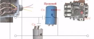
By the way, the surge protector was completely removed from the power supply from the disc player:
Next, carefully solder the parts on the board according to the diagram and PP.
Now the most interesting thing about the SMPS is the transformer, although there is nothing complicated here, you just need to understand how to wind it correctly, and that’s all. First you need to know what and how much to wind; there are many programs for this, but the most widespread and popular among radio amateurs is ExcellentIT. This is where we will calculate our transformer.
As you can see, we have 49 turns of the primary winding, and two windings of 6 turns each (secondary). Let's rock!
Voltage converter 1.5 V/-9 V
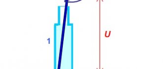
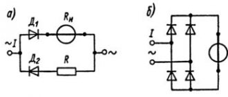
Rice. 8. 1.5 V/-9 V voltage converter circuit.
The converter (Fig. is a single-cycle relaxation generator with capacitive positive feedback (C2, C3). A step-up autotransformer T1 is included in the collector circuit of transistor VT2.
The converter uses reverse connection of the rectifying diode VD1, i.e. when transistor VT2 is open, supply voltage Un is applied to the winding of the autotransformer, and a voltage pulse appears at the output of the autotransformer. However, the reverse-connected diode VD1 is closed at this time, and the load is disconnected from the converter.
At the moment of pause, when the transistor closes, the polarity of the voltage on the windings T1 is reversed, the diode VD1 opens, and the rectified voltage is applied to the load.
In subsequent cycles, when transistor VT2 is turned off, the filter capacitors (C4, C5) are discharged through the load, allowing direct current to flow. In this case, the inductance of the step-up winding of the autotransformer T1 plays the role of a smoothing filter choke.
To eliminate the magnetization of the autotransformer core by the direct current of transistor VT2, magnetization reversal of the autotransformer core is used by connecting capacitors C2 and C3 in parallel with its winding, which are also a feedback voltage divider.
When transistor VT2 closes, capacitors C2 and C3 are discharged through part of the transformer winding during a pause, reversing the magnetization of core T1 with the discharge current.
The generation frequency depends on the voltage at the base of the transistor VT1. Stabilization of the output voltage is carried out due to negative feedback (NFB) for constant voltage through R2.
As the output voltage decreases, the frequency of the generated pulses increases with approximately the same duration. As a result, the frequency of recharging filter capacitors C4 and C5 increases and the voltage drop across the load is compensated. As the output voltage increases, the generation frequency, on the contrary, decreases.
So, after charging the storage capacitor C5, the generation frequency drops tens of times. Only rare pulses remain, compensating for the discharge of capacitors in rest mode. This stabilization method made it possible to reduce the quiescent current of the converter to 0.5 mA.
Transistors VT1 and VT2 should have the highest possible gain to increase efficiency. The winding of the autotransformer is wound on a K10x6x2 ferrite ring made of 2000NM material and has 300 turns of PEL-0.08 wire with a tap from the 50th turn (counting from the “grounded” terminal). Diode VD1 must be high-frequency and have low reverse current. Setting up the converter comes down to setting the output voltage to -9 V by selecting resistor R2.
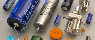
Radio elements from old equipment: capacitors
The second indispensable element in electrical circuits is a capacitor . They are polar and non-polar. Their differences are that some are used in DC voltage circuits, while others are used in AC circuits. It is possible to use permanent capacitors in alternating voltage circuits when they are connected in series with like poles, but they do not show the best parameters.
Non-polar capacitors
Non-polar, just like resistors, can be fixed, variable or adjustable.
Trimmer capacitors are used to tune resonant circuits in transmitting and receiving equipment.
Rice. 1. PDA capacitors
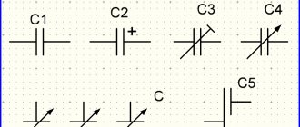
PDA type. They consist of silver-plated plates and a ceramic insulator. They have a capacity of several tens of picofarads. It can be found in any receivers, radios and television modulators. Trimmer capacitors are also designated by the letters KT. Then follows a number indicating the type of dielectric:
1 - vacuum; 2 - air; 3 - gas-filled; 4 - solid dielectric; 5 - liquid dielectric. For example, the designation KP2 means a variable capacitor with an air dielectric, and the designation KT4 means a tuning capacitor with a solid dielectric.
Rice. 2 Modern trimming chip capacitors
To tune radio receivers to the desired frequency, variable capacitors (VCA)
Rice. 3 Capacitors KPE
They can only be found in transmitting and receiving equipment
1- KPE with an air dielectric, can be found in any radio receiver of the 60s-80s. 2 - variable capacitor for VHF units with vernier 3 - variable capacitor, used in receiving equipment of the 90s to this day, can be found in any music center, tape recorder, cassette player with a receiver. Mostly made in China.
There are a great many types of permanent capacitors; within the framework of this article it is impossible to describe all their diversity; I will only describe those that are most often found in household equipment.
Rice. 4 KSO capacitor
KSO capacitors - Pressed mica capacitor. Dielectric - mica, plates - aluminum coating. Filled in a brown compound housing. They are found in equipment from the 30s to the 70s, the capacity does not exceed several tens of nanofarads, and is indicated on the housing in picofarads, nanofarads and microfarads. Thanks to the use of mica as a dielectric, these capacitors are capable of operating at high frequencies, since they have low losses and have a high leakage resistance of about 10^10 Ohms.
Rice. 5 Capacitors KTK
KTK capacitors - Tubular ceramic capacitor. A ceramic tube and silver plates are used as a dielectric. Widely used in oscillatory circuits of lamp equipment from the 40s to the early eighties. The color of the capacitor indicates TKE (temperature coefficient of change of capacitance). Next to the container, as a rule, the TKE group is written, which has an alphabetic or numerical designation (Table 1.) As can be seen from the table, the most heat-stable ones are blue and gray. In general, this type is very good for HF equipment.
Table 1. TKE marking of ceramic capacitors
When setting up receivers, you often have to select capacitors for the local dyne and input circuits. If the receiver uses KTK capacitors, then selecting the capacitance of the capacitors in these circuits can be simplified. To do this, several turns of PEL 0.3 wire are wound tightly onto the capacitor body next to the terminal and one of the ends of this spiral is soldered to the terminal of the capacitors. By spreading and shifting the turns of the spiral, you can adjust the capacitance of the capacitor within small limits. It may happen that by connecting the end of the spiral to one of the terminals of the capacitor, it is not possible to achieve a change in capacitance. In this case, the spiral should be soldered to another terminal.
Rice. 6 Ceramic capacitors. Soviet ones at the top, imported ones at the bottom.
Ceramic capacitors are usually called “red flag” capacitors, sometimes called “clay” capacitors. These capacitors are widely used in high frequency circuits. Typically, these capacitors are not quoted and are rarely used by hobbyists, since capacitors of the same type can be made of different ceramics and have different characteristics. Ceramic capacitors gain in size but lose in thermal stability and linearity. Capacity and TKE are indicated on the body (Table 2.)
table 2
Just look at the permissible change in capacitance for capacitors with TKE N90, the capacitance can change almost twice! For many purposes this is not acceptable, but still you should not reject this type; with a small temperature difference and not strict requirements, they can be used. By using parallel connection of capacitors with different TKE signs, it is possible to obtain a fairly high stability of the resulting capacitance. You can find them in any equipment; the Chinese are especially fond of them in their crafts.
They have a capacity designation on the body in picofarads or nanofarads; imported ones are marked with a numerical code. The first two digits indicate the capacitance value in picofarads (pF), the last two digits indicate the number of zeros. When the capacitor has a capacitance of less than 10 pF, the last digit may be "9". For capacitances less than 1.0 pF, the first digit is “0”. The letter R is used as a decimal point. For example, code 010 is 1.0 pF, code 0R5 is 0.5 pF. Several examples are collected in the table:
Alphanumeric marking: 22р-22 picofarads 2n2- 2.2 nanofarads n10 - 100 picofarads
I would like to especially note ceramic capacitors of the KM type, they are used in industrial equipment and military devices, they have high stability, they are very difficult to find because they contain rare earth metals, and if you find a board where this type of capacitor is used, then in 70% of cases they were cut out before you).
In the last decade, radio components for surface mounting have very often begun to be used; here are the main standard sizes of housings for ceramic chip capacitors
MBM capacitors are a metal-paper capacitor (Fig. 6), usually used in tube sound amplification equipment. Now highly prized by some audiophiles. This type also includes military-grade K42U-2 capacitors, but they can sometimes be found in household equipment.
Rice. 7 Capacitor MBM and K42U-2
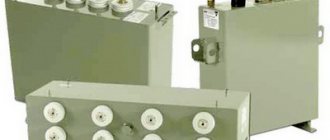
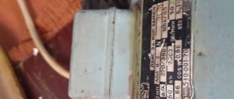
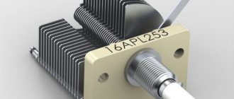
It should be noted separately that such types of capacitors as MBGO and MBGCh (Fig. 8), are often used by amateurs as starting capacitors to start electric motors. As an example, my engine reserve is 7 kW (Fig. 9.). Designed for high voltage from 160 to 1000V, which gives them many different applications in everyday life and industry. It should be remembered that for use in a home network, you need to take capacitors with an operating voltage of at least 350V. You can find such capacitors in old household washing machines, various devices with electric motors and in industrial installations. They are often used as filters for acoustic systems, having good parameters for this.
Rice. 8. MBGO, MBGCH
Rice. 9
In addition to the designation indicating design features (KSO - compressed mica capacitor, KTK - ceramic tubular capacitor, etc.), there is a designation system for constant-capacity capacitors, consisting of a number of elements: in the first place is the letter K, in the second place is a two-digit number, the first digit of which characterizes the type of dielectric, and the second - the features of the dielectric or operation, then the serial number of the development is put through a hyphen.
For example, the designation K73-17 means a polyethylene-terephthalate film capacitor with a development serial number of 17.
Rice. 10. Different types of capacitors
Rice. 11. Capacitor type K73-15
Main types of capacitors, imported analogues in parentheses.
K10 - Ceramic, low voltage (Upa6<1600V) K50 - Electrolytic, foil, Aluminum K15 - Ceramic, high voltage (Upa6>1600V) K51 - Electrolytic, foil, tantalum, niobium, etc. K20 - Quartz K52 - Electrolytic, volumetric porous K2 1 - Glass K53 - Oxide-semiconductor K22 - Glass-ceramic K54 - Oxide-metal K23 - Glass-enamel K60 - With air dielectric K31 - Low-power mica (Mica) K61 - Vacuum K32 - High-power mica K71 - Film polystyrene (KS or FKS) K40 - Low-voltage paper (Irab <2 kB) with foil coverings K72 - Fluoroplastic film (TFT) K73 - Polyethylene terephthalate film (KT, TFM, TFF or FKT) K41 - High-voltage paper (Irab>2 kB) with foil coverings K75 - Film combined K76 - Lacquer film (MKL) K42 - Paper with metallized covers (MP) K77 - Film, Polycarbonate (KC, MKC or FKC) K78 - Film polypropylene (KP, MKP or FKP)
Capacitors with a film dielectric are popularly called mica; the various dielectrics used give good TKE indicators. As plates in film capacitors, either aluminum foil or thin layers of aluminum or zinc deposited on a dielectric film are used. They have fairly stable parameters and are used for any purpose (not for all types). They are found everywhere in household equipment. The housing of such capacitors can be either metal or plastic and have a cylindrical or rectangular shape (Fig. 10.) Imported mica capacitors (Fig. 12)
Rice. 12. Imported mica capacitors
On capacitors, the nominal deviation from capacitance is indicated; it can be shown as a percentage or have a letter code. Mainly in household equipment, capacitors with tolerances H, M, J, K are widely used. The letter indicating the tolerance is indicated after the value of the nominal capacitance of the capacitor, like this: 22nK, 220nM, 470nJ.
Table for deciphering the conditional letter code of the permissible deviation of capacitor capacitance. Tolerance in %
| Letter designation | lat. | rus. |
| +/- 0.05p | A | |
| +/- 0.1p | B | AND |
| +/- 0.25p | C | U |
| +/- 0.5p | D | D |
| +/- 1,0 | F | R |
| +/- 2,0 | G | L |
| +/- 2,5 | H | |
| +/- 5,0 | J | AND |
| +/- 10 | K | WITH |
| +/- 15 | L | |
| +/- 20 | M | IN |
| +/- 30 | N | F |
| -0…+100 | P | |
| -10…+30 | Q | |
| +/- 22 | S | |
| -0…+50 | T | |
| -0…+75 | U | E |
| -10…+100 | W | YU |
| -20…+5 | Y | B |
| -20…+80 | Z | A |
The value of the permissible operating voltage of the capacitor is important; it is indicated after the rated capacity and tolerance. It is designated in volts with the letter B (old marking) and V (new marking). For example, like this: 250V, 400V, 1600V, 200V. In some cases, the V is omitted.
Sometimes Latin letter coding is used. To decipher, you should use the letter coding table for the operating voltage of capacitors.
| Rated voltage, V | Designation letter |
| 1 | I |
| 1,6 | R |
| 2,5 | M |
| 3,2 | A |
| 4 | C |
| 6,3 | B |
| 10 | D |
| 16 | E |
| 20 | F |
| 25 | G |
| 32 | H |
| 40 | S |
| 50 | J |
| 63 | K |
| 80 | L |
| 100 | N |
| 125 | P |
| 160 | Q |
| 200 | Z |
| 250 | W |
| 315 | X |
| 350 | T |
| 400 | Y |
| 450 | U |
| 500 | V |
Fans of Nikola Tesla have a frequent need for high-voltage capacitors, here are some that can be found, mainly in televisions in horizontal scanning units.
Rice. 13. High voltage capacitors
Polar capacitors
Polar capacitors include all electrolytic ones, which are:
Aluminum electrolytic capacitors have high capacity, low cost and availability. Such capacitors are widely used in radio instrument making, but have a significant drawback. Over time, the electrolyte inside the capacitor dries out and they lose capacity. Along with the capacitance, the equivalent series resistance increases and such capacitors no longer cope with the assigned tasks. This usually causes malfunctions in many household appliances. Using used capacitors is not advisable, but still, if you want to use them, you need to carefully measure the capacitance and esr, so that you don’t have to look for the reason for the device’s inoperability. I don’t see any point in listing the types of aluminum capacitors, since there are no special differences in them, except for geometric parameters. Capacitors can be radial (with leads from one end of the cylinder) and axial (with leads from opposite ends), there are capacitors with one lead, the second one is a housing with a threaded tip (it is also a fastener), such capacitors can be found in old tube radio-television equipment. It is also worth noting that on computer motherboards and in switching power supplies there are often capacitors with low equivalent resistance, the so-called LOW ESR, so they have improved parameters and are replaced only with similar ones, otherwise there will be an explosion when first turned on.
Rice. 14. Electrolytic capacitors. Bottom - for surface mounting.
Tantalum capacitors are better than aluminum capacitors due to the use of more expensive technology. They use a dry electrolyte, so they are not prone to “drying out” of aluminum capacitors. In addition, tantalum capacitors have lower active resistance at high frequencies (100 kHz), which is important when used in switching power supplies. The disadvantage of tantalum capacitors is the relatively large decrease in capacitance with increasing frequency and increased sensitivity to polarity reversal and overloads. Unfortunately, this type of capacitor is characterized by low capacitance values (usually no more than 100 µF). High sensitivity to voltage forces developers to increase the voltage margin by two or more times.
Rice. 14. Tantalum capacitors. The first three are domestic, the penultimate one is imported, the last one is imported for surface mounting.
Main dimensions of tantalum chip capacitors:
One of the types of capacitors (in fact, these are semiconductors and have little in common with ordinary capacitors, but it still makes sense to mention them) include varicaps. This is a special type of diode capacitor that changes its capacitance depending on the applied voltage. They are used as elements with electrically controlled capacitance in circuits for tuning the frequency of an oscillatory circuit, dividing and multiplying frequencies, frequency modulation, controlled phase shifters, etc.
Rice. 15 Varicaps kv106b, kv102
Also very interesting are “supercapacitors” or ionistors. Although small in size, they have enormous capacity and are often used to power memory chips, and sometimes they replace electrochemical batteries. Ionistors can also work in a buffer with batteries in order to protect them from sudden surges in load current: at low load current, the battery recharges the supercapacitor, and if the current increases sharply, the ionistor will release the stored energy, thereby reducing the load on the battery. With this use case, it is placed either directly next to the battery or inside its housing. They can be found in laptops as a battery for CMOS.
The disadvantages include: Specific energy is less than that of batteries (5-12 Wh/kg at 200 Wh/kg for lithium-ion batteries). The voltage depends on the state of charge. Possibility of internal contacts burning out during a short circuit. High internal resistance compared to traditional capacitors (10...100 Ohm for a 1 F × 5.5 V ionistor). Significantly greater self-discharge compared to batteries: about 1 μA for a 2 F × 2.5 V ionistor [4].
Rice. 16. Ionistors
Sources: www.powerinfo.ru www.qrz.ru www.go-radio.ru forum cxem.net
Description
The invention relates to electrical engineering, in particular to power high-voltage pulse capacitors, and can be used to create capacitive electrical energy storage devices in pulse current generators of electro-hydraulic installations for intensifying oil and gas production. The purpose of the invention is to expand the scope of application and improve the operating conditions of a power high-voltage pulse capacitor. The invention, when connecting capacitors in parallel, eliminates the need to use additional connecting high-voltage (30,000 V) jumpers, which are very difficult to stretch between the metal casings of capacitors inside oil or gas metal pipes of small diameter (0.114 m) and it is difficult to provide the required electrical strength, excluding cases of electrical breakdown between the jumpers , capacitor housings and oil gas pipes. The essence of the invention is illustrated in the drawing. A high-voltage power pulse capacitor contains a cylindrical metal housing 1, including springs 2 and a hollow cylindrical package 3 of series-connected impregnated cylindrical sections 4, a metal cover 5 with an insulator 6, a bottom 7, positive 8 and negative 9 current terminals. Of the additional current leads 10, 11, one current lead 10 is located inside an additional insulator 12, fixed to the bottom 7 of the capacitor, and connected to the end of the package of 3 sections, which has a positive polarity, the second additional current lead 11 is fixed directly to the bottom 7 of the capacitor and connected to the end of the package of 3 sections , having a negative polarity, and a metal housing 1. The main part of this electrical connection is made by the capacitor housing 1, and the remaining part is made by the negative current lead 9, fixed at one of its ends to the cap 5 of the capacitor. Compensators 13 installed on the inner surface of the bottom 7 and cover 5 communicate with the environment surrounding the capacitor through holes in the bottom 7 and cover 5 and serve to compensate for the thermal expansion of the impregnating dielectric inside the rigid capacitor body. Insulation 14 and insulating inserts 15 serve to prevent breakdown between the package of 3 sections, body 1, cover 5 and bottom 7 of the capacitor. The proposed capacitor for an operating voltage of 30,000 V and a capacity of 0.5 10-6 F can be manufactured in a steel pipe with a length of 0.923 m , with an outer diameter of 95 10-3 m and a wall thickness of 2.5 10-3 m. Copper pins can be used as current leads. Small-sized high-voltage insulators IKPM-63 or IKPM-30 can be used as current lead insulators. Bellows made of beryllium bronze 28 6 0.2 - 1 BrB2 can be used as compensators for the thermal expansion of the impregnating dielectric. The cylindrical section can be made by winding a multilayer paper-lavsan dielectric BBPBPBPB onto a cylindrical mandrel (B - a layer of capacitor paper of the KON-2 brand with a thickness of 5 10-6 m; P - a layer of PET-CE lavsan film with a thickness of 10 10-6 m, 15 10 -6 m) impregnated with castor oil GOST 18102-72. For the linings, aluminum foil of grade A5-T, 9 10-6 m thick, can be used. Sections can be connected in series to each other into a hollow cylindrical package by soldering flat-shaped flexible copper conductors to the ends of the sections. Flexible stranded copper wire MG-10 can be used as elements connecting the current leads to the ends of the package. A high-voltage pulse power capacitor manufactured in this way with an operating voltage of 30,000 V and a capacity of 0.5 10-6 F has the following housing dimensions: diameter 95 10 -3 m and a length of 0.925 m. Unlike the prototype, the proposed capacitor has a wider scope and better operating conditions, which makes it possible to use it to create capacitive electrical energy storage devices in pulse current generators of electrohydraulic installations for intensifying oil and gas production. The invention relates to electrical engineering . The power high-voltage pulse capacitor (HVIC) has a cylindrical metal body 1, a spring 2, a hollow cylindrical package (HCP) 3 of impregnated cylindrical sections 4, a metal cover 5, a bottom 7, current leads 8-11, insulators 6, 12, compensators. Insulation 14 and insulating inserts 15 prevent breakdown between the PCP 3, body 1, cover 5 and bottom 7. The invention expands the scope of use of the SVIC and improves its operating conditions. 1 ill.
Application area
High-voltage pulse capacitors serve as energy storage devices. They are used in magnetic stamping, rock crushing, metal casting cleaning and other activities. Laser technologies are widely used in industry and medicine. Capacitors are used in communication surge generators and in testing power and pulse transformers. Capacitive energy storage devices, operating on the basis of high-voltage pulse capacitors, are used for research and production of plasma, creation of pulse flows and ultra-powerful magnetic fields.
Pulse Conversion Basics
The operation of such devices, also called switching stabilizers (IS), is based on key stabilization. The circuit contains an element that adjusts the output parameters due to its locking and unlocking.
A conventional transformer circuit includes a low-frequency transformer with a primary and secondary winding. Pulse conversion also implies the presence of a transformer, but a high-frequency one.
Attention! High-frequency pulse transformers are smaller in size and cheaper, but their power is higher. Pulse voltage converters (PVC) allow the use of three types of circuits:
Pulse voltage converters (PVC) allow the use of three types of circuits:
- increasing;
- downward;
- inverter
IPNs have high efficiency and small dimensions. They include the following elements:
- power supply (power supply);
- key – switching element;
- energy storage device of inductive nature – inductor, coil;
- blocking diode;
- output voltage filter – high-capacity capacitor.
The filter is usually connected in parallel with the load.
Types of high-voltage capacitors
Depending on the design features and dielectric material, these devices can be ceramic, paper, metallized, oil-based, vacuum, phase-shifting, trimming, bipolar.
Ceramic products
Ceramic pulse capacitors are storage devices in which special ceramics are used as a dielectric. Unlike low-voltage analogues, such conductors operate at voltages from 0.2 to 50 kV and current frequencies from 0.5 to 10 kHz. Moreover, their capacity lies in the range from 2-2.5 to 25 nf. They are used in DC, AC or pulsating current circuits, network filters such as X/Y capacitors, as well as high-frequency circuits to eliminate interference and absorb noise.
The most commonly used brands of these devices are the following:
- K75-25 (15);
- K15-4;
- K15-5;
- K15-10;
- KVI-3.
Ceramic charge storage KVI-3
Metallized and paper (film)
Charge storage devices of these types having a similar design consist of:
- Dielectric - capacitor paper, polymer film made from materials such as polypropylene, polyester, polycarbonate.
- Plating - foil or a thin layer of metal deposited on a film polymer dielectric by vacuum deposition.
- Two contacts (leads) soldered to the plates.
The most popular among film-metalized devices are models with operating voltages of 16 and 25 kV and a capacity of 2200 pF (2.2 nF).
Storage devices with a paper dielectric, in contrast to metallized film analogues, have a lower operating (rated) voltage: from 0.2 to 15 kV (200-1500 V). However, their capacitance ranges from 0.1 to 2 μF (100,000 - 2,000,000 pF or 100-2000 nF). Like analogues with a ceramic dielectric, they are capable of working with currents with a frequency from 50 to 10,000 Hz (10 kHz).
Film and paper high-voltage capacitors are used in rectifier and filter circuits, electronic multipliers and voltage doublers.
On a note. In paper charge storage devices, deviation of the storage capacity from the nominal value of this characteristic is allowed by no more than 20%.
Capacitor mbgch-1
Oil and vacuum samples
The most commonly used and in demand vacuum high-frequency variable capacitor brand KP 1-4 is a device consisting of the following parts:
- a glass container, inside of which a high vacuum is created by pumping out air;
- fixed cylindrical electrode;
- corrugated movable electrode (“accordion”);
- the drive of the movable electrode, which, under great force, moves the “accordion” inside the stationary electrode;
- round handle and window with a scale for adjusting the storage capacity.
The capacity of this drive ranges from 10 to 500 pF, operating voltage – up to 10 kV. Such a device is used in amateur radio transmitting equipment in the frequency range up to 30-80 MHz as loop, blocking, filter, and separating capacitors.
The oil charge accumulator of the most common brand KBG-MN consists of:
- metal rectangular case;
- polymer or paper dielectric rolled into a roll;
- aluminum foil plates separated by a dielectric;
- two leads soldered to the plates and connected to contacts on the housing cover.
A twisted roll of dielectric and plates is placed in a special oil that fills the housing. The capacity of the device of this brand is 0.5 μF (500 nF), operating voltage is 600 V (0.6 kV).
On a note. High-voltage charge storage devices contain a fairly high content of various precious metals: palladium, platinum, technical silver.
Main types of high-voltage capacitors
Details Category: High-voltage devices Published 07/20/2016 09:05 Author: Admin
In high-voltage devices it is impossible to do without high-voltage capacitors. For example, in devices such as voltage multipliers, Marx generators, Tesla coils, various high-voltage pulse units, high-power lasers and other devices. The design of such capacitors differs from the design of conventional low-voltage capacitors. Because they must operate on high voltage circuits, they are quite rare and hard to come by.
There is absolutely no point in looking for them in ordinary radio parts stores; the best place to search is radio markets, private advertisements on the Internet and stores for industrial equipment.
High voltage capacitors come in different types and brands, below is a list of some high voltage capacitors. All of them are domestically produced; modern analogues are much more expensive.
K75-25 - pulse capacitors with operating voltages from 10 to 50 kV, with a capacity from 2 to 25 nF, their body is similar to K75-15, they operate with voltages with a frequency of up to 500 Hz, which makes it possible to use them as MMC capacitors in a spark generator Tesla coils.
K15-4 - Green ceramic condenser containers “greensheets” are found in lamp-based TVs and in voltage multipliers. Such capacitors have a small capacitance and a high operating voltage. Such capacitors do not like high-frequency circuits, have a high TKE value, and the capacitance changes greatly with increasing temperature. Such capacitors really do not like high-frequency circuits. They work quite well in a Marx generator.
K15-5 - Small flat ceramic capacitors of red color. Which constantly fail, the capacity is constantly changing. They can only be used in high-pass filters. Operating voltage up to 6.3 kV. They can be easily purchased at radio stores. They can also be used in a Marx generator.
K73-14 - Film capacitors used in DC circuits are designed for a decent voltage of 25 kV. Such capacitors have good capacitance and a large equivalent inductance, so they cannot be used in a Tesla coil due to the fact that they quickly heat up and die. They are perfect for all kinds of voltage multipliers and Marx generators. The ratings of such capacitors are 16 kV 2200 pF, 25 kV 2200 pF, etc.
KVI-3 - Disc-shaped ceramic capacitors, which are now quite rare. Often used in Tesla spark coils. But such capacitors have a very big disadvantage - their price. Since the plates are made of silver, a capacitor with a large capacity will cost a lot of money. Therefore, other K75-25 began to be used instead. And KVI capacitors are installed in high-voltage devices as an RF filter. KVI capacitors are found in the following ratings: 3300 pF 10 kV, 4700 pF 12 kV, 6800 pF 12 kV. A capacitor with a capacity of 6800 pF is quite expensive; a factory-made one will cost up to 2000 rubles per piece.
K15U1 - these capacitors are very similar in appearance to the KVI-3 high-voltage capacitors, but an experienced radio amateur sees these differences immediately. K15U1 have a smoother disk shape at the edges. Also, such capacitors have many more different shapes and ratings. There can be sizes ranging from miniature to healthy palm-sized pancakes.
K15U-2 - unlike the previous capacitor, it is not shaped like a pancake, but rather a tube with thickened ends. K15U differ from KVI in that they have standardized reactive power. Therefore, they can be used in Tesla lamp coils. Such capacitors were used in transmitters with significant powers and other similar radio equipment. On radio markets you can find capacitors with the following ratings:
- 470 pF, 15 kV, 40 kVAR;
- 3300 pF, 10 kV, 10 kVAR.
TGK1-U3 - Similar in characteristics to K15U. They have a “droplet” shape and are red in color. Capacitors are very rare and large. The most common capacitors are rated 1000 pF 8 kV.
Microwave capacitors - such capacitors are installed in microwave ovens where they work in tandem with a shifter for the MOT. These capacitors are oil-based, they are produced with an operating voltage of 2000-2200 V and a capacity of about 0.96-1.10 µF. They work great as a MOT multiplier. You can find such capacitors in old broken microwaves or on the radio market.
K41-1a - Ordinary inconspicuous oil-paper capacitors, there are specimens with large capacity and high voltage. They can be used, for example, in a 50 Hz filter, or in a voltage doubler. It is difficult to find another use for them. The capacitance of capacitors depends on the size.
KBG - P - oil capacitors, as one might think that such capacitors should work in filters or in voltage multipliers. But such capacitors, as practice has shown, can be used in a Tesla spark coil. But you need to be careful as rupture of such capacitors can lead to oil splashing. Common ratings: 10 kV, 0.1 µF; 5 kV, 1 kmF; 20 kV, 0.1 µF.
K41I-7 - just like the previous capacitor, it is oil-based and is used for pumping lasers. It has a good rating of 5 kV 100 μF, all of such a capacitor is 12.5 kg. It is recommended to charge such a capacitor only to half. The discharge current of such capacitors is 100 - 200 A.
K75-28 - similar to the previous capacitor, differs in dimensions, it is smaller in size and weight. You can find such capacitors of 3 kV and a capacity of 100 μF, discharge current up to 2000 A.
K75-40 - Pulse capacitor, also similar to K41I-7 but with a better discharge current, already about 10 kA and many different ratings. But these high voltage capacitors are rare and quite expensive.
K15-10 - Ceramic pulse capacitor. Not designed for frequency mode. Suitable for working with pulsed current with a pulse repetition rate of several tens of Hertz. Perfect for assembling a Marx generator. Operating voltage up to 50 kV. When working with a voltage higher than the operating voltage, the capacitor will need to be immersed in a tank of oil in order to avoid breakdown on the surface. The plates of such a capacitor are made of technical silver.
Vacuum capacitors - Can be either variable or permanent. Their main advantage is the absence of dielectric losses. Therefore, they can operate at any mode and frequency at high voltage. The disadvantages include their fragility since we are dealing with glass and small capacity. The most optimal, in my opinion, are high-voltage variable capacitors of the KP brand.
- < Back
- Forward >
Add a comment
Benefits of OS regulation
IC voltage regulation feedback is an important option for switching regulators. It allows you to maintain a stable voltage at the device output, closely monitoring voltage and current surges
The ISN uses broadband feedback (the wider the frequency interval, the lower the ripple level as a result).
The availability of components for constructing ISN on the radio components market makes it possible to assemble any of the pulse stabilizer circuits with your own hands. The use of ready-made stabilizers on integrated circuits (ICs) and switches on field-effect transistors makes the device as compact as possible.
Voltage converter PN-70
The PN-70 voltage converter, which is the basis of the device described below, is designed to power flash lamps (Fig. 14). Typically, inverter battery energy is used with minimal efficiency.
Regardless of the frequency of light flashes, the generator operates continuously, consuming a large amount of energy and discharging the batteries.
Rice. 14. Scheme of the modified voltage converter PN-70.
O. Panchik succeeded in switching the converter to standby mode by turning on the resistive divider R5, R6 at the converter output and sending a signal from it through the zener diode VD1 to an electronic switch made on transistors VT1 - VTZ according to the Darlington circuit.
As soon as the voltage on the flash capacitor (not shown in the diagram) reaches the nominal value determined by the value of resistor R6, the zener diode VD1 will break through, and the transistor switch will disconnect the power battery (9 V) from the converter.
When the voltage at the output of the converter decreases as a result of self-discharge or capacitor discharge to the flash lamp, the zener diode VD1 will stop conducting current, the switch and, accordingly, the converter will turn on. Transistor VT1 must be installed on a copper radiator with dimensions of 50x22x0.5 mm.
Comparison with linear stabilizer
To compare the two conversion principles, you need to remember that linear stabilizers (LS) are usually a voltage divider. Its unstable potential is supplied to the input of the divider, and the stable potential is removed from the second (lower) arm. The principle of stabilization is to constantly change the resistance of the upper arm of the circuit so that on the lower arm it remains stable.
For your information. When the Uin/Uout ratio is high, the efficiency of the linear stabilizer is very low. This is due to energy losses on the regulating resistor. It heats up, which is why some of the input power is lost.
Such assemblies have their advantages, namely: simplicity of the circuit, a minimum of elements and the absence of interference. Compared to linear ones, switching stabilizers (IS) are more complex, but they work more stable when the circuit is properly selected.
Self-oscillations may occur in the IC, which lead to partial inoperability or complete failure of the converter. This occurs when the source impedance Uin exceeds the value of the IC impedance, then as Uin decreases, the input current increases.
Principle of operation
Any high-voltage energy-intensive charge storage device has the same operating principle as its low-voltage counterpart, consisting of two main stages:
- Charging - when the plates are connected to a power source or electrical network, a charge begins to accumulate on them. In this case, the voltage across the capacitor increases and after a short time becomes the same as that of the power source. From this moment the drive is considered charged
- Discharge – if you connect a load to a charged storage device, an electric current will begin to flow through it. In this case, the voltage on the plates will quickly drop until it dries out completely.
If the current supplied to the capacitor is not rated correctly, dielectric breakdown may occur, resulting in a short circuit and short-circuiting the device.
Important! The expression “short-circuited” in the language of electricians and electricians means that a short circuit has occurred
Phase shifting
These devices are used to connect a three-phase electric motor to a single-phase household network. An ordinary non-polar (electrolytic) capacitor is suitable for this.
Calculation of the required capacity of the starting phase-shifting (Cph) capacitor depends on the circuit (type) of connecting the motor to the network:
- When connected in a "triangle" type, the capacity of the phase-shifting storage device is calculated using the following formula: Cph = 4800 × I/U.
- For a star-connected capacitor, the capacity of the phase-shifting capacitor is determined by the following formula: Cph = 2800×I/U.
Phase shifting capacitor connected to a three-phase motor
Trimmers
These charge accumulators are devices whose capacity changes with one-time or periodic adjustments. During operation of the equipment, changing the capacity of such devices is structurally impossible.
The design of such devices includes the following elements:
- stator – fixed lower plate;
- rotor – upper movable semicircular lining;
- axis – a small pin connecting the stator and rotor.
The container is adjusted by changing the area of parallel plates using a flat slot on the axis. Trimmer high-voltage capacitors are used in transmitting and receiving radio equipment.
On a note. A tuning capacitor should not be confused with a variable capacitor - the capacitance of the latter can be changed during operation of the equipment.
Bipolar
A device of this type is a simple non-polar (unipolar) capacitor used in electrical circuits powered by both direct and alternating or pulsating ultra-high current.
Bipolar high voltage capacitor
Capacitors for high frequency installations
This type includes power electrical capacitors for increasing the consumption of useful power in electrical installations with a frequency of 0.5 to 10 kHz with special cooling. A package of devices is assembled from separate independent sections connected to each other in parallel, or, if necessary, in series; on one side, a special cooling coil is soldered to the plates, which is a curved copper tube through which coolant is supplied during operation of the device. The cooling coil is used as a current lead; other section plates on the opposite side of the capacitor package are isolated from the housing and connected to the current leads. Sections connected in parallel form stages with independent leads through porcelain insulators to the housing cover.
Capacitors for power frequency installations
This type includes devices for increasing the power factor in alternating current installations with a certain, constant frequency of 50 Hz. Such devices are designed for both indoor and outdoor use at temperatures not exceeding 50 °C. They are available in both single-phase and three-phase versions. In a three-phase design, the power cosine capacitor is connected in the form of a triangle. Sometimes a fuse is used to protect against breakdown.
Automatic interruption of power supply to capacitors when the power network is overloaded with current due to increased voltage is provided by a special electric current relay. Protection against short circuit currents is achieved by installing fuses. In control circuits, large magnetic starters are used for switching on and off; the units are equipped with adjustment capabilities and operating status indicators.
Power capacitors
Devices used in power electrical networks with high or low voltage, as well as in installations with increased frequency. Power capacitors can be used either independently or assembled into batteries. Unlike capacitors used in radio electronics, power capacitors have significant weight and size, as well as large capacitance and reactive power. An exception are devices used for control electronics in power networks, the so-called capacitors for power electronics.
Filter and pulse capacitors
Filter devices are designed to operate in high-frequency filter circuits of specialized traction substations both indoors and outdoors. They operate with the simultaneous application of direct and alternating current voltages with a frequency of 100 to 1600 Hz, while the value of the alternating current voltage should not exceed 1 kV, respectively. This type is also used for operation in DC-DC converters containing pulsed thyristors.
Filter capacitors are used to smooth out surges in the alternating component in high-voltage rectification devices in the network, as well as in double-voltage circuits in dielectric transformer oil and in high-frequency filter circuits of traction substations.
In electrical installations used for high-voltage pulsed substations, as well as installations used for magnetic stamping, seismic exploration and rock crushing, pulsed power capacitors are used. They are used in electrophysical installations to create and study high-temperature plasma, as well as for ultra-strong pulsed currents. To create powerful pulsed light sources, as well as for research using laser systems, pulsed power capacitors are used.
The peculiarity of the operation of these devices is that the charging moment is slowly flowing, and, conversely, the discharge occurs quickly, pulsed. In addition to such capacitors, pulsed network voltage generators are also used.
The network pulse voltage generator is used mainly for electro-hydraulic installations that use electric discharge for technological purposes, due to special production conditions or technological process. Such generators are available for mains voltages of 380, 400, 415, 440 V. The rated output voltage is 50 kV, the total output power is 18 kW, and the reactive power factor is 0.73.
Pulse voltage generators are made of two blocks: charging and high-voltage compartments. The charging unit includes a step-down transformer and a cabinet with a converter containing a capacitive-inductive component. The high-voltage compartment is represented by a cabinet with power capacitors, a protective device and a spark gap, and there is also a separation grounding.
Main characteristics of high-voltage pulse capacitors
Such capacitors operate in a mode that is on the verge of a short circuit: an oscillatory discharge with low inductance at an oscillation frequency of 104-107 Hz. They are subject to a requirement: they must store the energy that can be stored as much as possible per unit volume. Energy is determined by the operating voltage and dielectric constant of the insulation. The main factors that limit work tension include:
- Thermal mode of a pulse capacitor;
- Short-term insulation strength
- Destruction of dielectric by partial discharges.
If the capacitor operates in frequency mode, then the operating voltage is determined by the thermal breakdown of the capacitor. If the thermal regime is not decisive, then partial discharges at the edges of the sections and in the thickness of the dielectric will be decisive. The voltage that is allowed during operation is determined by the insulation strength and aging processes or the duration of the dielectric strength in pulse mode. In this case, the type of dielectric and the mode in which the capacitor operates are of primary importance.
Basic circuits of the power section
Depending on the purpose of the IS, three basic models of its construction can be distinguished:
- downward;
- increasing;
- inverting.
Regardless of the design and purpose of the IC, devices used as a key can be:
- thyristor;
- transistor (bipolar or field effect).
The main task of such an element is to open or close upon a command received by the control electrode.
Buck Converter
Typically, it is necessary to reduce the voltage more often, which is why such ICs are more in demand.
The simplest step-down IC circuit
For the step-down voltage stabilizer shown in the diagram, the switch on field-effect transistor VT1 will open when control voltage is applied to it. The current from the positive terminal will flow to the load through the smoothing choke L1. The diode VD1 connected in parallel to the circuit does not currently pass current. After opening the key, the current circuit is as follows: inductor L1 – load – common wire – diode VD1 – inductor L1. In this case, the current passing through the inductor will not stop instantly, but will gradually decrease.
Important! For chokes with high inductance, it does not become equal to zero until the next opening of the key. Installation of such elements is impractical due to increased size and cost
At this time, capacitor C1 will be discharged to the load and maintain U out. Capacitance C, together with inductance L, forms a filter that reduces the ripple range.
Boost converter
Unlike lowering Uin, this type of circuit is used to power load circuits that require a voltage higher than that of the source to operate.
Boosting IP
The circuit components are the same, but included differently. When the transistor is open, the diode is closed, and the current in the inductor increases linearly. When the key is locked, the current begins to move along the circuit: positive terminal - inductor L1 - diode VD1 - load - negative terminal. Capacitor C1 will be charged at this time. It will maintain current on the load while it discharges to it the next time the key is opened.
Inverting converter
Such an assembly also does not have galvanic isolation between the input and output stages. It has a completely different connection of the inductor, capacitor and load. They are located in parallel.
Inverting IC
When the VT1 key is open, current flows through the circuit: positive terminal - transistor - inductor - negative terminal. The choke stores energy with the assistance of a magnetic field. When the transistor closes, the current flow path changes: inductor - capacitor C1 - diode VD1 - inductor. The energy of the inductor and the energy of the capacitor will be completely transferred to the load. The amplitude of the ripple depends entirely on the capacitance C1. At this moment, the voltage across the load does not change, despite the fact that the current through C1 drops almost to zero.
By the way. The output voltage of inverting ICs may differ from the voltage of the power supply, either up or down.
High voltage capacitors are critical parts for most high voltage projects. It is absolutely impossible to do without them when building, offhand, a Tesla coil (lamp or spark), a Marx generator, a voltage multiplier, a pulse unit, a powerful laser, and so on and so forth. Since capacitors for such purposes must hold high voltage, they are quite rare in nature and, as a result, difficult to obtain. At the very least, asking for them in stores like Chip-Dip is useless; the best option is to look for them on the local radio market or through advertisements on the Internet. However, this is the tenth thing, but first you need to understand what they are like and what brands can be used where. I have compiled a small overview of the types of high-voltage capacitors that are most relevant for tasks that are interesting to high-voltage engineers in general and to me in particular, and, moreover, not so rare that they are impossible to obtain. All capacitors are domestically produced, all are Soviet-made (modern analogues cost obscene amounts of money). Of course, some have not yet been described here, for example, K15-11, or IK (IKCh and others from this family). But as soon as we manage to get our hands on them, they will undoubtedly end up here. So.
1. K75-25. Pulse capacitors with a combined dielectric. The most common voltages are from 10 to 50 kV, capacitances are from 2-3 nF to 25 nF. They have a body identical to the K75-15, but ten times less capacity. But they are suitable for operation in a frequency mode of up to 500, or something, hertz, which allows you to completely safely use them as MMC capacitors of a Tesla spark coil. These are the ones I have in Blackmoon SGTC and Medium SGTC. They are currently the best known capacitors for this purpose. The easiest way to purchase it is on the Internet from Hedgehog or Llewellyn (https://vk.com/hedgehog and https://vk.com/id33197668). A typical rating is 10 kV 10 nF.
2. K15-4, “greenshits”. Green cylindrical ceramic capacitors of small size, found mainly in the horizontal scanning units of old tube televisions, where they, together with the kenotron, formed a small voltage multiplier. They are characterized by a fairly high operating voltage and a small capacitance, complete intolerance of HF circuits, indecent TKE (the capacitance can significantly float away from heating) and a malicious habit of dying without external symptoms. Should be avoided in any RF circuit (for example, they should never be placed in a tube or spark coil circuit!). However, they perform quite well in Marx generators, for example. Two of mine - MARX 2 and MARX 3 - were assembled on K15-4. Typical rating is 30 kV 470 pF.
3. K15-5, “red shit.” Small orange ceramic pancakes. They are incapable of practically anything from the high-voltage equipment of interest: they instantly die, almost hitting them, the capacitance floats... in short, it is better not to use them anywhere, except, perhaps, for high-pass filters. However, they often have a fairly good operating voltage for their size, up to 6.3 kV. And you can still buy them in a store, not in the market. But, I repeat, it is better not to look in this direction, because there will be more fuss with them than any meaningful result. If there are a lot of them and you really want to use them, you can try to make a small, low-power Marx generator.
4. K73-14. Film capacitors for DC circuits, designed for quite good voltage - up to 25 kV. They have very high electrical strength and a decent capacity for their size, but due to the design features (spiral-twisted film) - a huge equivalent inductance (ESL), which makes them inapplicable in Tesla coils - they heat up and die quickly, and the coil works disgustingly with them . However, they are an almost ideal solution for homemade multipliers and decorative Marx generators. My MARX 1 is assembled on them. Typical ratings are 16 kV 2200 pF, 25 kV 1000 pF, 25 kV 2200 pF, etc.
5. KVI-3. Disc-shaped ceramic capacitors are very rare these days. For a long time they were considered the only ones worthy of installation in Tesla spark coils. Unfortunately, due to its high price (plating containing silver, however) and not very high capacity, a good battery could cost a fortune. Fortunately, K75-25 was found to replace them, and now KVI-3 makes sense to install in HV devices except as RF filters. Typical ratings are 10 kV 3300 pF, 12 kV 4700 pF, 12 kV 6800 pF (the latter is the rarest and most expensive, about 200 rubles / piece if you can find it on the market and up to 1500-2000 rubles / piece from the factory).
6. K15U1 and 2. K15U-1 are very similar in appearance to KVI-3, but an experienced eye can notice the differences. Firstly, K15U-1 have a much smoother chamfer on the edges of the disc. Secondly, the variety of their shapes and denominations is much greater than that of KVI; there are both miniature and pancakes the size of two palms. Thirdly, some issues of KVI-3 are red, and K15U are blue.
K15U-2 do not have the appearance of a pancake, but tubes with thickened ends (the K15U-3, not presented here, have the appearance of a “blister”). Unlike KVI, K15U have normalized reactive power (usually units and tens of kVAR), which allows them to be used in Tesla tube coils, where KVI often overheat. It is the K15U-1 that is in my LCT on the GK-71. Initially they were used in radio equipment, in powerful transmitters and similar structures. New copies cost absolutely outrageous sums, especially in large denominations. You can find them on the market for pennies. Typical ratings vary, for example - 15 kV 470 pF 40 kVAR, or 10 kV 3300 pF 10 kVAR. Their older relatives, by the way, are K15-11, but it is unlikely that a simple Tesla builder will come across them without knowing what they are, because they are even more rare and very expensive.
6. TGC1-U3. "Blister". It has identical characteristics to the K15U, with the exception of the red color. The item is relatively rare and bulky, and can work successfully in a HTTC or induction heater. A typical rating is 8 kV 1000 pF.
7. Microwave oil capacitors. These silvery things are in microwaves, where they work as part of the shifter for the MOT. All of them have an operating voltage of 2000-2200 volts and a capacity of about 0.96-1.10 uF. They are very well suited in their standard role as MOT multiplier capacitors, especially, for example, for tube coils. Found in old microwaves and radio markets.
8. K41-1a. Pretty stupid oil-paper capacitors. They are not suitable for anything specific, but they come in quite high voltages and capacities. They can be used in a 50 Hz variable filter, or in a voltage doubler, but to be honest, they are not very suitable for anything else. You definitely shouldn't try to put them in a Tesla. Typical ratings vary by size, for example 4 kV 1 µF.
9. CBG-P. Oil capacitors (in large ones you can even hear its gurgling). It would seem that their fate is similar to that of K41-1a: to serve in filters and, in extreme cases, multipliers, but practice has shown an amazing thing: KBG-Ps live and work in the circuits of a Tesla spark coil! With a large CBG-P 30 kV 0.1 uF I got great results on my Blackmoon SGTC. However, it should be noted that the consequences of their long-term operation in this purpose are unpredictable and can be fatal (up to the rupture of the condenser and the scattering of burning oil around). Use with caution and at your own risk. Typical ratings: 10 kV 0.1 µF, 5 kV 1 µF, 20 kV 0.1 µF.
10. K41I-7. Oil capacitors for pumping high-power lasers (and anything else). They have a chic rating - 5 kV 100 μF, which gives as much as 1250 joules of energy per charged capacitor, or a mass energy density of 100 J / kg (the weight of one capacitor is 12.5 kg). For unknown reasons, they are found in nature many times more often than any other similar condensers (such as K75-40 or K75-28), which makes it possible to accumulate a large number of them and use them for their intended purpose: for laser pumping. If there is no laser, you can do an impulse. True, they claim a very low discharge current, such as 100-200 amperes. It is also recommended to charge to a maximum of half, maybe 2/3 of the standard maximum voltage. But we don’t care about the datasheets’ instructions, so we boldly charge up to 5 kV and discharge with a screwdriver, and don’t care that the condenser will live in this mode for a few thousand discharges. A typical rating is one - 5 kV 100 µF.
11. K75-28. Regarding them, the same is true as about K41I-7, only they are smaller in size and weight, have a rating of 3 kV 100 μF (and 450 joules/piece, respectively), a discharge current of up to 2 kA, and are less common. My impulse-I at 1.3 kJ was made on them.
12. K75-40. Pulse capacitors. Again, the same is true as for K41I-7, but these have a much better discharge current (tens of kA) and a lot of different ratings: for example, here are the 2.5 kV 20 μF that I have. The energy density is several times higher than that of the same K41-1A or KBG-P. Unfortunately, they are quite rare and expensive.
13. K15-10. Pulse ceramic capacitors. Unlike the similar K15U and KVI (the visual difference is their large size and characteristic white color, unlike the gray, blue or red of the latter), they are not designed for a frequency mode, only for a pulse mode with a pulse repetition rate of no more than a few [tens] hertz. This makes them unsuitable for a Tesla (don't even try), but they are one of the best for a Marx generator. High operating voltage (up to 50 kV), decent capacity and the possibility of coaxial installation of the structure. Just remember that at maximum operating voltage they will require dipping into a tank of oil to avoid breakdown on the surface. The linings, by the way, are made of technical silver, and there is quite a lot of it there