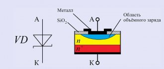
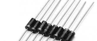
The Schottky diode differs from ordinary diodes in its design, which uses a metal-semiconductor rather than a pn junction. It is clear that the properties here are different, which means the characteristics should also be different.
Indeed, a semiconductor metal has the following parameters:
- The leakage current is of great importance,
- Low voltage drop across the junction when connected directly,
- Restores charge very quickly, as it has a low value.
The Schottky diode is made from materials such as gallium arsenide, silicon, and much less commonly, but can also be used, germanium. The choice of material depends on the properties that need to be obtained, however, in any case, the maximum reverse voltage for which these semiconductors can be manufactured is not higher than 1200 volts - these are the highest voltage rectifiers. In practice, they are much more often used at lower voltages - 3, 5, 10 volts.
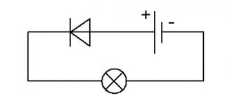
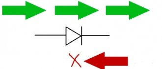
In the circuit diagram, the Schottky diode is designated as follows:
But sometimes you can see this designation:
This means a dual element: two diodes in one housing with a common anode or cathode, so the element has three terminals. Power supplies use such designs with a common cathode; they are convenient to use in rectifier circuits. Often the diagrams show the markings of a regular diode, but the description indicates that this is a Schottky diode, so you need to be careful.
Diode assemblies with a Schottky barrier are available in three types:
Type 1 – with a common cathode,
Type 2 – with a common anode,
Type 3 – according to the doubling scheme.
This connection helps to increase the reliability of the element: after all, being in the same housing, they have the same temperature regime, which is important if powerful rectifiers are needed, for example, 10 amperes.
But there are also disadvantages. The thing is that the low voltage drop (0.2–0.4 V) of such diodes appears at low voltages, usually 50–60 volts. At higher values they behave like regular diodes. But in terms of current, this circuit shows very good results, because it is often necessary - especially in power circuits and power modules - for the operating current of semiconductors to be at least 10A.
Another major disadvantage: for these devices, the reverse current cannot be exceeded even for an instant. They immediately fail, while silicon diodes, if their temperature has not been exceeded, restore their properties.
But there are still more positive things. In addition to the low voltage drop, the Schottky diode has a low junction capacitance value. As you know: lower capacity - higher frequency. Such a diode has found application in switching power supplies, rectifiers and other circuits with frequencies of several hundred kilohertz.
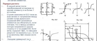
Current-voltage characteristic of the LED (volt-ampere characteristic)
The current-voltage characteristic of such a diode has an asymmetrical appearance. When a forward voltage is applied, it is clear that the current increases exponentially, and when reverse voltage is applied, the current does not depend on the voltage.
All this can be explained if you know that the operating principle of this semiconductor is based on the movement of the main carriers - electrons. For the same reason, these devices are so fast: they do not have recombination processes characteristic of devices with pn junctions. All devices with a barrier structure are characterized by asymmetry of the current-voltage characteristics, because it is the number of electric charge carriers that determines the dependence of current on voltage.
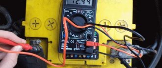
How to test a diode with a multimeter
Typically, power rectifier diodes fail because significant forward current passes through them. The cause of diode malfunctions may be their overheating, disruption of thermal contact with the radiator or an increase in ambient temperature, failure of other circuit elements that caused an increase in the permissible voltage on the diode, or poor quality of their performance.
Failure of the rectifier diodes can cause an increase in the supply voltage to the circuit components and cause additional malfunctions. Diode failure can be expressed in a short circuit between different semiconductors of the pn layer, lack of contact between them (break) and the appearance of a leakage current.
A diode is a semiconductor whose operation is based on the properties of a pn junction. The operation of the element is that in the forward direction anode (+) - cathode (-) current passes through the semiconductor junction, since its resistance is only a few tens of Ohms, and in the opposite direction cathode - anode (inverted diode) there is no current, i.e. because the transition resistance is quite high.
Using this property of pn semiconductors, it is not difficult to check the performance of the diode with a multimeter. Some multimeters have a diode test mode, which is marked with a diode symbol. When the red probe of the device touches the anode of the semiconductor, and the negative cathode with another probe, then on the screen of the measuring device, if the element is in good condition, the voltage at the junction will be displayed, in the case of germanium diodes from 0.3 to 0.7 V, and from 0.7 to 1 B for silicon semiconductors.
Diode test mode on a multimeter
The difference in the forward voltage drop of these semiconductors depends on the different junction resistances. If you turn the probes over and touch the positive anode with a black probe and the negative cathode with a red probe, the display will display a voltage drop close to zero (in the case of a working element). If the multimeter does not have such a test mode, then the functionality of the element is checked in resistance mode.
Place the multimeter switch in the resistance measurement position of 1 Kom, and then apply the red probe to the anode of the element, and the black probe to the cathode. The device screen should display the direct junction resistance value for a working diode from tens to hundreds of ohms, which depends on the type of semiconductor. If the semiconductor material is germanium, then the direct junction resistance is lower than that of silicon elements.
If the probes are turned over, then the resistance of the pn junction will be high (if the semiconductor is in good condition) from several hundred Kohm to Mohm. When the reverse junction resistance is noticeably lower, then we can talk about unacceptable leakage current and a faulty element.
Use in practice
Schottky rectifiers are used in switching power supplies, voltage stabilizers, switching rectifiers. The most demanding current - 10A or more - are voltages of 3.3 and 5 volts. It is in such secondary power circuits that Schottky devices are most often used. To amplify the current values, they are connected together in a circuit with a common anode or cathode. If each of the dual diodes is rated at 10 amperes, you will get a significant safety margin.
One of the most common malfunctions of switching power modules is the failure of these same diodes. As a rule, they either completely break through or leak. In both cases, the faulty diode must be replaced, then the power transistors must be checked with a multimeter, and the supply voltage must also be measured.
How to check an LED, Zener diode, Schottky diode with a multimeter
LEDs are tested in the same way as power diodes - for resistance. When connecting the device probes directly to the LED, the display will show a small resistance. In this case, the LED may have a dim glow. If you change the probes, the transition resistance will be high.
The Schottky diode is tested using the method of testing a conventional diode. The zener diode is also tested in different positions of the electrodes. But this is not enough to test zener diodes. The multimeter can show acceptable resistance values in both directions of the transition, and the stabilization voltage will differ from the required value.
A simple zener diode test circuit
To check the stabilization voltage, you need to assemble a simple circuit with a current-extinguishing resistance. The power supply voltage is usually taken 2 - 3 V higher than the stabilization voltage of the zener diode. As an example, let's take a D814B zener diode with a stabilization voltage of 9 V and a stabilization current of 5 mA. The limiting resistor can be approximately calculated using the formula:
R = U1-U2/I = 12 -9/0.005 = 600 Ohm.
U1 – power supply voltage,
U2 – zener diode stabilization voltage,
I – rated current of the zener diode.
Having placed such a resistance in the zener diode testing circuit, measure the stabilization voltage on the zener diode; it should be 9 V, taking into account the deviation + 0.5 - 1 V, that is, the stabilization voltage should have a value of 8 - 9.5 Volts.
Test method
Digital multimeters test diodes and zener diodes very accurately. If there is a mode designed for this, the tester will also show the breakdown voltage value. When using a dial multimeter, you can check the diode for resistance in ohmmeter mode. Before this, you should set the tester needle to zero. To do this you should:
- bridge the probes of the device;
- turn the special knob to make adjustments;
- If it is not possible to set the arrow to zero, then it is necessary to replace the probe batteries.
To check the zener diode with a multimeter, you should connect the red probe to the anode, and the black probe to the cathode. First you should measure the resistance of the part. It should be from 500 to 1 thousand ohms. Testing for breakdown voltage has its own characteristics due to the design of the zener diode. The main purpose of the latter is to maintain a constant voltage value in the circuit in parallel to which the part is connected.
For this reason, testing this semiconductor device can be difficult , since the breakdown voltage may be lower. Because of this, they sometimes make the erroneous conclusion that the zener diode is faulty.
A more accurate check can be carried out by assembling a simple circuit. It includes an adjustable current source and a limiting resistor. A zener diode is considered serviceable if the voltage at its terminals remains unchanged.
How to check a diode bridge with a multimeter
A simple diode bridge consists of four diodes assembled in a bridge circuit and is designed for primary rectification of alternating voltage. In the case of a rough check of the diode bridge, you can measure the junction resistance of individual diodes as usual. But then the leakage current cannot be checked.
To check this important parameter, you need to disconnect any semiconductor electrode from the electrical circuit. It is possible to check the presence of leakage current in individual power diodes without disconnecting them from the circuit, using the difference in temperature of the semiconductor cases. A faulty semiconductor will have a higher case temperature than healthy elements.
For this method of testing diodes for leakage current, it is important that they are free-standing and without radiators. It is not always possible to check the temperature difference by hand (with the power source turned off). Therefore, it is better to measure the temperature with a multimeter sensor that has this mode. You can roughly check the diode with a multimeter without desoldering it from the board in the usual way, and in most cases this is quite enough.
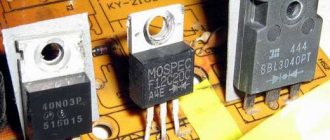
Basic Schottky diodes found in power supplies
Schottky TO-220 SBL2040CT 10A x 2 =20A 40V Vf=0.6V at 10A Schottky TO-247 S30D40 15A x 2 =30A 40V Vf=0.55V at 15A Ultrafast TO-220 SF1004G 5A x 2 =10A 200V Vf=0.97V at 5A Ultrafast TO-220 F16C20C 8A x 2 =16A 200V Vf=1.3V at 8A Ultrafast SR504 5A 40V Vf=0.57 Schottky TO-247 40CPQ060 20A x 2 =40A 60V Vf=0.49V at 20A Schottky TO-247 STPS 40L45C 20A x 2 =40A 45V Vf=0.49V Ultrafast TO-247 SBL4040PT 20A x 2 =40A 45V Vf=0.58V at 20A Schottky TO-220 63CTQ100 30A x 2 =60A 100 Vf=0.69V at 30A Schottky TO-220 MBR2545CT 15A x 2 = 30A 45V Vf=0.65V at 15A Schottky TO-247 S60D40 30A x 2 =60A 40-60V Vf=0.65V at 30A Schottky TO-247 30CPQ150 15A x 2 =30A 150V Vf=1V at 15A Schottky TO-220 MBRP3045N 15A x 2 =30A 45V Vf=0.65V at 15A Schottky TO-220 S20C60 10A x 2 =20A 30-60V Vf=0.55V at 10A Schottky TO-247 SBL3040PT 15A x 2 =30A 30-40V Vf=0.55V at 15A Schottky TO -247 SBL4040PT 20A x 2 =40A 30-40V Vf=0.58V at 20A Ultrafast TO-220 U20C20C 10A x 2 =20A 50-200V Vf=0.97V at 10A
There are also modern domestic diode assemblies for high current. Here are their markings and internal diagram:
High-voltage Schottky diodes are also produced, which can be used, for example, in power supplies for tube amplifiers and other equipment with high power supply. The list is given below:
Although it is more preferable to use Schottky diodes in low-voltage powerful rectifiers with output voltages of a couple of tens of volts at high switching frequencies.
Source: tehnoobzor.com
Classification
Diodes are simple semiconductor radioelements based on a pn junction. The figure shows a graphical representation of the most common types of these devices. Anode o, cathode - “-” (given for clarity; in the diagrams, a graphic designation is sufficient to determine the polarity).
Accepted notations
Types of diodes shown in the figure:
- A – rectifying;
- B – zener diode;
- C – varicap;
- D – microwave diode (high voltage);
- E – reversed diode;
- F – tunnel;
- G – LED;
- H – photodiode.
Now let's look at verification methods for each of the listed types.
What is a diode
A diode is an electronic type of element on a board, which consists of several semiconductor layers and has different permeability and power, depending on the direction of the electric current. The electrode is divided into an anode and a cathode. In most cases, it is needed in order to carry out protective modulations with rectification and conversion of incoming electrical signals on the suppressor.
What is a diode
Checking the rectifier diode and zener diode
The protective diode, as well as the rectifier diode (including the power diode) or Schottky diode, can be checked using a multimeter (or use an ohmmeter); to do this, we switch the device to the continuity mode as shown in the photo.
Multimeter mode in which semiconductor rectifier diodes are tested
We connect the probes of the measuring device to the terminals of the radio element. By connecting the red wire (“+”) to the anode and the black (“-”) wire to the cathode, the multimeter (or ohmmeter) display will display the threshold voltage value of the diode being tested. After we change the polarity, the device should show infinitely high resistance. In this case, we can state that the element is in good condition.
If, when connecting back, the multimeter registers a leak, it means that the radio element has “burnt out” and needs to be replaced.
Note that this testing technique can be used to test diodes on a car generator.
Zener diode testing is carried out according to a similar principle, however, such a test does not allow one to determine whether the voltage is stabilized at a given level. Therefore, we need to assemble a simple circuit.
Testing using a regulated power supply
Designations:
- PSU – adjustable power supply (displaying load current and voltage);
- R – current-limiting resistance;
- VT – Zener diode or avalanche diode under test.
The verification principle is as follows:
- we assemble the circuit;
- set the multimeter mode, which allows you to measure DC voltage up to 200 V;
Selecting the required mode for testing
- turn on the power supply and begin to gradually increase the voltage until the ammeter on the power supply shows that current is flowing through the circuit;
- connect the multimeter as shown in the figure and measure the stabilization voltage.
Output rectifiers
Previous articles in the series “Circuit design of power supplies for personal computers”:
Here we will talk about output rectifiers for personal computer power supplies.
AT form factor power supplies use four secondary voltages: +5V , -5V , +12V , -12V, designed for different load currents. Rectifiers are made only in full-wave circuits with a midpoint, and “bridge” circuits, as a rule, are not used due to large losses. You can read about the types of AC rectifiers here.
The use of a full-wave rectification circuit has led to the use of dual diodes with a common cathode in +5V and +12V rectifiers.
A dual diode is two semiconductor diodes housed in one common package. One of the three terminals of such a diode is common. The terminals of cathodes, anodes, as well as the anode of one diode and the cathode of another can be combined.
-5V and -12V rectifiers typically use separate, discrete, low-power diodes since the consumption on the -5V and -12V power rail is low. In exceptional cases, low-power dual diodes with a common anode can be used. In practice, this is rare.
Here is a photo showing the rectifier diodes, which are removed from the printed circuit board along with the radiator. As you can see, the diodes are attached to the radiator through an insulating gasket.
The “healthiest” dual diode located in the center ( SBL3040PT ) is used in the +5V rectifier. The SBL3040PT diode is a dual Schottky diode. It is designed for forward current up to 15 amperes (one diode) and reverse voltage up to 40 volts.
F12C20C is installed nearby . It is used in a +12V rectifier. This diode can withstand forward current up to 6 amperes (one diode) and reverse voltage up to 200 volts. Unlike the SBL3040PT, the F12C20C diode is a regular (non-Schottky) high-speed common-cathode rectifier diode.
40N03P MOSFET field-effect transistor . Externally, it is very similar to a dual diode. This transistor is used in ATX format switching power supplies.
The main feature of all secondary sources in switching power supplies is smoothing filters, which start with chokes, and only then come capacitors.
Only in filters starting with a choke, the output voltage depends on both the amplitude and duty cycle of the pulses arriving at the input. Therefore, by changing the duty cycle it is easy to regulate the output voltage.
Duty factor is an extra-system unit expressing the ratio of the pulse duration to the repetition period. The process of changing the duty cycle is called PWM - pulse width modulation. (English: PWM – P ulse W idth Modulation ).
Next, let's look at the diagram. The figure shows a diagram of the output rectifiers of the PC type pulse unit. Transformer T2 is a high-frequency step-down power transformer, which was already discussed in the second part. It has several secondary windings from which the reduced alternating voltage is removed.
In the diagram you can see that in the circuits of all rectifiers there is a choke with the designation L1. 1 , L1. 2 , L1. 3 , L1. 4 . If you look at the diagram, you might think that these are separate chokes. But in fact, these are four chokes wound on one common ring magnetic core. The windings of the inductors are not electrically connected, but they have a common magnetic field. And this is not without reason.
Due to this technique, the so-called group stabilization of output voltages is ensured. Due to the general magnetic field in inductor L1, it is possible to stabilize all output voltages at once. If you remove inductor L1 from the circuit and measure the output voltages, you can make sure that they begin to “walk” noticeably. This is what inductor L1 looks like with a common ring magnetic core on a printed circuit board.
Next in the filters are electrolytic capacitors C4 - C8 with a capacity of 330 μF to 2200 μF. The operating voltage of electrolytes, as a rule, depends on which of the rectifiers the capacitor is installed in (at +5V and -5V - at 10.16 volts, and at +12V and -12V - at 16.25 volts). Resistors R4 - R7 create a small initial load for the correct operation of the rectifier with an inductive filter. They also serve to discharge electrolytic capacitors after turning off the switching power supply.
As already noted, Schottky diodes are often used as secondary source diodes. They have a low voltage drop in the forward direction and a fast recovery time, but the low reverse voltage does not allow the positive qualities of these diodes to be fully used. Since the circuits of secondary power supplies are not complicated, repairs come down to replacing electrolytic capacitors and rectifier diodes.
There are certain difficulties associated with diagnosing Schottky diodes. They have a very bad phenomenon called “leakage”. If you check the diode, it will turn out to be serviceable, but after some time of normal operation, due to heating, it begins to “float”. If you have the slightest suspicion about the serviceability of such a diode, you should not waste time, but it makes sense to simply replace it with a known good one.
Varicap testing
Unlike conventional diodes, the pn junction of varicaps has a variable capacitance, the value of which is proportional to the reverse voltage. Checking for open or short circuits for these elements is carried out in the same way as for conventional diodes. To check the capacity, you will need a multimeter that has a similar function.
Demonstration of checking varicap
To test, you will need to set the multimeter to the appropriate mode, as shown in photo (A) and insert the part into the connector for capacitors.
As one of the commentators on this article correctly noted, it is indeed impossible to determine the capacitance of a varicap without using the rated voltage. Therefore, if there is a problem with identification by appearance, you will need to assemble a simple attachment for a multimeter (I repeat for critics, a digital multimeter with the function of measuring the capacitance of capacitors, for example UT151B).
Multimeter attachment for measuring varicap capacity
Designations:
- Resistors: R1, R2 -120 kOhm (yes, two resistors, yes in series, no, one cannot be replaced, parasitic capacitance, no further comment); R3 – 47 kOhm; R4 – 100 Ohm.
- Capacitors: C1 – 0.15 µF; C2 – 75 pF; C3 – 6…30 pF; C4 - 47 uF ha 50 volts.
The device requires configuration. It is quite simple, the assembled device is connected to a measuring device (a multimeter with a capacitance measurement function). Power must be supplied from a stabilized power source (important) with a voltage of 9 volts (for example, a Krona battery). By changing the capacitance of the substring capacitor (C2), we achieve a reading on the indicator of 100 pF. We will subtract this value from the device reading.
Schottky diode assemblies in computer power supplies
During the assembly of power supplies and voltage converters for car amplifiers, a problem often arises with rectifying the current from the transformer. Getting hold of powerful pulsed diodes is quite a serious problem, so I decided to publish an article that provides a complete list and parameters of powerful Schottky diodes. Some time ago, I personally had a problem with the converter rectifier for a car amplifier. The converter is quite powerful (500-600 watts), the output voltage frequency is 60 kHz, any common diode that can be found in old trash will immediately burn out like a match. The only available option at that time was the domestic KD213A. The diodes are quite good, they hold up to 10 Amps, the operating frequency is within 100 kHz, but they also overheated terribly under load.
In fact, powerful diodes can be found in almost everyone. A computer power supply is a switching power supply that powers the entire computer. As a rule, they are made with a power from 200 watts to 1 kW or more, and since the computer is powered by direct current, this means that the power supply must have a rectifier. Modern power supplies use powerful Schottky diode assemblies to rectify the voltage - they have a minimal voltage drop across the transition and the ability to work in pulsed circuits, where the operating frequency is much higher than the network 50 Hz. Recently they brought several power supplies for free, from where the diodes were removed for this short review. In computer power supplies you can find a variety of diode assemblies; there are almost no single diodes here - in one case there are two powerful diodes, often (almost always) with a common cathode. Here are some of them:
D83-004 (ESAD83-004)
— A powerful assembly of Schottky diodes, reverse voltage 40 Volts, permissible current 30A, in pulse mode up to 250A - perhaps one of the most powerful diodes that can be found in computer power supplies.
STPS3045CW
— Dual Schottky diode, rectified current 15A, forward voltage 570 mV, reverse leakage current 200 μA, reverse voltage constant 45 Volts.
Checking the suppressor (TVS diode)
Protective diode, also known as limiting zener diode, suppressor and TVS diode. These elements come in two types: symmetrical and asymmetrical. The former are used in alternating current circuits, the latter - in direct current. If we briefly explain the principle of operation of such a diode, it is as follows:
An increase in input voltage causes a decrease in internal resistance. As a result, the current in the circuit increases, which causes the fuse to trip. The advantage of the device is its fast response, which allows it to absorb excess voltage and protect the device. Response speed is the main advantage of a protective (TVS) diode.
Now about the verification. It is no different from a regular diode. True, there is an exception - Zener diodes, which can also be attributed to the TVS family, but in essence they are a fast zener diode operating according to the “mechanism” of avalanche breakdown (Zener effect). But the performance check reverts to a regular dialing test. Creating triggering conditions leads to failure of the element. In other words, there is no way to check the protective functions of a TVS diode; it’s like checking a match (whether it’s good or not) by trying to light it.
Operating principle
The operating principle of a Schottky diode is almost no different from semiconductor diodes. A special feature is the presence of metal. A typical semiconductor uses two substances that form electrons with a positive and a negative charge inside them. When an electric current passes, part of the charge is lost to the formation of these electrons.
A Schottky diode uses a metal and a semiconductor. Gold, silicon, and germanium are used as metal barriers in production. A diode also consists of an anode and a cathode. When voltage is applied to the anode, the metal creates a magnetic barrier to the direct passage of voltage. Electrons with a negative charge are created on its surface. When a significant magnetic field is formed, the element is pulsedly discharged. Such a discharge can be repeated an infinite number of times, subject to the operating voltage and temperature.
The most comfortable voltage for this type of diode is 40–60 volts. It is this voltage that allows the transition to be made without losing a fraction of the voltage and without increasing the temperature.
Temperature also plays a significant role in the rapid transfer of charges. When the input voltage is low, a temperature rise is created. Due to this, the number of charged electrons increases, which quickly overcome the metal barrier.
High Voltage Diode Testing
It will not be possible to check the high-voltage diode of a microwave oven in the same way as a regular one, due to its features. To test this element, you will need to assemble a circuit (shown in the figure below) connected to a 40-45 volt power supply.
Circuit for testing a diode used in a microwave oven
A voltage of 40-45 volts will be enough to test most elements of this type; the testing methodology is the same as for conventional diodes. The resistance value R should be in the range from 2 kOhm to 3.6 kOhm.
Diode check
Important . For the procedure, the oven must be disconnected from the power supply. The cord is removed from the outlet.
Then perform a visual inspection of the microwave. If there are no melted areas or darkened areas, it is necessary to use a special measuring device.
How to find a high voltage diode
The mechanism works according to one principle. But there are many varieties of this element. The design of the microwave oven has a circuit board with markings. The required element is usually indicated by the symbol DB 1.
As soon as you figure out which model your microwave belongs to, you can replace the part with a similar element. The markings will be different, but the type of operation of the product will be the same. It’s just that each manufacturer has its own labeling system.
The technical characteristics of the part are as follows:
- current output up to 700 mA;
- the highest voltage is about 5 kV.
How to test a high voltage diode with a multimeter
To assess the condition of an important part, you need to use a special device - a multimeter.
After disconnecting the heating equipment from the power supply and removing the oven element, you need to turn the part over. This will allow you to measure the voltage on both sides.
Resistance is measured in both forward and reverse directions.
- The multimeter must be set to R x 1000 mode.
- Connect it to the diode, to the terminal with the + sign (this is direct resistance). The tester should show the final resistance on the screen.
- After this, connect to the terminal with a minus sign. This is a measurement of the reverse direction of resistance. The tester should display infinity.
Important . The multimeter must be connected to a network of at least 9 volts.
Testing a high-voltage capacitor with a multimeter is only possible for breakdown. If the device shows a short circuit, the part must be replaced.
Tunnel and reverse diodes
Considering that the current flowing through a diode depends on the voltage applied to it, testing consists of analyzing this dependence. To do this, you will need to assemble a circuit, for example, such as shown in the figure.
Testing tunnel type diodes
List of elements:
- VD – tunnel type diode under test;
- Up – any galvanic power source with a discharge current of about 50 mA;
- Resistances: R1 – 12Ω, R2 – 22Ω, R3 – 600Ω.
The measurement range set on the multimeter should not be less than the maximum current of the diode; this parameter is indicated in the datasheet of the radio element.
Video: Example of checking a diode with a multimeter
Testing algorithm:
- the maximum value is set on variable resistor R3;
- the element under test is connected, observing the polarity indicated on the diagram;
- By decreasing the value of R3, we observe the readings of the measuring device.
If the element is working properly, during the measurement process the device will show an increase in current up to Imax of the diode, followed by a sharp decrease in this value. With a further increase in voltage, the current will decrease to Imin, after which it will begin to increase again.
Analysis of results
By checking, you can judge whether the semiconductor is working or not. A sign of whether the electrode is operational or not will be the matching values that are displayed on the instrument panel in the order when the anode is connected to the electrode with a minus value, and the cathode to the one with a plus value.
As for the opposite connection order, a good result would be 0. When evaluating the results, it is important to take into account the voltage level. It can sometimes depend on the type of electrode.
The result is zero
If you follow these parameters, you can understand what state the diode is in. Whether there is a breakdown or not. If any indicator is unsatisfactory, then the semiconductor must be urgently replaced.
Interestingly, anyone can check the diodes. Today, there are a large number of budget multimeters on the market that can accurately show the true results of testing the performance of a diode on any household electrical appliance.
You may be interested in: Types of household and industrial electrical switches
Bad result of the measuring device
A diode is an electronic element that has a certain current conductivity. You can check it using a tester or multimeter. This must be done according to the instructions that come with any testing device.
LED testing
Testing LEDs is practically no different from testing rectifier diodes. How to do this was described above. We check the LED strip (more precisely, its SMD elements), infrared LED, and also laser LED using the same method.
Unfortunately, a powerful radio element of this group, which has a higher operating voltage, cannot be tested using the indicated method. In this case, you will additionally need a stabilized power source. The testing algorithm is as follows:
- We assemble the circuit as shown in the figure. The power supplies are set to the operating voltage of the LED (indicated in the datasheet). The measuring range on the multimeter should be up to 10 A. Note that you can use the charger as a power supply, but then you need to add a current-limiting resistor;
Measuring the rated current on an LED
- measure the rated current and turn off the power supply;
- set the multimeter mode, which allows you to measure DC voltage up to 20 V, and connect the device in parallel to the element under test;
- turn on the power supply and remove the operating voltage parameters;
- We compare the data obtained with those indicated in the datasheet, and based on this analysis we determine the performance of the LED.
PhiX › Blog › REPAIR OF COMPUTER POWER SUPPLY SUPPLY
In this article, I will talk a little about the basics of repairing computer, switching power supplies of the ATX standard. This is one of my first articles, I wrote it about 5 years ago, so I ask you not to judge strictly.
Precautionary measures.
Repairing switching power supplies is a rather dangerous task, especially if the fault concerns the hot part of the power supply. Therefore, we do everything thoughtfully and carefully, without haste, in compliance with safety precautions.
Power capacitors can hold a charge for a long time, so do not touch them with bare hands immediately after turning off the power. Under no circumstances should you touch the board or heatsinks while the power supply is connected to the network.
In order to avoid fireworks and preserve still living elements, you should solder a 100-watt light bulb instead of a fuse. If, when the power supply is turned on, the lamp flashes and goes out, everything is fine, but if, when turned on, the lamp lights up and does not go out, there is a short circuit somewhere.
The power supply should be checked after repairs are made away from flammable materials.
Soldering iron, solder, flux. A soldering station with power adjustment or a pair of soldering irons of different power is recommended. A powerful soldering iron is needed for soldering transistors and diode assemblies that are located on radiators, as well as transformers and chokes. Various small things are soldered with a soldering iron of lower power. Solder suction and/or braiding. Serve to remove solder. Screwdriver Side cutters. Used to remove plastic clamps that hold wires together. Multimeter Tweezers 100W light bulb Purified gasoline or alcohol. Used to clean the board from traces of soldering. BP device.
A little about what we will see when we open the power supply.
Internal image of an ATX system power supply
A – diode bridge, used to convert alternating current to direct current
B – power capacitors, used to smooth the input voltage
Between B and C there is a radiator on which the power switches are located
C – pulse transformer, serves to generate the required voltage ratings, as well as for galvanic isolation
between C and D – radiator on which rectifier diodes of output voltages are located
D – group stabilization choke (GS), used to smooth out noise at the output
E – output, filtering, capacitors, used to smooth out noise at the output
Pinout of the 24 pin connector and voltage measurement.
We will need knowledge of the contacts on the ATX connector to diagnose the power supply. Before starting repairs, you should check the voltage of the standby power supply; in the figure, this contact is marked in blue + 5V SB, usually this is a purple wire. If the duty station is in order, then you should check the presence of the POWER GOOD signal (+5V), in the figure this contact is marked in gray, PW-OK. Power good appears only after the power supply is turned on. To start the power supply, we close the green and black wires, as in the picture. If PG is present, then most likely the power supply has already started and the remaining voltages should be checked. Please note that output voltages will vary depending on the load. So, if you see 13 volts on the yellow wire, do not worry, it is likely that under load they will stabilize to the standard 12 volts.
If you have a problem in the hot part and need to measure voltages there, then all measurements must be carried out from the common ground, this is the minus of the diode bridge or power capacitors.
The first thing to do is open the power supply and perform a visual inspection.
If the power supply is dusty, clean it. We check whether the fan is spinning; if it is, then this is most likely the reason for the failure of the power supply. In this case, you should look at diode assemblies and DGS. They are most prone to failure due to overheating.
Next, we inspect the power supply unit for burnt elements, PCB darkened by temperature, swollen capacitors, charred DGS insulation, broken tracks and wires.
Before opening the power supply, you can try to turn on the power supply to be sure of the diagnosis. A correct diagnosis is half the treatment.
The power supply does not start, there is no standby voltage. The power supply does not start, but the standby voltage is present. No PG signal. The power supply goes into defense, the power supply works, but it stinks. The output voltages are too high or low . Fuse.
Source: www.drive2.ru
Checking the photodiode
In a simple test, the reverse and forward resistance of a radio element placed under a light source is measured, after which it is darkened and the procedure is repeated. For more accurate testing, you will need to take the current-voltage characteristic; this can be done using a simple circuit.
An example of a circuit for measuring current-voltage characteristics
To illuminate the photodiode during testing, you can use an incandescent lamp with a power of 60 W or more as a light source or bring the radio component to a chandelier.
Photodiodes sometimes have a characteristic defect, which manifests itself in the form of a chaotic change in current. To detect such a malfunction, it is necessary to connect the element under test as shown in the figure and measure the reverse current for a couple of minutes.
Testing for "creep"
If during testing the current level remains unchanged, then the photodiode can be considered working.
Testing without desoldering.
As practice shows, it is not always possible to test a diode without desoldering it when it is on the board, like other radio components (for example, a transistor, capacitor, thyristor, etc.). This is due to the fact that elements in the circuit may produce an error. Therefore, before checking the diode, it must be desoldered.
Examination
Next, we will describe in detail how to test a Schottky diode using a digital multimeter. These radio components can be tested using the methods described below and with analog measuring instruments.
Before testing the described radio component, you need to know the following nuances:
- Each single diode is marked with a white or gray ring. This indicates the cathode of the device. A negative charge flows through this leg or it is a shut-off input.
- When making a call, it is worth knowing that diodes show their performance only from the open input side.
- The elements being tested and measuring probes must not be held in your hands. The tester will show human resistance, which can lead to errors in measurements.
- It is also worth knowing what voltage comes from the tester when taking measurements in continuity and resistance mode. This is necessary to compare the result with the characteristics of the part being tested. For example, the tester produces 9 volts for continuity, the diode voltage drop is 5 volts. This means that when measuring, the element should produce data within 4–4.5 volts.
- You cannot test a device connected through the AC phase.
So, now you can start checking.
One diode
Testing a single element begins by turning the multimeter into resistance measurement mode. Next you need:
- Connect the black measuring probe to the side marked with the ring, that is, to the cathode.
- The red test lead is connected to the anode.
- The tester should show transition resistance. If “0” or “1” is displayed in this position, then the element can be considered faulty.
- Next, reverse conductivity is checked. To do this, you need to change the position of the measuring probes. There should be no resistance when changing polarity. If there are even minor readings, then the device is faulty.
The device is checked in exactly the same way in dialing mode. If the polarity is correct, the tester should produce a result with a difference of 300 mV. There should be no result when changing the polarity.
Checking in the “PNP/NPN” socket
Modern multimeters are equipped with a special connector for checking the integrity of transistors. This connector can be used for Schottky diode testing. To do this you need:
- Set the multimeter to “hFE” mode.
- Insert the anode into hole “P”.
- Cathode into hole "N".
- The tester will show the conductivity of the element. Next you will need to change the polarity. Just turn the diode over and put it back in. Lack of conductivity will indicate the integrity of the device.
These tests will accurately indicate the current loss rate at the output, as well as the overall performance of the part.
Checking double elements
Such parts are made in one housing similar to a transistor. They have one anode and 2 cathodes or vice versa. Before checking, you need to make sure which part is in front of you. For example, it is necessary to test a cell with one anode in the center and two cathodes at the edges. Next you need:
- The tester is switched to dialing mode.
- The red measuring probe is connected to the central leg of the part.
- The black test lead is connected to the "1" cathode.
- The tester should produce an audible signal and the measurement result minus the loss of up to 300 mV.
- Leg “2” is tested in the same way. The result should be similar.
- If the element passes the test with this position of the test probes, then it is necessary to change the polarity and repeat the test.
The same check will show the integrity of the elements of a dual assembly consisting of 4 diodes.
Diode bridge
Schottky diodes are actively used as components of diode bridges for various types of power supplies and rectifiers. The diode bridge consists of 4 parts that are connected in series to each other. This circuit has 2 pins for AC input and 2 pins for DC output. Using a digital tester, you can easily check the integrity of this device.
This is done as follows:
- Before testing, the power supply must be de-energized.
- Allow the capacitors to discharge.
- Switch the multimeter to dialing mode.
- The red measuring probe is connected to pin “1” of the input.
- The black measuring probe is connected to pin “2” of the input.
- The absence of a buzzer indicates that the diodes at the input are working.
Next, each pair is checked separately.
- The red measuring probe is connected to the “-” contact.
- Black test lead with any AC input "~" pin.
- The tester should produce a value within 500 mV. This pair is working.
- The second input contact is checked in the same way. The data must also be within 500 mV.
Next you need to repeat the test, but change the position of the probes. Connect the black measuring probe to “-”, and check the input contacts with the red one. The tester should not output any values or only “1”. This indicates that the junction inside the diodes is closed on that side. If there is data, the bridge is not suitable for inclusion in the network.
Next, the DC voltage output is checked. To do this you need:
- Connect the black measuring probe to the “+” contact.
- Using a red test lead, take measurements on the AC input contacts.
- The result should be within 500 mV.
- When changing the polarity and re-checking, there should be no result or it will be equal to “1”.
This check will indicate the integrity of the device. If a faulty diode is detected in the diode bridge, then they must be replaced with exact analogues. After their installation has been completed, it is necessary to re-check the integrity of the bridge, and only then check it with an alternating voltage connection.
Check on board
You can test the Schottky diode on the board. But for this it is better to desolder the cathode of the element. This completely eliminates the problem of erroneous measurements of the resistance of radio components mounted nearby.
How to check LED strip for performance
On our website there is a whole article on how to check an LED strip; here we will look at express testing methods.
I’ll say right away that it won’t be possible to illuminate it entirely with a multimeter; in some situations, only a slight glow is possible in Hfe mode. Firstly, you can check each diode individually, in the diode test mode.
Secondly, sometimes it is not the diodes that burn out, but the current-carrying parts. To check this, you need to put the tester into continuity mode and touch each power terminal at different ends of the area being tested. This way you will identify the intact part of the tape and the damaged one.
The red and blue lines highlight the stripes that should ring from the very beginning to the end of the LED strip.
How to test an LED strip with a battery? The power supply for the tape is 12 Volts. You can use a car battery, but it is large and not always available. Therefore, a 12V battery will come to the rescue. Used in radio doorbells and control panels. It can be used as a power source when testing problematic areas of the LED strip.
Schottky diode: operating principle
The Schottky valve differs from the classic type in that the basis of its operation is a semiconductor-metal pair. This pair is often referred to as the Schottky barrier. This barrier, in addition to its ability to conduct electricity in one direction, similar to a pn junction, has several useful features.
Gallium arsenide and silicon are the main suppliers of material for the production of electronic elements in industrial settings. In more rare cases, precious chemical elements are used: platinum, palladium and the like.
Its graphical conditional expression on electrical circuits does not coincide with classical diodes. The markings of electronic components are similar. There are also double diodes in the form of an assembly.
Important! A double diode is a pair of diodes combined in a common volume.
Dual Schottky barrier diode
For dual valves, the outputs of the cathodes or anodes are combined. It follows that such a product has three ends. Common cathode assemblies, for example, work where switching power supplies are required. Schottky diodes with a common anode are used much less frequently.
The diodes are located in a single housing and use the same production technology for their manufacture, so in terms of their set of parameters they are like twin brothers. Their operating temperature is also the same, because... are in a common space. This property significantly reduces the need to replace them due to loss of performance.
The most important distinguishing properties of the valves under consideration are a slight forward voltage drop (up to 0.4 V) at the moment of transition and a high response time.
However, the mentioned voltage drop has a narrow range of applied voltage - no more than 60 V. And this value itself is small, which sets a rather narrow range of applications for these diodes. If the voltage exceeds the specified value, the barrier effect disappears and the diode begins to operate in the mode of a conventional rectifier diode. The reverse voltage for most of them does not go beyond 250 V, however, there are samples with a reverse voltage of 1.2 kV.
When designing electrical circuits, designers often do not highlight the Schottky diode graphically on circuit diagrams, but in the specifications for the order they indicate its use, specifying it in the type. Therefore, when ordering equipment, you need to pay close attention to this.
Among the inconveniences in working with valves with a Schottky barrier, it is necessary to note their extreme “tenderness” and intolerance to the slightest, even very short-term, excess of the reverse voltage rating. In this case, they simply fail and are no longer restored, which, in comparison with silicon diodes, is not to their benefit, because the latter have the property of self-healing, after which they can continue to work as usual without requiring replacement. We also must not forget that the reverse current in them critically depends on the degree of transition. If a significant reverse current appears, breakdown cannot be avoided.
An increased operating frequency due to low transient capacitance and a short recovery period due to high performance are positive properties that allow these diodes to be used, for example, by radio amateurs. They are also used at frequencies reaching several hundred kHz, for example, in pulsed rectifiers. A large number of produced diodes are used in microelectronics. The current level of development of science and industry allows the use of nanotechnology in the manufacturing process of valves with a Schottky barrier. The valves created in this way are used to shunt transistors. This solution significantly increases the response of the latter.
Schottky diodes in power supplies
Schottky valves are often located in computer power supplies. Five-volt voltage provides a serious current of tens of amperes, which is a record for low-voltage power systems. Schottky valves are used for these power supplies. Basically, dual diodes with a single cathode are used. Not a single high-quality modern computer power supply unit can do without such an assembly.
Diagnosis. A “burnt out” power supply unit of an electronic device most often means the need to replace the burnt-out Schottky assembly. There are only two reasons for the malfunction: increased leakage current and electrical breakdown. When the described conditions occur, electrical power to the computer stops being supplied. The defense mechanisms worked. Let's look at how this happens.
There is no voltage at the computer input on a constant basis. The power supply is completely blocked by the protection built into the computer.
There is an “incomprehensible” situation: the cooling fan starts working, then again the characteristic noise disappears. This means that the voltage at the computer input (output of the power supply) appears and disappears. Those. The protection handles periodic errors, but is in no hurry to completely block the source. Do you have an unpleasant odor coming from a hot block? The diode block definitely needs replacing. Another method of home diagnostics: when the CPU load was heavy, the power supply turned off by itself. This is a sign of a leak.
After repairing the power supply associated with replacing dual Schottky diodes, it is necessary to “ring” the transistors. In the reverse procedure, diodes also require checking. This rule is especially relevant if the cause of the repair is a leak.
Determining the characteristics of diodes
Build a simple circuit to measure the characteristics of an LED. It is so simple that you can do it without using a soldering iron.
Let's first look at how to find out how many volts our LED is with a multimeter using such a probe. To do this, carefully follow the instructions:
- Assemble the diagram. At the open circuit (in the diagram “mA”), set the multimeter in current measurement mode.
- Move the potentiometer to the maximum resistance position. Smoothly reduce it, watch the diode glow and the current increase.
- Find out the rated current : as soon as the increase in brightness stops, pay attention to the ammeter readings. Typically this is about 20mA for 3, 5 and 10 mm LEDs. After the diode reaches its rated current, the brightness of the glow remains almost unchanged.
- Find out the LED voltage: connect a voltmeter to the LED terminals. If you have one measuring device, then exclude the ammeter from it and connect the tester to the circuit in voltage measurement mode in parallel with the diode.
- Connect power, take voltage readings (see connection “V” in the diagram). Now you know how many volts your LED is.
- How to find out the power of an LED with a multimeter using this circuit? You have already taken all the readings to determine the power, you just need to multiply the milliamps by the Volts and you will get the power expressed in milliwatts.
Read also: Homemade snowmobile from a snow scooter
However, it is extremely difficult to determine the change in brightness by eye and bring the LED to the nominal mode; you need to have a lot of experience. Let's simplify the process.
Tables to help
To reduce the likelihood of burning a diode, determine by its appearance which type of LED it is similar to. There are reference books and comparison tables for this; rely on the reference rated current when carrying out the characterization process.
If you see that at the nominal value it clearly does not produce the full luminous flux, try to briefly exceed the current and see if the brightness continues to increase as quickly as the current. Monitor the heating of the LED. If you supply too much power, the diode will begin to heat up intensely. Conventionally, a normal temperature will be at which you cannot hold your hand on the diode, but if you touch it it will not leave a burn (70-75°C).
To understand the causes and consequences of performing this procedure, read the article on the diode’s current-voltage characteristics.
After all the work done, check yourself again - compare the readings of the devices with the table values of the LEDs, select the closest suitable parameters and adjust the circuit resistance. This way you are guaranteed to determine the voltage, current and power of the LED.
A 9V crown battery or a 12V battery is suitable to power the circuit; in addition, you will determine the total resistance for connecting the LED to such a power source - measure the resistance of the resistor and potentiometer in this position.
Checking a diode is very simple, but in practice there are different situations, so many questions arise, especially for beginners. An experienced electronics engineer will determine the parameters of most LEDs by their appearance, and in some cases, their serviceability.
How to check a diode and LED with a multimeter? It turns out that everything is very simple. This is exactly what we will talk about in our article.
How to test a diode with a multimeter
In the photo below we have a simple diode and LED.
We take our multimeter and put the knob on the diode test icon. I talked more about this and other icons in the article on how to measure current and voltage with a multimeter
I would like to add a few words about the diode. A diode, like a resistor, has two ends. And they are called cathode and anode . If you apply a plus to the anode and a minus to the cathode, then an electric current will calmly flow through the diode, but if you apply a plus to the cathode and a minus to the anode, the current will NOT flow. This is the operating principle of the PN junction on which all diodes operate.
Let's check the first diode. We place one multimeter probe on one end of the diode, the other probe on the other end of the diode.
As we can see, the multimeter showed a voltage of 436 millivolts. This means that the end of the diode that touches the red probe is the anode, and the other end is the cathode. 436 millivolts is the voltage drop across the forward junction of the diode. According to my observations, this voltage can be from 400 to 700 millivolts for silicon diodes, and for germanium diodes from 200 to 400 millivolts.
Next, swap the diode leads
A one on the multimeter means that no current is flowing through the diode. Therefore, our diode is fully functional.
How to test an LED with a multimeter
How to check the LED? Yes, exactly the same as a diode! The whole point is that if we place the red probe on the anode and the black probe on the cathode of the LED, it will glow!
Look, it glows a little! This means that the LED terminal with a red probe is the anode, and the terminal with a black probe is the cathode. The multimeter showed a voltage drop of 1130 millivolts. This is considered normal for LEDs. It can also vary depending on the “model” of the LED.
We swap the probes. The LED did not light up.
We give our verdict - a fully functional LED!
How to check diode assemblies and diode bridges? Diode assemblies and diode bridges are a connection of several diodes, usually 4 or 6. We find a circuit diagram of a diode assembly or bridge and check each diode individually. How to check the zener diode, read this article.
Designation, application and parameters of Schottky diodes
As already mentioned, the forward voltage drop of diodes with a Schottky barrier is very small. This ensures the minimum intrinsic capacitance of the Schottky diode, which makes it possible to use it more efficiently in devices with high and ultrafrequencies. Perhaps the problem is related specifically to the diodes, and anyone can disassemble the processor and see what happened inside.
An electric field will arise between the metal and the semiconductor, braking and returning the main charge carriers of the semiconductor. For example, if the anode is common, then it will be one leg out of three. The use of Schottky diodes in bridges is due to the low voltage drop across the diode, which entails lower losses on the bridge and reduces its heating.
Inspect for mechanical damage and the presence of traces of destructive chemical reactions. If a break occurs in a semiconductor or diode bridge, then it will stop passing current altogether.
The manufacturing technology of these electronic elements is very simple, which is why it is the cheapest. And the type of element used is indicated in the specification. Due to the manufacturing technology and based on the described principle of operation, Schottky diodes have a low voltage drop in the forward direction, significantly less than traditional pn-diodes. With identical parameters of the elements assembled in this way, the reliability of the entire device is ensured, primarily due to a uniform temperature. Series connection of diodes
Diode diode discord
A standard diode is a component of the electrical network and acts as a pn junction semiconductor. Its structure allows current to pass through the circuit in only one direction - from the anode to the cathode (different ends of the part). To do this, you need to apply “+” to the anode and “-” to the cathode.
Note! Electric current in diodes cannot flow in the opposite direction, from the cathode to the anode.
Due to this feature of the product, if you suspect a breakdown, it can be checked with a tester or multimeter. Today there are several types of diodes in radio electronics:
- Light-emitting diode. When an electric current passes through such an element, it begins to glow as a result of the transformation of energy into a visible glow;
- protective or regular diode. Such elements in the electrical network act as a suppressor or voltage limiter. One of the varieties of this element is the Schottky diode. It is also called a Schottky barrier diode. Such an element, when connected directly, gives a low voltage drop. In Schottky, instead of a pn junction, a metal-semiconductor junction is used.
If ordinary parts and LEDs are used in the vast majority of electrical appliances, then Schottky ones are used mainly in high-quality power supplies (for example, for devices such as computers). It is worth noting that testing a conventional diode and a Schottky diode is practically no different, since it is carried out according to the same principle. Therefore, there is no need to worry about this issue, because the operating principle of both Schottky and conventional diodes is identical. Note! Here it is only worth noting that Schottkis in most cases are found double, located in a common building. Moreover, they have a common cathode. In such a situation, you can not solder these parts, but check them “on the spot”.
Being a component of an electronic circuit, such semiconductor elements often fail. The most common reasons for their failure are:
- exceeding the maximum permissible direct current level;
- excess reverse voltage;
- poor quality part;
- violation of the device operating rules established by the manufacturer.
Moreover, regardless of the cause of loss of performance, failure can be directly caused by either a “breakdown” or a short circuit. In any case, if there is an assumption that the electrical network has failed in the semiconductor area, it is necessary to diagnose it using a special device - a multimeter. Only to carry out such manipulations you need to know how to check the diode using it correctly.
Testing and interchangeability
Schottky rectifiers can be tested in the same way as conventional semiconductors, since they have similar characteristics. You need to ring it in both directions with a multimeter - it should show itself in the same way as a regular diode: anode-cathode, and there should be no leaks. If it shows even a slight resistance - 2-10 kilo-ohms, this is already a reason for suspicion.
Read also: Wood carving attachments for engravers
Checking a Schottky diode with a multimeter
A diode with a common anode or cathode can be tested like two ordinary semiconductors connected together. For example, if the anode is common, then it will be one leg out of three. We place one tester probe on the anode, the other legs are different diodes, and another probe is placed on them.
Can it be replaced with another type? In some cases, Schottky diodes are replaced with ordinary germanium diodes. For example, D305 at a current of 10 amperes gave a drop of only 0.3 volts, and at currents of 2–3 amperes they can generally be installed without radiators. But the main purpose of the Schottky installation is not a small drop, but a low capacity, so replacement will not always be possible.
As we see, electronics does not stand still, and further applications of high-speed devices will only increase, making it possible to develop new, more complex systems.
Continuity of individual LEDs
Let's start with a simple one, how to ring an LED with a multimeter. Switch the tester to transistor testing mode - Hfe and insert the LED into the connector, as in the picture below.
How to check the LED's functionality? Insert the anode of the LED into connector C of the area marked PNP, and the cathode into E. In PNP connectors, C is the positive terminal, and E in NPN is the negative terminal. Do you see the glow? This means the LED has been checked; if not, the polarity is wrong or the diode is faulty.
The connector for testing transistors looks different, often it is a blue circle with holes, this will be the case if you check the LED with a DT830 multimeter, as in the photo below.
Now let's talk about how to test an LED with a multimeter in diode testing mode. First, take a look at the test diagram.
The diode test mode is indicated by a graphic image of a diode; more details about the designations are in the article. This method is suitable not only for LEDs with legs, but also for checking an SMD LED.
Checking LEDs with a tester in continuity mode is shown in the figure below, and you can also see one of the types of connectors for testing transistors, described in the previous method. Write in the comments about what kind of tester you have and ask questions!
This method is worse; the tester produces a bright glow from the diode, and in this case, a barely noticeable red glow.
Now pay attention to how to check the LED with a tester with an anode detection function. The principle is the same; if the polarity is correct, the LED will light up.
How is the check carried out?
After we have figured out the semiconductors of the electrical circuit and the purpose of the device, we can answer the question “how to check the diode for serviceability?” The whole point of checking diodes with a multimeter is their one-way electrical current carrying capacity. If this rule is observed, the electrical circuit element is considered to function correctly and without failures. Conventional diodes and Schottky diodes can be easily tested using this device. To check this semiconductor element with a multimeter, you need to do the following manipulations:
- you need to make sure that your multimeter has a diode test function;
- If such a function is available, we connect the probes of the device to the side of the semiconductor from which the “ringing” will be carried out. If this function is missing, then use the switch to switch the device to 1 kOhm. You should also select the mode for measuring resistance;
- the red wire of the measuring device must be connected to the anode end, and the black wire to the cathode end;
- after this, you need to observe changes in the forward resistance of the semiconductor;
- we draw conclusions about the presence or absence of voltage
The unit can then be switched to check for leaks or high circuits. To do this, you need to change the location of the diode output. In this state, it is also necessary to evaluate the obtained values of the device.