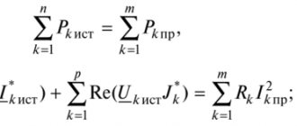
A comprehensive method for analyzing steady-state processes in linear electrical circuits:
Analysis (calculation) of an electrical circuit consists of determining the circuit's response (reaction) to incoming influences. In this case, influence means the inclusion of voltage and current sources in the circuit. In the general case, the response refers to all currents in the branches and all voltages on passive elements. Therefore, to calculate an electrical circuit means to find all the currents and all the voltages in this circuit.
To simplify the calculation of the circuit under harmonic influence, it is carried out using a complex method. It consists in the fact that when calculating, all harmonic functions (originals of currents, voltages, sources) are replaced with complex images (symbols), and all passive elements represent them with complex resistances. After determining the complex currents and voltages (response images), their originals (real instantaneous values) are found using the Euler formula.
Originals, values and images of sinusoidal currents and voltages
Sinusoidal current and voltage in real form (originals) are written as
where are the vibration amplitudes; — initial phases of oscillations.
Average and effective values of a sinusoidally varying quantity. The average value of current and voltage is taken to be their average value over half a period. Average current
Likewise
RMS current value
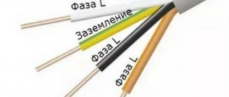
Likewise
Instantaneous complex values (images, symbols) of sinusoidal current and voltage:
where is the complex current amplitude; — complex current (complex effective current value): — complex voltage amplitude; — complex voltage (complex effective value of voltage).
Circuit with capacitive element
Capacity C
–
this is a parameter that characterizes the ability of a device to accumulate electrical charges q if a voltage u is applied to this device
.
Capacitive element
is
an ideal capacitor, which consists of two conducting plates of area S, separated by a dielectric layer of thickness d
.
An ideal capacitor is considered to be one in which the conductivity of the dielectric layer is zero (there is no leakage current) and the dielectric constant ε
is a constant value. From a school physics course we know the formula for the capacitance of an ideal flat capacitor.
can be more strictly defined as a coefficient of proportionality between the charge q and the voltage u that created this charge
:
| (30) |
q = Cu
On electrical diagrams, a capacitive element is depicted as two parallel straight segments of the same length (Fig. 19).
If the capacitor is connected to a direct current source, then the process of charging it will occur, as a result of which a voltage U
source, and the charging current will stop, since the insulation layer between the plates will not allow direct current to pass through.
The capacitor behaves differently when it is connected to an alternating current circuit, since the polarity of the voltage on its plates changes with double the frequency of the supply network (at a frequency of ƒ
= 50 Hz – one hundred times per second). That is, the plates are recharged, and an alternating current flows through the wires of the supply line, caused by the directional movement of electrons in metal conductors.
an electric displacement current flows in it
, associated with the directional orientation of charges inside dielectric molecules (dipoles).
Let's consider a sinusoidal current circuit with an ideal capacitive element (Fig. 19).
Let us assume that the voltage at the input terminals of the circuit does not contain the initial phase ( ψU
= 0),
| (31) |
Let us substitute (31) into the right side of equality (30)
| (32) |
As is known, electric current (directed movement of charges) in the general case can be represented mathematically as the rate (derivative) of charge change over time. Taking into account dependence (32), we obtain
| (33) |
Comparing equalities (31) and (33), we can verify that in a circuit with a capacitive element, the current leads the voltage by a quarter of a period
(
π/
2, 90°).
On the right side of equality (33) we introduce the notation Im
current amplitude
| (34) |
where is capacitance
.
The equality itself represents Ohm's law for the amplitude
values of current and voltage.
Dividing both sides of this equality by , we obtain Ohm's law for effective values
:
| (35) |
Instantaneous power of a circuit with capacitance C
:
| (36) |
Period average (active) power P
:
| (37) |
Thus, as in a circuit with an ideal inductive element, in a circuit with a capacitor there is no irreversible process of conversion of electrical energy, but there is an exchange of energy between the capacitor and the supply network.
Figure 20a shows a vector diagram of the amplitude values of the current Im
and voltage
Um
for time
t
= 0 with the development of the corresponding sinusoids in graphs (Fig. 20b), as well as with the construction of a graphical dependence of the instantaneous power
p= UIsin
2
ωt
.
Let us consider in more detail the reversible process of energy conversion in the circuit under consideration. In the first quarter of the period T/
4 (Fig. 20b) instantaneous power is positive, that is, electrical energy comes from the network, and the process of charging the capacitor occurs: the voltage on the capacitor plates increases from 0 to a positive amplitude +
Um
, electrical energy is converted into electric field energy [1].
| (38) |
In the second quarter of the period, the instantaneous power is negative ( p
< 0), and the capacitor is discharged: the current changes polarity, the voltage drops to zero, the energy of the electric field (38) turns into electricity and returns back to the supply network. Next, a similar process occurs with the polarity of the capacitor plates changing to the opposite, etc.
Rice. 20
Thus, in a circuit with a capacitive element:
1. Current leads voltage by a quarter of a period
(
π
/2).
2. Ohm's law is valid only for amplitude and effective values of voltage and current
.
At the same time, the concept of capacitance is introduced
.
3. Instantaneous power pulsates at double frequency relative to the average value P = 0
.
This means that the energy conversion process in the circuit under consideration is reversible
,
that is, energy is exchanged between the capacitor and the supply network
.
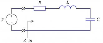
1.8. Circuit with series connection r
,
L
and
C
Figure 21 shows a single-phase electrical circuit with a resistive r
, inductive
L
and capacitive
C
elements.
The circuit is closed to a source E of infinite power
[2], that is, the condition is met (
U
is the effective value of the sinusoidal voltage at the input of the circuit).
Rice. 21
Let us write in vector form Kirchhoff’s second law for effective voltage values in relation to the circuit under consideration (Fig. 21):
| (39) |
Equality (39) as Kirchhoff’s second law can be read as follows.
In a closed electrical circuit, the geometric sum of the vectors of the effective values of the emf.
(in this case it is only voltage)
is equal to the geometric sum of the vectors of the effective values of the voltage drops on the elements forming this circuit
(here this sum).
Since in a series circuit (Fig. 21) the current I
in all three elements
r, L
and
C
are the same, then, in accordance
with Ohm’s law, for a section of the circuit
we can write expressions for the absolute values of the terms of the vectors:
Ua
=
Ir
,
UL
=
IxL
,
UC
=
IxC
.
I
and the corresponding voltage drops
φa
= 0,
φL
= +
π
/2,
φC
= –
π
were established , which allows the vectors and relative the total current vector and find the total vector at the input of the circuit (Fig. 21).
Let us consider the procedure for constructing a vector diagram of a sequential circuit (Fig. 21) in accordance with equality (39).
Previously (Fig. 14, 17 and 20), vector diagrams were constructed for the amplitude values of current (or voltage) sinusoids in relation to time t
= 0, when the original sinusoid had a zero initial phase (
ψI
= 0 or
ψU
= 0), which allowed this sinusoid to be represented by an amplitude vector in the form of a horizontal vector with an arrow to the right (Fig. 14, 17, 20).
Let us keep this technique for the circuit under consideration, specifying a current sinusoid with a zero initial phase ψI
= 0:
| (40) |
where is the current amplitude.
Then the vector of the effective current value I
for time
t
= 0 will be directed as shown in Figure 22 a, b.
Choosing a scale for stresses
, let us depict the vectors taking into account the shift angles
φa
= 0,
φL
= +
π
/2 and
φC
= –
π
/2, aligning their origins with the origin of the vector (Fig. 22a).
By rotating all four vectors counterclockwise with angular frequency ω
, you can make sure that the line passing through, shown in the dotted line in the figure, is first crossed by the vector, after a quarter of the period - by the corresponding vectors and, and after another quarter of the period - by the vector (respectively
φL
= +
π
/ 2,
φa
= 0,
φC
= –
π
/2).
Rice. 22
Let us consider in detail the procedure for constructing a vector diagram of a sequential circuit in accordance with equality (39), using the well-known method of adding several vectors according to the polygon rule
.
According to this rule, having chosen one of the vectors as the first term, the remaining vector terms by means of parallel transfer combine the beginnings with the ends of the previous terms of the vectors. By connecting the beginning of the first term of the vector with the end of the last, we obtain the total vector
.
Having given the direction of the vector, we take the vector as the first term (Fig. 22b). As the second term, we construct a vector by parallel translation from Figure 22a, aligning its beginning with the end of the vector. Having performed a similar operation with the third term, we obtain the resulting voltage vector at the input of the circuit by connecting the beginning of the first term of the vector with the end of the third (Fig. 22b).
Obviously the resulting vector diagram is a graphical solution of Kirchhoff's second law
, since it satisfies equation (39).
As can be seen from the vector diagram in Figure 22b, in a shaded vector right triangle, the leg opposite to the angle φ
is a vector whose length
Up
is equal to the algebraic difference
Up
=
UL
–
UC
, since the vectors and are in antiphase, that is, shifted by an angle of 180°.
The resulting vector is called " reactive voltage
".
Since UL
=
IxL
,
UC
=
IxC
., then
| (41) |
where is the reactance
.
Applying the Pythagorean theorem to the stress triangle (Fig. 22b), we obtain
| (42) |
where is the total or apparent resistance
.
Let us rewrite equality (42) in the form
| (43) |
which represents Ohm's law for a series circuit
, read as follows:
the current is directly proportional to the voltage at the input of the circuit
.
The proportionality factor for a series circuit is the factor 1
/z.
As can be seen from the vector diagram (Fig. 22b), the voltage vector leads the current vector by an angle φ
(taking into account the direction of rotation of the vectors counterclockwise).
This is explained by the fact that in the case under consideration the circuit is inductive in nature, that is, xL
>
xC
and
UL
>
UC
.
The sign of such an angle φ is usually considered positive
. Obviously, for the case under consideration, we can write an expression for the instantaneous value of the voltage sinusoid
| (44) |
Dividing all sides of the vector voltage triangle (Fig. 23a) by the same current value I
, we obtain a scalar resistance triangle similar to the original one (Fig. 23b) with sides
.
Rice. 23
If we multiply the sides of the voltage triangle by the current value I
, or the sides of the resistance triangle per square of the current
I
2, then we get another similar power triangle (Fig. 23c) with the sides:
R
=
Ua I
=
I
2
r
–
active power
[W];
Q
=
Up I
=
I
2
x
–
reactive power
[var];
S
=
UI
=
I
2
z
–
total or apparent power
[VA].
As you know, the dimension of the power unit is the watt (W), which is the product of the dimensions of voltage and current [W[ = [V] × [A]. In relation to alternating current circuits, it is customary to distinguish three types of power units, although their dimensions are the same:
− W
(watt) – unit of active (period-average) power;
− var
(volt-ampere reactive) – unit of reactive power;
− VA
(volt-ampere) – a unit of measurement of total (apparent) power.
Thus, the concept of power in an electrical circuit of sinusoidal current is much broader than in DC circuits, although the unit of measurement is the same, namely “watt”.
Obviously the instantaneous power p
at the input of the series circuit under consideration
is equal to the product of the voltage sinusoid and the current sinusoid
, that is, it is necessary to multiply the right-hand sides of equalities (44) and (40):
| (45) |
After a series of transformations on the right side of equality (45), discussed in detail in [1], we can obtain an expression for instantaneous power in the form:
| (46) |
where P
=
Scosφ
– active (period average) power;
S
=
UI
– total (apparent) power (Fig. 23c).
As can be seen from equality (46), the instantaneous power p pulsates with double frequency
2
ω relative to the average (active) power P, and the amplitude of the double-frequency cosine wave at φ
¹ 0
is greater than the average value
(
S
>
P
), that is, the instantaneous power graph will have negative sections within the angle
φ
¹ 0 (Fig. 27b).
Complex resistance and conductance of the circuit
When calculating a target using a complex method, the concept of complex resistance (conductivity) is introduced.
The complex resistance Z is the ratio of the complex voltage to the complex current caused by this voltage:
Three forms of recording complex resistance are used:
where is the total current resistance; — active resistance; — reactance; - phase difference between voltage and current.
Complex conductivity is the ratio of complex current to complex voltage
Based on expression (1.9)
where is the admittance; -conductance; — reactive conductivity.
The components of resistance and conductivity are related to each other by the following relationships:
Note. The concepts of complex resistance and complex conductance can refer to the entire circuit, to part of the circuit, or to its individual elements.
Basic laws of current flow in linear electrical circuits
Ohm's Law: Defines the relationship between current, voltage and resistance of a passive element (branch, section, circuit). The real form of the law is applicable only for resistance:
Ohm's law in complex form is valid for any passive element:
Kirchhoff's first law: Determines the balance of currents in any node of an electrical circuit. It can be represented as a real
or in complex form
where is the number of branches connected at a given node.
Kirchhoff's second law. Determines the voltage balance in any closed circuit circuit:
where is the number of passive elements in a closed circuit: is the number of sources included in this circuit.
Relationship between sinusoidal current and voltage in passive elements
In resistance, the real form of recording the relationship between current and voltage is determined by Ohm’s law:
In complex form (images) are defined by the expressions:
In resistance, current and voltage are always in phase, i.e.
In inductance, voltage and current are related by the relations:
Let us write these expressions in complex form:
where is the complex inductance resistance; — inductive reactance;
- complex conductivity of inductance; - inductive conductivity.
From formulas (1.20) and (1.21) it is clear that the current in the inductance lags in phase from the applied voltage by an angle .
In a capacitance, voltage and current are related by the following relationships:
In complex form, expressions (1.22) take the form:
where is the complex resistance of the capacitance; — capacitance; — complex conductivity of the capacitance; — capacitive conductivity.
From formulas (1.22) and (1.23) it is clear that the current in the capacitor is ahead of the applied voltage in phase by an angle .
Current and voltage diagrams
For greater clarity, time and vector diagrams are used when analyzing processes and calculating penalties.
A time diagram is a graph of instantaneous values of currents and voltages on a coordinate plane along the real time axis (Fig. 1.4). The initial phase reports from zero of the sine wave (or from the maximum of the cosine wave) to the origin. The initial phase is positive if the counting direction coincides with the direction of the time axis.
The phase shift of voltage and current is measured in the direction from zero voltage to zero current. If this direction coincides with the direction of the time axis, then the phase shift is positive.
A vector diagram is a set of vectors constructed on a complex plane with respect to mutual orientation in phase. The length of the vector is proportional to the amplitude of the vibration.
All vectors rotate counterclockwise in time at a speed of . Fig. 1.5 shows a vector diagram corresponding to the timing diagram shown in Fig. 1.4.
The initial phase is measured from the real axis to the vector. The phase shift is measured from the current vector to the voltage vector. The initial phase and phase shift are positive if their counting direction coincides with the direction of vector rotation (counterclockwise).
Basic quantities and methods for calculating an electrical circuit of alternating sinusoidal current
Definition 1
Alternating electric current is an electric current that changes in direction and magnitude over time (in some cases, only its magnitude changes).
In everyday life, alternating sinusoidal current is used for power supply.
Definition 2
Sinusoidal electric current is an electric current that changes over time according to a sinusoidal law.
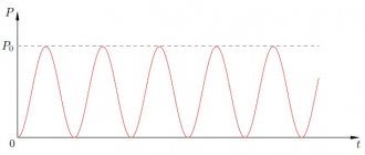
Graphically, the sinusoidal law is shown in the figure below.
Figure 1. Graph. Author24 - online exchange of student work
Are you an expert in this subject area? We invite you to become the author of the Directory Working Conditions
$I = Imsin * ((2pt / T) + φ) = Imsin * (wt + φ)$
where: Im – maximum value of the amplitude of the electric current; T – time during which one complete oscillation (period) occurs; f – number of oscillations per second (frequency); w – angular frequency; n = 3.14; — f — initial phase
The oscillation frequency is calculated using the following formula:
$f = 1 / T$
The angular frequency is calculated as follows:
$w = 2p * f = 2p / T$
Any sinusoidal function is determined by the following quantities, which are the main characteristics of alternating sinusoidal current:
- Angular frequency.
- Initial phase.
- Amplitude.
To calculate electrical circuits of alternating sinusoidal current, the following methods can be used:
- Operations with sinusoids.
- Conductivity method.
- Symbolic method.
- Method of nodal potentials.
- Loop current method.
- Equivalent generator method.
- Vector diagram method.