The power of technical equipment or power plants (devices, units) supplied by them to perform work is indicated in their technical characteristics. But this does not mean that all of it is used for its intended purpose to achieve results. Only useful power is used to perform work.
General definition of power
Types of DC power
Any power value is determined by the work that is done in a certain unit of time. Most often it becomes a second. It means a quantity that characterizes how quickly work is done. Regarding electrical power, this is the energy consumption per second.
The power characteristic of the current corresponds to the ratio of its work to time
Current work is the process of converting electricity into some other energy (mechanical, thermal or light). It is by power, which is designated by the letter “P” or “W,” that the performance of the electric current is assessed.
For your information! In general, a constant current does not have an active and reactive P. This type of network is characterized by only an instantaneous characteristic.
Instantaneous power
If we talk about alternating current networks, then the value in question in them, like electric current or voltage, regularly changes its values. This directly affects other parameters. With a constant flow of charges, everything remains unchanged. This is where the term “instantaneous power” comes from.
The forces in a regular current network remain unchanged and are equal to their instantaneous values taken at an arbitrary point in time. This characteristic can be calculated using instantaneous values. The formula for DC power in the circuit is suitable for this: P = I * U.
The value under consideration can be found from the product of electric current and voltage
If the network is passive and Ohm’s law is observed in it, then equality is true. In the case of connecting an EMF source, a different formula is needed: P = I * E, where E is the electromotive force.
Active power
Active power is the average value of instantaneous P over a period. With active P, current power is converted into energy of any type (mechanical, light or thermal). Such a transfer of electric current cannot be performed in the opposite direction. Active type is also measured in watts. 1 Watt is equal to 1 volt times 1 ampere.
The work is inextricably linked with the determination of power characteristics
For your information! On a domestic and even more so industrial scale, the unit of measurement watt is never used. For these purposes, indicators that are an order of magnitude higher are used: megawatts to kilowatts.
Reactive power
The reactive power characteristic determines the load that is created by electrical devices due to certain fluctuations in the energy of the electromagnetic field in sinusoidal current networks of variable frequency. It is equal to the product of the rms voltage and current values multiplied by the sine of the angle by which the phase shifts between them. The reactive parameter is inextricably linked with the full P and the active parameter.
All basic quantities can be found using Ohm's law
If we talk about the physical meaning of reactivity, then it represents a certain energy that is pumped from the source to the reactive elements of the receiver (capacitor, generator winding, inductor, etc.), and then returns back to the source during one oscillation period.
Full power
The total P of the electric current is the value corresponding to the product of the electric current and the voltage in the circuit. It is inextricably linked with active and reactive quantities and is determined by the following equation: where Sos = total power, and P and Q are its active and reactive characteristics, respectively.
Total power that can be represented as a glass of beer
To put it simply, active P exists wherever there is an active load. For example, in spiral heaters, wire resistance, etc. The reactive parameter is characteristic of the reactive load that is present in the inductive or capacitive elements.
RESULTS
1 ÐÑ (ваÑÑ) — моÑноÑÑÑ Ñока в 1 Ð (ампеÑ) в пÑоводнР¸ÐºÐµ, Ð¼ÐµÐ¶Ð´Ñ ÐºÐ¾Ð½Ñами коÑоÑого поддеÑжи 1 Ð (волÑÑ).
RESULTS ¾Ð³Ð¾ Ñока назÑваеÑÑÑ Ð²Ð°ÑÑмеÑÑ. RESULTS OPTIONAL RESEARCH ÑмеÑÑа.
ROOM СОС), рьр ÑÑ) и дÑ. UR ´Ð¸Ð½Ð¸ÑÑ Ð¸Ð·Ð¼ÐµÑÐµÐ½Ð¸Ñ ÑабоÑÑ, коÑоÑÑе ÑаÑÑо иÑп¾Ð»Ñ зÑÑÑ Ð² бÑÑÑ, напÑÐ¸Ð¼ÐµÑ (киловаÑÑ·ÑаÑ). Ratio 1ÐºÑ = 103ÐÑ, а 1Ñ = 3600Ñ, Ñо
1кÐÑÂ·Ñ = 103ÐÑ·3600Ñ = 3.6·106ÐÑÂ·Ñ = 3.6·106ж.
Definition and formula of useful power
It is worth considering the concept of useful power and the formula using the example of an electrical circuit. The power that the power source (PS), in particular current, develops in a closed circuit will be the total power.
Circuit diagram
The circuit includes: a current source with EMF (E), an external circuit with a load R and an internal circuit of a power supply whose resistance is R0. The formula for total (total) power is:
Ptotal = E*I.
Here I is the value of the current passing through the circuit (A), and E is the value of the emf (B).
Attention! The voltage drop in each section will be equal to U and U0, respectively.
So the formula will take the form:
Ptotal = E*I = (U + U0) *I = U*I + U0*I.
It can be seen that the value of the product U*I is equal to the power supplied by the source to the load and corresponds to the useful power Ppol.
The value equal to the product U0*I corresponds to the power that is lost inside the power supply for heating and overcoming the internal resistance R0. This is the power loss P0.
The values substituted into the formula show that the sum of useful and lost power makes up the total power of the IP:
Ptotal=Pfloor+P0.
Important! When operating any apparatus (mechanical or electrical), the useful power will be that which remains to perform the required work after overcoming the factors causing losses (heating, friction, counteracting forces).
Total, net power and efficiency of the DC circuit
Consider a closed unbranched circuit consisting of a current source and a resistor. Let us apply the law of conservation of energy to the entire circuit:
It will be interesting➡ Schemes and methods of connecting electric motors
Since , and for a closed circuit points 1 and 2 coincide, the power of electrical forces in the closed circuit is zero. This is equivalent to the statement about the potentiality of the direct current electric field, which was already mentioned earlier.
So, in a closed circuit, all the heat is released due to the work of external forces: , or , and we again come to Ohm’s law, now for a closed circuit: .
The total power of the circuit is the power of external forces, it is also equal to the total thermal power:
Useful is the thermal power released in the external circuit (regardless of whether it is useful or harmful in this particular case):
The role of electrical forces in a circuit. In the external circuit, at load R
, electric forces do positive work, and when moving a charge inside a current source, they do negative work of the same magnitude. In the external circuit, heat is released due to the work of the electric field. The work given in the external circuit is “returned” by the electric field inside the current source. As a result, all the heat in the circuit is “paid for” by the work of external forces: the current source gradually loses the chemical (or some other) energy stored in it. The electric field plays the role of a “courier”, delivering energy to the external circuit. Dependence of total, useful power and efficiency on load resistance R. These dependencies are obtained from formulas (1 – 2) and Ohm’s law for the complete circuit:
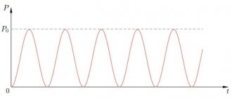
You can see the graphs of these dependencies in the figure.
The total power decreases monotonically with increasing , because the current in the circuit decreases. The maximum total power is released at , i.e. in case of short circuit
Examples of problem solving
Task 1.
The battery consists of
n
= 5 series-connected cells with
E
= 1.4 V and internal resistance
r
= 0.3 Ohm each. At what current is the useful power of the battery equal to 8 W? What is the maximum usable power of the battery?
Given:
Solution
n
=
5 When the elements are connected in series, the current in the circuit
E
= 1.4 V (1)
R
a
= 8 W From the useful power formula we express
external resistance R
and substitute into formula (1)
I
—
? -?
after transformations we obtain a quadratic equation, solving which we find the value of the currents:
A; I
2 =
A.
So, at currents I
1 and
I
2 the useful power is the same.
When analyzing the graph of the dependence of useful power on current, it is clear that at I
1 the power losses are lower and the efficiency is higher.
Useful power is maximum at R
= n r
;
R
= 0.3 Ohm.
Answer
: I
1 = 2 A;
I
2 =
A;
P
amax =
Tue
Task 2.
The useful power released in the external part of the circuit reaches a maximum value of 5 W at a current of 5 A. Find the internal resistance and emf of the current source.
Given:
Solution
P
amax = 5 W Useful power (1)
I
= 5 A according to Ohm's law (2)
Net power is maximum at R
=
r
, then from
r
- ?
E
- ? formula (1) 0.2 Ohm.
From formula (2) B.
Answer:
r
= 0.2 Ohm;
E
= 2 V.
Task 3.
A generator with an EMF of 110V is required to transmit energy over a distance of 2.5 km via a two-wire line. Power consumption is 10 kW. Find the minimum cross-section of copper supply wires if power losses in the network should not exceed 1%.
Given:
Solution
E =
110V Wire Resistance
l
= 510 3 m where
is the resistivity of copper;
l
– length of wires;
R
a =
10 4 W
S
– cross section.
= 1.710 -8 Ohm. m Power consumption P
a = I E
, power lost
P
pr =
100 W in the network
P pr = I
2
R pr
, and since in the pipelines and the consumer
S
- ? the current is the same, then
where
Current power formula. Actual and rated power. Electrical appliance efficiency:
All known electrical devices operate using electrical energy. As a result of this, we receive light, heat, sound, mechanical movement, that is, different types of energy. In this article we will consider and study such physical concepts as electric current power.
By current power, as in mechanics, we mean the work that is performed per unit of time. A physical formula will help you calculate power, knowing the work performed by electric current over a certain period of time.
- Current, voltage, power in electrostatics are related by an equality that can be derived from the formula A = UIt. It is used to determine the work performed by electric current:
- P = A/t = UIt/t = UI Thus, the formula for direct current power at any section of the circuit is expressed as the product of the current and the voltage between the ends of the section.
Using Ohm's law, the current power formula P = UI is written as follows:
P = UI = U2/R = I2/R So, the power released on the conductors is directly proportional to the current flowing through the conductor and the voltage at its ends.
As you know, ideal machines and mechanisms do not exist (that is, those that would completely convert one type of energy into another or generate energy).
During operation of the device, part of the expended energy is necessarily spent on overcoming unwanted resistance forces or is simply “dissipated” into the environment.
Thus, only part of the energy we expend goes to perform useful work, for which the device was created.
A physical quantity that shows what part of the useful work is expended is called the efficiency factor (hereinafter referred to as efficiency).
- In other words, efficiency shows how efficiently the work expended is used when it is performed, for example, by an electrical appliance.
- Efficiency (denoted by the Greek letter η (“this”)) is a physical quantity that characterizes the efficiency of an electrical device and shows what part of the useful work is expended.
- Efficiency is determined (as in mechanics) by the formula:
- η = AP/AZ 100%
- If the power of the electric current is known, the formulas for determining the CFC will look like this:
- η = PP/PЗ 100%
- Before determining the efficiency of some device, it is necessary to determine what is useful work (what the device is designed to do) and what is expended work (the work being done or how much energy is expended to do useful work).
21. The principle of operation of a centrifugal pump.
Device:
The main working body of a central-carbon pump is a freely rotating wheel mounted on a shaft inside a spiral housing. Between the wheel disks there are blades, smoothly curved in the direction opposite to the direction of rotation of the wheel. The inner surfaces of the disks and the surfaces of the blades form the so-called. inter-blade channels of the wheel, filled with pumped liquid during operation. The suction and injection of liquid occurs uniformly and continuously under the influence of the centrifugal force that occurs when the wheel rotates.
Principle of operation:
When the fluid passes from the impeller channel to the housing, a sharp decrease in speed occurs, as a result of which the kinetic energy of the fluid is converted into potential pressure energy, which is necessary to supply the fluid to a given height. In this case, a vacuum is created in the center of the wheel, and as a result, liquid continuously flows through the suction pipeline into the pump housing, and then into the inter-blade channels of the impeller. If the suction pipeline and housing are not filled with liquid before starting the central-wheel pump, then the resulting vacuum will not be enough to lift liquid into the pump (due to the gaps between the wheel and the housing). To prevent liquid from overflowing from the pump, a check valve is installed on the suction pipeline. To drain liquid, there is an expanding spiral-shaped chamber in the pump body: liquid first enters this chamber and then into the discharge pipeline.
Formula for useful power of current source
Let the electrical circuit consist of a current source having resistance $r$ and a load (resistance $R$). We find the power of the source as:
[P=?I left(7right),]
where $?$ is the EMF of the current source; $I$ – current strength. In this case, $P$ is the total power of the circuit.
Let us denote $U$ as the voltage on the external section of the circuit, then we present formula (7) in the form:
[P=?I=UI+I^2r=P_p+P_0left(8right),]
where $P_p=UI=I^2R=frac{U^2}{R}(9)$ – useful power; $P_0=I^2r$ – loss power. In this case, the source efficiency is determined as:
The maximum useful power (power at the load) is produced by the electric current if the external resistance of the circuit is equal to the internal resistance of the current source. Under this condition, the useful power is equal to 50% of the total power.
During a short circuit (when $Rto 0;;Uto 0$) or in idle mode $(Rto infty ;;Ito 0$), the useful power is zero.
Video
Source
8.5. Thermal effect of current
8.5.1. Current source power
Total power of the current source:
P total = P useful + P losses,
where P useful is useful power, P useful = I 2R; P losses - power losses, P losses = I 2r; I is the current strength in the circuit; R - load resistance (external circuit); r is the internal resistance of the current source.
Total power can be calculated using one of three formulas:
P full = I 2(R + r), P full =ℰ2R+r, P full = Iℰ,
where ℰ is the electromotive force (EMF) of the current source.
Useful power is the power that is released in the external circuit, i.e. on a load (resistor), and can be used for some purposes.
Net power can be calculated using one of three formulas:
P useful = I 2R, P useful = U2R, P useful = IU,
where I is the current strength in the circuit; U is the voltage at the terminals (clamps) of the current source; R - load resistance (external circuit).
Power loss is the power that is released in the current source, i.e. in the internal circuit, and is spent on processes taking place in the source itself; The power loss cannot be used for any other purposes.
Power loss is usually calculated using the formula
P losses = I 2r,
where I is the current strength in the circuit; r is the internal resistance of the current source.
During a short circuit, the useful power goes to zero
P useful = 0,
since there is no load resistance in the event of a short circuit: R = 0.
The total power during a short circuit of the source coincides with the loss power and is calculated using the formula
Pfull=ℰ2r,
where ℰ is the electromotive force (EMF) of the current source; r is the internal resistance of the current source.
Relationship between useful power and efficiency
Efficiency factor (efficiency) is a dimensionless quantity, expressed numerically as a percentage. Efficiency is denoted by the letter η.
The formula looks like:
η = A/Q,
Where:
- A – useful work (energy);
- Q – energy expended.
As the efficiency increases in various engines, it is permissible to build the following line:
- electric motor – up to 98%;
- ICE – up to 40%;
- steam turbine – up to 30%.
In terms of power, efficiency is equal to the ratio of useful power to the total power delivered by the source. In any case, η ≤ 1.
Important! Efficiency and Ppol are not the same thing. In different work processes, they achieve the maximum of one or the other.
Obtaining maximum energy at the output of the IP
For your information. To increase the efficiency of cranes, injection pumps or aircraft engines, it is necessary to reduce the friction forces of mechanisms or air resistance. This is achieved by using a variety of lubricants, installing higher-class bearings (replacing sliding with rolling), changing the wing geometry, etc.
The maximum energy or power at the output of the IP can be achieved by matching the load resistance Rн and the internal resistance R0 of the IP. This means that Rн = R0. In this case, the efficiency is 50%. This is quite acceptable for low-current circuits and radio devices.
However, this option is not suitable for electrical installations. To avoid wasting large amounts of power, the operating mode of generators, rectifiers, transformers and electric motors is such that the efficiency is approaches 95% and above.
Achieving maximum efficiency
The formula for the efficiency of a current source is:
η = Pн/Ptotal = R/Rн+r,
Where:
- Pn – load power;
- Ptotal – total power;
- R is the total resistance of the circuit;
- Rн – load resistance;
- r – internal resistance of IT.
As can be seen from the graph shown in Fig. higher, the power Pn tends to zero as the current in the circuit decreases. The efficiency, in turn, will reach its maximum value when the circuit is open and the current is zero; if there is a short circuit in the circuit, it will become zero.
If we look at an elementary heat engine consisting of a piston and a cylinder, then its compression ratio is equal to the expansion ratio. Increasing the efficiency of such a motor is possible if:
- initially high parameters: pressure and temperature of the working fluid before expansion begins;
- bringing their values closer to environmental parameters at the end of expansion.
Achieving ηmax is possible only with the most effective change in the pressure of the working component in the rotational movement of the shaft.
For your information. The thermal efficiency increases with increasing proportion of heat supplied to the working fluid, which is converted into work. The supplied heat is divided into two types of energy: internal in the form of temperature and pressure energy.
It will be interesting➡ Resistivity for common materials
Mechanical work, in fact, is performed only by the second type of energy. This gives rise to a number of disadvantages that slow down the process of increasing efficiency:
- some of the pressure goes to the external environment;
- achieving maximum efficiency is impossible without increasing the percentage of pressure energy used for conversion into work;
- it is impossible to increase the efficiency of heat engines without changing S the surface of pressure application, and without removing this surface from the point of rotation;
- the use of only a gaseous working fluid does not contribute to increasing η of heat engines.
To achieve a high efficiency of a heat engine, you need to make a number of decisions. The following device models contribute to this:
- introduce another working fluid with different physical properties into the expansion cycle;
- make the most of both types of energy of the working fluid before expansion;
- generate additional working fluid directly during gaseous expansion.
Information. All modifications to internal combustion engines in the form of: a turbocharger, the organization of multiple or distributed injection, as well as increasing air humidity, bringing the fuel to a state of steam during injection, did not produce tangible results in a sharp increase in efficiency.
Reactive coefficient
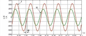
In another way, it is called the power factor and is a dimensionless quantity introduced to calculate the reactive component. Scientifically speaking, it shows how much the phase of the alternating current flowing through the load shifts from the voltage that appears across it. Numerically, it is taken to be equal to the cosine of the shift. Mathematically, this shift is interpreted as the cosine of the angle between the vector values of current and voltage.
In simple words, the power factor, denoted φ, indicates that part of the consumed electricity that is converted into useful work. For example, with cos φ = 0.9, ninety percent of the total energy will be spent on performing a useful action, and the remaining ten will be considered losses. Therefore, if the passport for any device indicates that the power of the product is 500 W, and cos φ = 0.5, then its total energy consumption will be 500/0.5 = 250 VA.
That is, the coefficient φ is found from the ratio of the energy consumed by the device to the total power value. Often, the equipment passport also indicates the component φ (the nature of the load). It can be resistive-capacitive or resistive-inductive. In this case, the coefficient itself is respectively leading or lagging.
If the voltage in the circuit changes according to a sinusoidal law, and the current according to a non-sinusoidal law, then the load will not have any reactive component, and the coefficient is assumed to be equal to the main wave (first harmonic). Non-sinusoidal refers to distortions of the electrical signal associated with harmonics that dominate the fundamental frequency.
In mathematics, the formula for finding the power factor is the expression: cos φ= P/S. Therefore, the higher its value, the less energy the device consumes from the network. There are various ways to raise the value of cos φ, even to a maximum value of one, called correction. The most effective is to add a complex electronic unit to the circuit, placed at the input of the device.
RESULTS
RESULTS , registry ´Ð¸Ð½Ð¸ÑÑ Ð²Ñемени. RESULTS, RESULTS, RESULTS ½ÑÐµÑ ÑлекÑÑиÑеÑкий Ñок за некоÑоÑÑй пÑомеж ÑÑок вÑемени, п ROLLING UP.
ROOM, ROOM ROOM из ÑоÑмÑÐ»Ñ A = UIt. ROOM REPORT:
P = A/t = UIt/t = UI ASSURANCE CONDITIONS ¸ ROOM RESULTS °ÑÑка.
Definition and formula of useful power
It is worth considering the concept of useful power and the formula using the example of an electrical circuit. The power that the power source (PS), in particular current, develops in a closed circuit will be the total power.
Circuit diagram
The circuit includes: a current source with EMF (E), an external circuit with a load R and an internal circuit of a power supply whose resistance is R0. The formula for total (total) power is:
Ptotal = E*I.
Here I is the value of the current passing through the circuit (A), and E is the value of the emf (B).
Attention! The voltage drop in each section will be equal to U and U0, respectively.
So the formula will take the form:
Ptotal = E*I = (U + U0) *I = U*I + U0*I.
It can be seen that the value of the product U*I is equal to the power supplied by the source to the load and corresponds to the useful power Ppol.
The value equal to the product U0*I corresponds to the power that is lost inside the power supply for heating and overcoming the internal resistance R0. This is the power loss P0.
The values substituted into the formula show that the sum of useful and lost power makes up the total power of the IP:
Ptotal=Pfloor+P0.
Important! When operating any apparatus (mechanical or electrical), the useful power will be that which remains to perform the required work after overcoming the factors causing losses (heating, friction, counteracting forces).
Power supply parameters
In practice, you often have to think about what the power of the current source should be, how many watts (W) or kilowatts (kW) are needed to ensure uninterrupted operation of the device. To understand the essence, you need to have an understanding of such concepts used in physics as:
- total circuit energy;
- EMF and voltage;
- internal resistance of the power supply;
- losses within the individual entrepreneur;
- useful power.
Regardless of what kind of energy the source produces (mechanical, electrical, thermal), its power should be selected with a small margin (5-10%).
When a load is connected to the circuit, which will consume energy from a current source (IT), the current will do work. The energy released by all consumers and circuit elements included in the circuit (wires, electronic components, etc.) is called total energy. The energy source can be any: generator, battery, thermal boiler. The total energy value will be the sum of the energy spent by the source on losses and the amount spent on performing specific work.
What is the difference between these two concepts?
EMF is electromotive force, it is the voltage that external forces (chemical reaction, electromagnetic induction) create inside a current source (IT). EMF is the force of movement of electrical charges in IT.
EMF definition
For your information. It seems possible to measure the value of E (EMF) only in idle mode (idle). Connecting any load causes a loss of voltage inside the power supply.
Voltage (U) is a physical quantity representing the potential difference ϕ1 and ϕ2 at the output of the voltage source (VS).
The definition of the concept of total power is used not only in relation to electrical circuits. It is also applicable to electric motors, transformers and other devices capable of consuming both active and reactive components of energy.
Similar losses occur at the internal resistance of a two-terminal network. For a battery, this is the electrolyte resistance; for a generator, this is the winding resistance, the lead wires of which come out of the housing.
You won’t be able to simply measure R0 with a tester; you definitely need to know it to calculate P0 losses. Therefore, indirect methods are used.
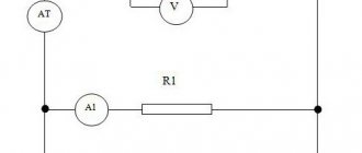
An indirect method for determining R0 is as follows:
- in x.x mode measure E (B);
- when the load Rн (Ohm) is turned on, Uout (V) and current I (A) are measured;
- The voltage drop inside the source is calculated using the formula:
U0=E-Uout.
At the last stage, R0=U0/I is found.
Circuit for measuring R0
Dependence of power on current, power formula, physical meaning
The first mention of electricity is found in the experiments of the ancient Greek philosopher Thales. It was he who first discovered that objects attract when rubbed. The term of the same name was introduced at the beginning of the 17th century by the English physicist Gilbert, after experiments carried out with magnets. The French scientist Coulomb is considered the father of the science of electricity - it was after the discovery of the law that received his name that electrical engineering began its victorious march, which continues to this day. This law states that two point charges in an airless environment interact with a force directly proportional to their modules and inversely proportional to the distance between them squared. Let's find out what the concept of electricity is?
It will be interesting➡ What is a phase in electricity?
In short, this is the directed movement of a flow of charged particles. The bodies through which they pass are called conductors. Each conductor has a certain resistance to electric current, which
And, before moving on to the basic laws, a few words about charged particles: they can be, relatively speaking, positive and negative. Like charges repel, and unlike charges attract.
Now, let's move on to the main thing
The basis of the science of electricity is Ohm's law.
An experiment carried out by this German physicist led him to the following belief: the current I passing through a metal conductor is proportional to the voltage at its ends, or I = U/R
Here, voltage is the difference, figuratively speaking, of “pressures” created by two points in an electrical circuit. It is measured in volts.
Electric current is the number of electrons that a section of an electrical circuit allows through and is measured in amperes. Resistance is the property of a chain to prevent this movement. In honor of the aforementioned physicist, it is measured in ohms.
In other words, a conductor through which a current of 1 ampere passes at a voltage of 1 volt has a resistance of 1 ohm.
All other electrical equipment “dances” because of this.
About the power of electric current
In physics, power is the rate at which work is performed. It doesn't matter which one. The faster this operation is carried out, the greater the power of the person performing it, be it a person, a mechanical device or something else, is considered.
The same is the case with electric current: its power is the ratio of the work done by moving electric charges to the period of time it took for this to happen.
Simply put, in order to obtain 1 watt of electrical power when the current source has a voltage of 1 volt, it is necessary to pass a current of 1 ampere through the conductor. In other words, power (P) can be calculated by multiplying electrical voltage and current by each other:
P = U*I.
Having remembered this simple formula, in practice you can calculate the power. For example, if the values of current and resistance are known, but there is no information about voltage, we can use Ohm’s law by substituting I * R into the formula instead. It turns out that the power is equal to the square of the electric current multiplied by the resistance.
This law will also come to the rescue if the voltage and resistance values are known. In this case, substituting I = U/R instead of the current value, we obtain a power value equal to the square of the voltage divided by the resistance.
Torque
This term has several synonyms: torque, motor torque, torque, torque. All of them are used to denote one indicator, although from the point of view of physics these concepts are not always identical.
In order to unify terminology, standards have been developed that bring everything to a single system. Therefore, in technical documentation the phrase “torque” is always used. It is a vector physical quantity that is equal to the product of the vector values of force and radius. The radius vector is drawn from the axis of rotation to the point of applied force. From a physics perspective, the difference between torque and torque lies in the point at which the force is applied. In the first case it is an internal effort, in the second it is an external one. The value is measured in newton meters. However, in the electric motor power formula, torque is used as the main value.
It is calculated as
M = F × r, where:
M — torque, Nm;
F is the applied force, H;
r—radius, m.
To calculate the rated torque of the drive, use the formula
Mnom = 30Рnom ÷ pi × nnom, where:
Rnom - rated power of the electric motor, W;
nnom - nominal speed, min-1.
Accordingly, the formula for the rated power of the electric motor should look like this:
Pnom = Mnom * pi*nnom / 30.
Usually all characteristics are indicated in the specification. But it happens that you have to work with completely new installations, information about which is very difficult to find. To calculate the technical parameters of such devices, data from their analogs is taken. Also, only the nominal characteristics that are given in the specification are always known. Real data must be calculated independently.
Efficiency of an electrical appliance
As you know, ideal machines and mechanisms do not exist (that is, those that would completely convert one type of energy into another or generate energy).
During operation of the device, part of the expended energy is necessarily spent on overcoming unwanted resistance forces or is simply “dissipated” into the environment.
Thus, only part of the energy we expend goes to perform useful work, for which the device was created.
A physical quantity that shows what part of the useful work is expended is called the efficiency factor (hereinafter referred to as efficiency).
- In other words, efficiency shows how efficiently the work expended is used when it is performed, for example, by an electrical appliance.
- Efficiency (denoted by the Greek letter η (“this”)) is a physical quantity that characterizes the efficiency of an electrical device and shows what part of the useful work is expended.
- Efficiency is determined (as in mechanics) by the formula:
- η = AP/AZ 100%
- If the power of the electric current is known, the formulas for determining the CFC will look like this:
- η = PP/PЗ 100%
- Before determining the efficiency of some device, it is necessary to determine what is useful work (what the device is designed to do) and what is expended work (the work being done or how much energy is expended to do useful work).
General characteristics of engines
All motors have common parameters that are used in the formula for determining the power of an electric motor. Based on them, the properties of the machine can be calculated. In different literature they may be called differently, but they mean the same thing. The list of such parameters includes:
- Torque.
- Engine power.
- Efficiency.
- Nominal speed.
- Rotor moment of inertia.
- Design voltage.
- Electrical time constant.
The above parameters are necessary, first of all, to determine the efficiency of electrical installations operating due to the mechanical force of motors. Calculated values give only an approximate idea of the actual characteristics of the product. However, these indicators often use electric motor power in the formula. It is this that determines the performance of the machines.