- What is electrical capacity
Electrical capacity:
By giving the body a certain charge, we change its potential. This change is directly related to the amount of charge imparted to the body.
To study the dependence of the potential of a body on its charge, we will conduct an experiment with an electrometer, the body of which is connected to the surface of the Earth. 'The geek system can measure the potential of a body relative to the Earth. Let's attach a hollow metal ball to the rod of this electrometer and impart a charge to it using a small metal ball on an insulating handle. If you touch the inner surface of a metal ball with a charged ball, then all its charge will transfer to the ball, and the electrometer needle will show an increase in the potential of the ball. Consistently repeating the experiment with charge transfer to a large ball, we note that each time its potential increases (Fig. 1.28).
Using more accurate methods of measuring charge and potential, it can be established that the potential increases in proportion to the increase in charge. The potential is proportional to the charge on the ball. The results of one of these experiments are shown in the graph (Figure 1.29).
If we attach a ball of a larger (smaller) diameter to the electrometer rod and continue the experiments (Fig. 1.31), we will see that the charging speed has changed and decreased (increased) accordingly. The process of electrification of a ball of larger diameter is shown in the graph in Figure 1.32.
Comparing the graphs that illustrate the charging processes of balls of different diameters (Fig. 1.30 and 1.32), we see that the graphs have different slopes relative to the horizontal axis. This indicates that with the same charge values, balls of different diameters will have different potentials. It turns out that the relationship between the charge and potential of the ball is significantly influenced by the geometric dimensions of the balls.
Rice. 130. Electrification of a ball of larger diameter
The potential of a metal ball is proportional to its charge; The proportionality coefficient is different for different balls.
Analyzing the experimental results and the corresponding graphs, we can draw the following conclusions:
- The potential of each ball is proportional to its charge:
- For bodies of different sizes the coefficient of proportionality is different.
It has been established that this coefficient for each body has a very specific value, which reflects the body’s ability to accumulate electrical charge. A physical quantity equal to the ratio of the electric charge imparted to a body to its potential is called the electrical capacity of the body. where C is the electrical capacity of the conductor; Q - charge; φ is potential.
To measure electrical capacity in physics, a unit called the farad (F) is used.
A body has an electrical capacity of 1 farad if, when its charge changes by 1 coulomb, the potential changes by 1 volt:
An electrical capacity of 1 farad is found in bodies whose potential changes by 1 volt when the charge changes by 1 coulomb.
- 1F is a fairly large value of electrical capacitance. For example, the electrical capacity of the Earth, which has a radius of 6400 km, is only 7 ∙ 104 F. Therefore, in practice, a unit of electrical capacity that is a multiple of the farad is used:
- 1 microfarad = 1 µF = 10-5 F.
- 1 picofarad = 1 pF = 10-12 F.
Example:
Two balls, the electrical capacitances of which are 50 μF and 80 μF, and the potentials are 120 V and 50 V, respectively, are connected by a wire. Find the potential of the balls after connection.
| Given: C1 = 50 µF, C2 = 80 µF, φl = 120 V, φ2 = 50 V. | Solution The charge of each ball is correspondingly equal to: Q1 = C1φ1. Q2=c2φ2∙ |
| φ-? |
After connecting the balls, a redistribution of charges between them will occur so that their potentials become the same. According to the law of conservation of electric charges
From here
or
Substituting the values of physical quantities and making calculations, we get:
Answer: After connection, the balls will have a potential of 77 V.
Flat capacitor
There are many types of capacitors with different shapes and internal structures. Let's consider the simplest and most fundamental - a flat capacitor. A flat capacitor consists of two parallel conductor plates (plates), electrically insulated from each other by air or a special dielectric material (for example, paper, glass or mica).
History of charge storage
The earliest written evidence of the production of charges by friction belongs to the scientist Thales of Miletus (635-543 BC), who described the triboelectric effect from the interaction of amber and dry wool. For the next 2,300 years or so, any production of electricity involved rubbing two different materials against each other.
A qualitative breakthrough in knowledge about charges occurred during the Enlightenment - a period of revolutionary development of scientific thought in educated circles. At this time, electricity became a popular topic, and many experiments were carried out by enthusiasts with friction-based generators.
The first device for storing the resulting charges was created in 1745 by two electricians (as people who studied the nature of static electricity were then called), working independently of each other: Ewald von Kleist, dean of the cathedral in Prussia, and Pieter van Mussenbroeck, professor of mathematics and physics at the University of Leiden.
The discovery of the phenomenon occurred during experiments by both experimenters, but with the difference that Mussenbruck, firstly, made many improvements to the originally created equipment, and secondly, informed his colleagues in writing about his achievements. Very little time passed and scientists around the world began to create charge storage devices of their own designs. These were the first steps in the evolution of capacitors, which continues to this day. The main dates in the chronology of the appearance of devices for storing charges:
- 1746 - invention of the Leyden jar as a result of experiments to refine the Kleist device;
- 1750 - Benjamin Franklin's experiments with capacitor banks;
- 1837 - publication by Michael Faraday of the theory of dielectric polarization - the scientific basis for the operation of storage devices;
- end of the 19th century - the beginning of the practical use of Leyden jars together with the first direct current devices;
- beginning of the 20th century - invention of mica and ceramic capacitors.
Capacitor charge. Current
In terms of its purpose, a capacitor resembles a battery, but it is still very different in its operating principle, maximum capacity, and charging/discharging speed.
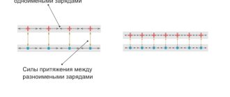
Let's consider the principle of operation of a flat-plate capacitor. If you connect a power source to it, negatively charged particles in the form of electrons will begin to collect on one plate of the conductor, and positively charged particles in the form of ions will begin to collect on the other. Since there is a dielectric between the plates, charged particles cannot “jump” to the opposite side of the capacitor. However, electrons move from the power source to the capacitor plate. Therefore, electric current flows in the circuit.
At the very beginning of connecting the capacitor into the circuit, there is the most free space on its plates. Consequently, the initial current at this moment encounters the least resistance and is maximum. As the capacitor fills with charged particles, the current gradually drops until the free space on the plates runs out and the current stops completely.
The time between the states of an “empty” capacitor with a maximum current value, and a “full” capacitor with a minimum current value (i.e., its absence), is called the transition period of the capacitor charge.
Calculation
Calculation of the capacitance of the capacitor is done using a fairly simple formula:
In this formula:
- q is the amount of charge accumulated by the capacitor.
- φ1−φ2 is the potential difference between its plates.
This expression helps to quite easily calculate the capacitance of any flat-plate capacitor. As mentioned earlier in the article, this value of the electrical capacity of capacitors always depends on its geometric dimensions.
Flat capacitor
A distinctive feature of a flat-plate capacitor is the presence of two parallel plates. Such devices can have a square, round or rectangular shape.
Let us next consider how to determine the capacitance of this type of capacitor. The following formula will always help you find the capacitance of this type of capacitor:
Electrical capacity
Often, the use of capacitors involves connecting several such elements into a circuit at once. Thanks to this, the total capacity can be increased. The formula for determining the electrical capacity of a flat capacitor when connected in parallel is as follows:
Determining the total capacitance for such an electrical circuit is done as follows: C=C1+C2
The amount of charge and voltage for such a connection circuit is determined as follows:
qtot=q1+q2
Utot=U1=U2
The formula will allow you to determine the capacitance of a capacitor for a series connection of elements:
That is, in this case, the total electrical capacity of a flat capacitor is found using the expression:
1/Ctot=1/C1+1/C1
Using these expressions, we will find the total voltage and determine the amount of charge for a series connection of elements:
qtotal=q1=q2
Utot=U1+U2
The capacitance of the capacitor and the calculation formulas used for various connection options for flat devices are shown in the figure below. We can say that it is very visual and easy to use:
Spherical capacitor
The spherical device has two plates in the form of concentric spheres, between which a dielectric is located. The capacitance of a spherical capacitor can be determined as follows:
In this expression, the value “4π” determines the coefficient of charge dissipation on the surface of spherical planes.
The capacitance of a spherical capacitor can be calculated using the formula for a flat device if the gap is quite small compared to the radius of the sphere.
Cylindrical
The cylindrical device is slightly similar to the previously described spherical one. They use similar-shaped linings. They also have a round shape, which means that the calculation of the capacity of a cylindrical device will also be influenced by such a parameter as the radius of the plates. The difference lies only in the most elongated shape of the plates of the cylindrical capacitor. The capacity of a cylindrical capacitor is determined by the formula:
Spherical and cylindrical types of elements are highly dependent on the thickness of the dielectric layer. The thicker it is, the smaller the charge volume will be, which means its resistance to breakdown voltage will increase.
Capacitor charge. Voltage
At the very beginning of the charging transition period, the voltage between the plates of the capacitor is zero. As soon as charged particles begin to appear on the plates, a voltage arises between unlike charges. The reason for this is the dielectric between the plates, which “prevents” charges with opposite signs tending to each other from moving to the other side of the capacitor.
At the initial stage of charging, the voltage rises quickly because the high current very quickly increases the number of charged particles on the plates. The more the capacitor is charged, the lower the current, and the slower the voltage rises. At the end of the transition period, the voltage on the capacitor will completely stop growing and will be equal to the voltage on the power source.
As can be seen in the graph, the capacitor current directly depends on the change in voltage.
The formula for finding the capacitor current during the transition period is:
- Ic - capacitor current
- C - Capacitance of the capacitor
- ΔVc/Δt – Change in voltage across the capacitor over a period of time
General information
The word "condenser" is translated from Latin as "thickening". Therefore, a device that allows one to obtain a uniform electric field was called this term. In physics there is a clear definition of such a device. According to him, a capacitor is a system of two flat conductors the distance between which is much less than their dimensions. The first such device was the Leyden Jar.
In 1745, the Dutchman Pietervan Muschenbroek and his student Kuneus in the city of Leiden assembled a jar-shaped device designed for storing and accumulating charges. The device contained the following components:
- glass cylinder;
- outer and inner shells;
- wooden cork;
- wire conductor.
The shells covered approximately two-thirds of the vessel and were made of sheet tin. A metal rod passed through the stopper to ensure the seal of the jar. By touching the submariner with a charged body, the scientist transferred the charges into the container. Upon contact, electrons moved to the conductor and accumulated on the electrode. As a result, one plate of the capacitor was charged positively, and the other - negatively.
As it turned out, this design was capable of accumulating a supply of electricity. The invention of the first capacitor led to a deeper understanding of the nature of electricity. With its help, it became possible to understand the behavior of dielectrics and conductors and understand the mechanism of charge separation.
From a physical point of view, the following processes take place in the device. Two separated plates are charged by particles with different signs. The voltage vector of a positively charged conductor is directed away from it in all directions. In this case, the lines of force that are created between the plates do not depend on the distance, they are identical in magnitude and direction. Therefore, the same field is created on the outside of the negative plate, but with lines entering it.
Since the charges on the electrodes are the same, the field strength inside the plates is equal to E = E1 * E2 = 2E1 = 2E2. Outside, the lines of force are directed towards each other, so the total value of energy behind the plates is zero.
Thus, the capacitor not only allows you to create a uniform field inside it, but also to block it from the outside. Consequently, such a device can accumulate a fairly high charge value.
Capacitor discharge
After the capacitor is charged, turn off the power source and connect the load R. Since the capacitor is already charged, it itself has turned into a power source. Load R formed a passage between the plates. Negatively charged electrons accumulated on one plate, according to the force of attraction between unlike charges, will move towards positively charged ions on the other plate.
At the moment of connecting R, the voltage on the capacitor is the same as after the end of the transition charging period. The initial current according to Ohm's law will be equal to the voltage on the plates divided by the load resistance.
As soon as current flows in the circuit, the capacitor will begin to discharge. As charge is lost, the voltage will begin to drop. Therefore, the current will also drop. As the voltage and current values decrease, their rate of decline will decrease.
The charging and discharging time of a capacitor depends on two parameters - the capacitance of the capacitor C and the total resistance in the circuit R. The larger the capacitance of the capacitor, the more charge must pass through the circuit, and the more time the charging/discharging process will require (current is defined as the amount of charge, passed along the conductor per unit time). The higher the resistance R, the lower the current. Accordingly, more time will be required for charging.
The product RC (resistance times capacitance) forms the time constant τ (tau). In one τ, the capacitor is charged or discharged by 63%. In five τ the capacitor is charged or discharged completely.
For clarity, let’s substitute the values: a capacitor with a capacity of 20 microfarads, a resistance of 1 kiloohm and a power source of 10V. The charging process will look like this:
Practical measurements
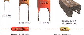
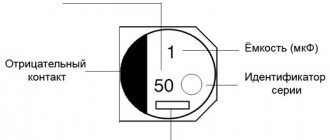
The capacitance value of the capacitor is indicated on the case in fractional farads or using a color code. But over time, components can lose their qualities, so for some critical cases the consequences may be unacceptable. There are other circumstances that require measurements. For example, the need to know the total capacity of a circuit or piece of electrical equipment. There are no devices that directly read the capacitance, but the value can be calculated manually or by processors integrated into the measuring devices.
To detect the actual capacitance, an oscilloscope is often used as a means of measuring the time constant (t). This value indicates the time in seconds during which the capacitor is charged by 63%, and is equal to the product of the circuit resistance in ohms and the circuit capacitance in farads: t = RC. An oscilloscope makes it easy to determine the time constant and makes it possible to use calculations to find the required capacitance.
There are also many models of amateur and professional electronic measuring equipment equipped with functions for testing capacitors. Many digital multimeters have the ability to determine capacitance. These devices are capable of charging and discharging a capacitor in a controlled manner with a known current and, by analyzing the increase in the resulting voltage, produce a fairly accurate result. The only drawback of most of these devices is the relatively narrow range of measured values.
You might be interested in this Symbol of radio components on the diagram and their name
More complex and specialized tools are bridge meters, which test capacitors in a bridge circuit. This indirect measurement method provides high accuracy. Modern devices of this type are equipped with digital displays and the ability to be used automatically in a production environment, they can be interfaced with computers and export readings for external monitoring.
Distance between plates
The capacitance of a capacitor is inversely proportional to the distance between the plates. In order to explain the nature of the influence of this factor, it is necessary to recall the mechanics of the interaction of charges in space (electrostatics).
If the capacitor is not in an electrical circuit, then the charged particles located on its plates are influenced by two forces. The first is the repulsive force between like charges of neighboring particles on the same plate. The second is the force of attraction of opposite charges between particles located on opposite plates. It turns out that the closer the plates are to each other, the greater the total force of attraction between charges with the opposite sign, and the more charge can be placed on one plate.
Methods of connecting elements
Capacitor Capacitance: Unit of Measurement
Mounting the product on the board can be vertical or horizontal. When using several products, they can be connected to each other in different ways.
Parallel connection
To organize it, you need to connect a group of parts to an electrical circuit so that the plates of all parts are connected directly to the switching points. Since all components receive charge from the same current source, they will have the same potential difference. But since the charge accumulates on each product separately, the amount of electricity on the group can be expressed as the sum of the quantities on its parts. This is also true for capacitive data - the value for the configuration is equal to the sum of the values of each unit. Therefore, such a group can be considered equal to one capacitor, the capacitive parameter of which is equal to the sum of those for all parts.
Parallel connection
Serial connection
This scheme involves connecting devices one after another, when only the two outermost products are connected to the connection points in the circuit. The amount of electricity for each part will be the same. In this case, the less capacitive the device, the higher the voltage value will be observed on it.
Important! The capacitance value of such a system will be even less than that of a device with the lowest value. The relationship looks like this: 1/C = 1/C1 + 1/C2 + 1/C3 + ... Based on it, we can directly derive formula C. For two elements: C = C1*C2 / C1+C2.
Serial connection
Mixed compound
Such a complex structure contains fragments with the above two types of connections. To calculate the total capacity, the circuit is divided into simple blocks, consisting only of parts connected in one way. Find equivalent values for each block and then draw the diagram again in a simplified form. Calculate data for the resulting system.
To be able to select a suitable capacitor set, you need to be able to find out the capacitance data. It is also important to know how the indicator is calculated for a configuration of several parts connected to each other in one way or another.
Relative dielectric constant
An equally significant factor influencing the capacitance of a capacitor is the property of the material between the plates as the relative dielectric constant ɛ. This is a dimensionless physical quantity that shows how many times the force of interaction between two free charges in a dielectric is less than in a vacuum.
Materials with a higher dielectric constant allow for greater capacitance. This is explained by the polarization effect - the displacement of the electrons of the dielectric atoms towards the positively charged capacitor plate.
Polarization creates an internal electric field in the dielectric, which weakens the overall potential (voltage) difference of the capacitor. Voltage U prevents the flow of charge Q to the capacitor. Therefore, lowering the voltage helps place more electrical charge on the capacitor.
Below are examples of dielectric constant values for some insulating materials used in capacitors.
- Air – 1.0005
- Paper – from 2.5 to 3.5
- Glass – from 3 to 10
- Mica – from 5 to 7
- Metal oxide powders – from 6 to 20
Capacity and energy of a capacitor.
The most important characteristic is the electrical capacitance of the capacitor. This is a physical quantity that is defined as the ratio of the charge of the capacitor q of one of the conductors to the potential difference between the conductors:
C = frac{q}{Deltavarphi} = frac{q}{U}
The capacitance of a capacitor is measured in Farads, but 1 F is quite large, so capacitance is most often measured in microfarads (µF), nanofarads (nF) and picofarads (pF). And since we have already derived the formula for calculating the voltage, let's express the voltage across the capacitor as follows:
It might be interesting➡ DC power supply
U = Ed = frac{qd}{varepsilon_0thinspacevarepsilon S}
Here we have d is the distance between the plates of the capacitor, and q is the charge of the capacitor. Let's substitute this formula into the expression for capacity:
C = frac{qvarepsilon_0thinspacevarepsilon S}{qd} = frac{varepsilon_0thinspacevarepsilon S}{d}
If we use air as a dielectric, then in all formulas we can substitute varepsilon = 1.
The following expressions are valid for the stored energy of a capacitor:
W = frac{CU^2}{2} = frac{qU}{2} = frac{q^2}{2C}
In addition to capacitance, capacitors are characterized by another parameter, namely the amount of voltage that its dielectric can withstand. When the voltage is too high, the dielectric's electrons are stripped from the atoms, and the dielectric begins to conduct current. This phenomenon is called capacitor breakdown, and as a result, the plates become short-circuited to each other. Actually, the characteristic that is often used when working with capacitors is not the breakdown voltage, but the operating voltage. This is a voltage value at which the capacitor can operate indefinitely for a long time, and breakdown will not occur.
So, today we looked at the basic properties of capacitors, their structure and characteristics! So this ends the article, and in the next one we will discuss various connection options and markings. Do not miss!
Rated voltage
The second most important characteristic after capacitance is the maximum rated voltage of the capacitor. This parameter indicates the maximum voltage that the capacitor can withstand. Exceeding this value leads to “punching” of the insulator between the plates and a short circuit. The rated voltage depends on the insulator material and its thickness (the distance between the plates).
It should be noted that when working with alternating voltage, it is the peak value (the highest instantaneous voltage value per period) that needs to be taken into account. For example, if the effective voltage of the power supply is 50V, then its peak value will be over 70V. Accordingly, it is necessary to use a capacitor with a rated voltage greater than 70V. However, in practice, it is recommended to use a capacitor with a voltage rating of at least twice the maximum possible voltage that will be applied to it.
Supercapacitor idea
Electricity is an extremely versatile form of energy , but has one drawback - it is difficult to accumulate quickly. Chemical batteries can store large amounts of energy but require several hours to fully charge. Capacitors do not have this disadvantage - they can be charged almost instantly. But their capacity does not allow storing large amounts of energy, so the idea of a supercapacitor, combining the best qualities of chemical and electrostatic electricity storage devices, looks very tempting.
Despite the functional similarity, batteries and capacitors are designed completely differently. Galvanic cells work on the principle of releasing electrical energy during a chemical reaction of substances within them. When the supply of active reagents is depleted, they stop generating a potential difference and for a new cycle they require the initiation of reverse chemical reactions by current to restore the active substances. The main disadvantages of batteries compared to capacitors:
- short life cycle;
- low power density;
- narrow range of charging and discharging temperatures;
- inability to quickly give up all energy reserves.
However, conventional capacitors are not used as active voltage sources due to their low capacitance. Theoretical and practical supercapacitors (ultracapacitors) differ from conventional ones in their extremely high capacity with a high stored energy density, which allows them to be considered as an alternative to chemical elements.
The largest commercial devices have capacities of up to several thousand farads, but their capabilities are still not comparable to batteries, so such devices are used to store charges for a relatively short period of time. They have found widespread use as the electrical equivalent of mechanical flywheels to smooth out the voltage of power supplies, for example in wind turbines or regenerative braking systems in electric vehicles.
The first ultracapacitors appeared in the middle of the last century and had not very impressive capacities. Since then, progress in improving materials has led to the thinning of the dielectric layer to a single molecule, which has made it possible to create devices with outstanding characteristics. The further development of the nanoindustry became the basis for fundamental changes in electricity storage. Perhaps, in the near future, environmentally hazardous and capricious chemical batteries will be replaced by supercapacitors based on molecularly structured plates and a dielectric layer.
