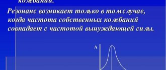
In general physical concepts, resonance conditions arise when the frequency of external influences coincides with the internal parameters of the system. A good example is the swing of a pendulum. With the correct selection of movements, weak force significantly increases the amplitude of oscillations. A similar result can be obtained in electrical circuits that are composed of components with reactive characteristics.
Definition of resonance
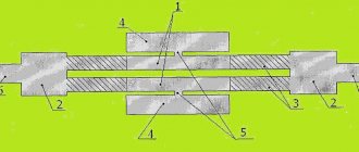
Using voltage resonance to transmit a radio signal
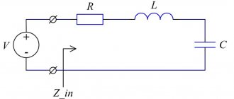
This type of oscillating circuit is created from a series combination of three basic components: resistor, capacitor, inductance. A suitable condition for resonance is zero circuit resistance (complex). To solve such a problem, you should study the basic formulas.
Complex resistance Rк=R+j(wL-1/wC). A fixed resistor (R) does not depend on frequency (w). This means that you will have to operate with inductive and capacitive elements. The resonance effect is obtained at (wL-1/wC)=0. To calculate the required values, use the following calculations:
- Lп=1/w2*C;
- Sp=1/w2*L;
- Wп=1/√L*C.
From the given data it is clear that you can adjust any of the parameters while maintaining the other two. In practical circuit design, it is more convenient to work with frequency, so we will consider in more detail the use of this option.
Sequential circuit with graphs
The figures show the conditions for the occurrence of voltage resonance. At the point designated w0, equality of the inductive and capacitive components at a certain frequency is observed. The slight shift to the left along the axis is due to the resistive component of the circuit.
The voltage on the capacitor (Uc) at the resonance frequency (W0) is equal to the characteristic impedance of the oscillatory circuit (p=√L/C). A similar potential difference will occur at the coil terminals at frequency W0. This feature explains the special name of the process – “stress resonance”. The following definitions are also used in electrical calculations:
- Quality factor – Q=p/R;
- Attenuation – 1/Q.
The noted properties are used in radio receiving and transmitting equipment. Isolating a specific range by the circuit allows you to tune the station to a specific frequency with an error determined by the circuit parameters. To control selectivity, the signal amplitude is estimated relative to the resonant frequency. The level of deviation of 3 dB in both directions (0.7 from the maximum) is called the passband.
Amplitude-frequency response (AFC) and bandwidth
Examples of practical application
A classic example of the use of resonance of oscillatory circuits is tuning a radio receiver to the frequency of the corresponding radio station. A capacitor with adjustable capacity is used as a working element of the tuning unit. Rotating the tuning knob changes the capacitance of the capacitor, and therefore the resonant frequency of the circuit.
When the resonant frequency coincides with the operating frequency of a radio station, a voltage resonance occurs, as a result of which the amplitude of oscillations of the frequency received by the radio receiver sharply increases. Special filters separate these vibrations from radio frequency carriers, and amplifiers amplify the received signals. Sounds generated by the radio station's transmitter appear in the speaker.
Oscillatory circuits, built on the principle of series connection of LC elements, are used in power circuits of high-resistance loads that consume high-voltage currents. The same devices are used in bandpass filters.
Series resonance is used at low network voltages. In this case, the reactive energy of the transformer windings connected in series is used.
Capacitors and various inductors are included in the design of almost all analog devices. They are used to configure filters or to control currents in individual nodes.
Inductors
It is important to know that resonant circuits do not increase the amount of electrical energy in the circuits. They can only increase voltages, sometimes to dangerous levels. Direct current does not cause resonance phenomena.
Along with the beneficial properties of resonance phenomena, in practical electrical engineering situations often arise when voltage resonance is harmful. This is mainly due to an undesirable increase in current parameters in sections of the circuits. An example is dangerous resonance phenomena in cable lines without load, which can lead to insulation breakdowns. To prevent this from happening, ballast load elements are installed at the end sections of such lines.
Natural frequency of the resonant circuit
Resistor power
The capacitance of the capacitor (C) together with the inductance of the coil (L) determines the natural frequency of the circuit (Wc). For approximate calculations, use the formula Wc=1/√L*C. In this case, we are talking about ideal conditions when losses are neglected due to minimal values.
To increase accuracy, the attenuation coefficient (Kz) is used. Taking this factor into account, the following relationship between natural and resonant frequencies can be given:
Wo=√Wc2-2*Кз2.
Helmholtz resonator
Humanity has known the amazing properties of empty vessels for a long time. Ancient architects used knowledge of sound resonance when building a theater: they placed bronze vessels in the walls to make the voices of the actors sound louder. Helmholtz resonators are widely used in acoustics. Helmholtz is a German scientist who substantiated the theory of hearing from a physical point of view. Using a set of resonators named after him, complex sounds can be analyzed based on the frequency of the wave's oscillations.
How does a resonator work? It is a spherical or bottle-shaped vessel with a narrow neck. The whole secret lies in the sound resonance of the vibrations of the air that is inside. The sound wave is complex. It consists of many vibrations. But each of the resonators responds best to the frequency that is equal to its own, that is, the frequency of vibration of the air enclosed in the cavity. What does it depend on?
If the resonator is shorter than the sound wavelength, then its operating principle is the same as that of a spring pendulum. The air in the narrow neck moves much faster than in the resonator itself. It is the vibrations in the neck of the vessel that play the main role. It turns out that the kinetic energy is concentrated mainly in this bottleneck. Elastic energy is carried by the air mass located inside the resonator.
There is much less air in the neck than inside, so the change in its volume during oscillations is usually neglected. It is conventionally believed that this entire mass moves as a single whole, like an air plug, and the volume of air inside the resonator changes greatly. It turns out that the air inside works like a spring in an oscillatory system. Its influx blocks the path of other air into the vessel, and the outflow lowers the pressure and prevents the release of air from the inside. When the air plug goes down, it compresses the nearby layer of air inside the resonator, i.e., increases its density. As a result, the growing pressure sets in motion the next layer of air, then another, etc. Thus, the compression spreads across the layers, transmits its momentum, and a sound wave arises.
It is now clear that the cause of the creepy voices in the apartment building was sound resonance. The howling of the wind and other noises from the street are disordered harmonic vibrations of different frequencies. They are called pure tones. When passing through the wall, all frequencies except resonant ones weakened. Resonant frequencies are those that coincide with the frequencies of the air in empty vessels. Moreover, they could even intensify. The policemen panicked because they heard sounds unusual for humans and living beings. The fact is that our speech sounds at a frequency much higher than 100 hertz, and the “brownie” made unusually low sounds.
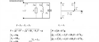
Current resonance, parallel resonance
In electrical engineering, a parallel rather than series connection of a capacitor and a coil is often used.
Something to remember! In such a situation, the reactive elements are considered according to a modified circuit. Instead of resistances, they operate with the sum of conductivities.
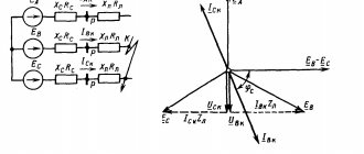
Electrical parameters and components, vector diagrams of voltages and currents
In this example, we will consider the refined parameters. The value (I) is determined by the sum of the currents that pass through the inductive and capacitive sections of the circuit. In both situations, the frequency ( w ) has a certain meaning:
- IL=E/(RL+Кз*w*L);
- Ic=E/(Rc+(1/Кз*w*С).
The diagrams clearly demonstrate characteristic changes in physical parameters when the circuit operates in three typical modes. Figure a) shows the capacitive version. It is assumed that w*L is greater than 1/w*С. In this case, the minimum value of RL can be neglected, which somewhat simplifies the above formula for calculating the current. It will lag behind the voltage vector by an angle ϕL. The second figure shows the opposite situation, when IL is greater than Ic.
For resonant conditions, the phases must coincide. This is shown by the vectors in Figure c). This situation will happen if w*L is equal to 1/ w*C. In this case, there is an approximate equality of IL and Ic, which is defined in the second name of the phenomenon - “current resonance”.
Description of the phenomenon
If in a certain electrical circuit (see Fig. 1) there are capacitive and inductive elements that have their own resonant frequencies, then when these frequencies coincide, the amplitude of the oscillations will increase sharply. That is, there is a sharp surge in stress on these elements. This can cause destruction of electrical circuit elements.
Rice. 1. Resonance in an electrical circuit
Let's look at this example to see what phenomena will occur when an alternating current generator is connected to the contacts of the circuit. Note that coils and capacitors have properties that can be compared to the analogue of a reactive resistor. In particular, a choke in an electrical circuit creates inductive reactance. The capacitor causes capacitance.
The inductive element causes a phase shift, characterized by a lag of the current from the voltage by ¼ of a period. Under the action of a capacitor, the current, on the contrary, leads the voltage by ¼ period.
In other words, the effect of inductance is opposite to the effect on the phase shift of capacitance. That is, inductors and capacitive elements influence the generator in different ways and adjust the phase relationships between electric current and voltage in their own way.
The total reactance of the elements we are considering is equal to the sum of the resistances of each of them. Taking into account the opposite actions, we can write: Xtot = XL - Xc, where XL = ωL is the inductive reactance, the expression Xc = 1/ωC is the capacitive reactance.
Figure 2 shows graphs of the dependence of the circuit impedance and the associated current on the reactance of the inductive element. Pay attention to how the total resistance decreases as the reactance RL decreases (graph b) and how the current increases (graph c).
Rice. 2. Graphs of the dependence of current parameters on the drop in reactance
Electrical circuits consisting of series-connected capacitors, passive resistors and inductors are called series resonant (oscillatory) circuits (see Fig. 2). There are also parallel circuits in which R, L, C elements are connected in parallel (Fig. 3).
Rice. 3. Series oscillatory circuit
Rice. 4. Parallel oscillatory circuit
In resonance mode, the power of the power source will be dissipated only through active resistances (including the active resistance of the coil). Resonant circuits are characterized by losses only of active power, which is spent to maintain the oscillatory process. Reactive power on LC elements is not consumed. The current in the resonant mode takes on the maximum value:
The value of Q is usually called the term “Q factor” of the circuit. This parameter shows how many times the voltage generated at the contacts of the reactive elements exceeds the input voltage U of the electrical network. To describe the ratio of output and input voltages, the coefficient K is often used. At resonance:
K = Uout / Uin = UC0 / U = Q
Based on the phenomena described above, we formulate the definition of resonant voltage: “If the total voltage drop across the capacitive-inductive elements is zero and the current amplitude is maximum, then this special state of the system is called voltage resonance.” For a better understanding of the phenomenon, let us rephrase the definition a little: voltage resonance is a state when the voltage on the CL circuit is greater than at the input of the electrical circuit.
The described phenomenon is quite common in electrical engineering. Sometimes they fight it, and sometimes they specially create conditions for the formation of resonance. The main characteristics of any resonant circuit are the quality factor and frequency parameters [1].
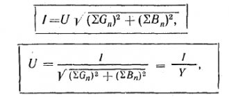
If XL = Xc, the equality is true: ωL = 1/ωC, from here we obtain:
If ω = ω0 – voltage resonance occurs. The frequencies coincide when the inductive reactance is equal to the capacitive reactance of the capacitor. In such cases, only active resistance R will act in the circuit. The presence of reactive elements in the circuit leads to an increase in the total resistance of the circuit (Z):
where R is the total active resistance.
Considering that, according to Ohm's law, U = I/Z, it can be argued that the total voltage in the circuit depends, among other things, on the terms of the inductive and capacitive reactance.
If in the circuit under consideration (Fig. 1) there was no active resistance R, then the value of the total resistance Z would tend to 0. Consequently, the voltage on the reactive elements increases to a critical level.
It will be interesting➡Features of current resonance
Since XL and Xc depend on the frequency of the input voltage, for resonance to occur, you must select the appropriate network frequency, or change the parameters of the coil or capacitor until the resonant frequencies coincide. Any violation of the resonance conditions immediately leads to the system exiting the resonant mode with a subsequent voltage drop.
Resonance phenomena occur only if the following conditions are present:
- The presence of minimal active resistance in a section of the electrical circuit.
- Equality of reactances arising on the LC chain.
- Coincidence of the input frequency of the power supply with the resonant frequency of the oscillatory circuit.
When there is resonance in the circuit, the voltages on its elements can increase by an order of magnitude or more.
Resonance in distributed oscillatory systems, nonlinear processes
A common concept for all phenomena in this category can be called an effective connection with the environment. In mechanical systems, the amplitude of the phase characteristics of the process is influenced by a certain position in space. In the oscillatory circuit of a radio receiver, in addition to its own attenuation, it is necessary to take into account the real electromagnetic background. Under certain conditions with a high quality factor, the formation of standing waves is permissible.
You should understand! The result of the impact largely depends on the coincidence in phase and frequency.
If the spring is created with a different coil density distribution, the standard formulas do not apply. Standard calculations assume uniform elasticity and deformation of each part. To clarify nonlinearity, correction factors and complex multi-stage calculation schemes are used.
Similar features are taken into account when using diodes or other radio components with variable amplitude-frequency characteristics. If the inductor is wound on a core made of ferromagnetic material, the nonlinearity of the output parameters will also have to be taken into account. It cannot be described by the elementary equation of Ohm's law.
In nonlinear circuits with a certain spectral distribution of external influences, harmonic oscillations are present. In addition to the coincidence of frequencies, their amplitude is important. Depending on the settings, they are capable of performing useful and harmful functions. Certain conditions cause the underlying waveform to become distorted.
"Singing" stone
Not far from Baku, the capital of Azerbaijan, there is a desert with the famous “singing” stone. It is so famous that it received the name “Stone Tambourine”. This amazing block has the property that if you hit it with a stone, the sound will be as loud and clear as a bell. How does physics explain this example of sound resonance?
The impact leads to short-term deformation - immediately sound waves run in all directions from the point of collision. The size of the stone does not affect the speed of their divergence. However, the wave can propagate freely only in unlimited space. But we know that stone and air have boundaries (where they touch).
Resonance in linear systems with one degree of freedom
The considered serial and parallel electrical circuits can be included in this group. A mechanical example is a spring with a load that can only move in a vertical straight line. Gusts of wind, vibrations, and other “parasitic” external influences are excluded. In such conditions, standard formulas for linear systems can be used.
The quality factor noted above is the determining factor for frequency selectivity. Narrowing the width of the resonant range helps improve the performance of receiving and transmitting devices. In addition to economical consumption of electricity, with proper design of the circuit, noise immunity is significantly improved.
Mysterious house
In “Stories about Old Moscow” by A. Vyurkov, a house is described that sounds like a scary voice. The main character of the work, Ivan Pavlovich, decided to get rich by fraud. He hired a team of masons to build him an apartment building and did not pay them the full amount promised. Soon the tenants began to leave the hotel one after another, because they were frightened by the evil spirits that howled in an inhuman voice.
Ivan Pavlovich was left without money and without tenants. He had nothing to pay the interest on the loan, so his property and himself were seized. As time passed, one of the contractors revealed to Ivan Pavlovich the secret of the mystical house. It turns out that the deceived workers decided to take revenge: they walled up empty bottles in the wall, which sounded with every gust of wind, scaring the guests.
Parallel resonance with an EMF source
The quality factor for a parallel circuit is calculated using the formula Q=R√C/L. If the frequencies (source and circuit) are equal, the resistance in the individual branches does not differ. Identical current values are created by compensated reactive parameters of the capacitor and coil.
When the frequency deviates from the resonant value to the lower (upper) range, the resistance acquires a capacitive (inductive) character, respectively. In a normal operating cycle, energy exchange occurs between the reactive elements of the circuit. This mode is characterized by a Q times increase in the current passing through the internal circuit compared to that coming from the EMF source. Ideal conditions, when the quality factor tends to an infinite value, are impossible. Direct and parasitic losses in circuits limit the growth of the resonant current strength.
Mechanical oscillations of a pendulum
The simplest model that can clearly show oscillations is a simple pendulum, or rather a mathematical pendulum. Oscillations are divided into free and forced. Initially, the energy acting on the pendulum provides free oscillations in the body without the presence of an external source of variable impact energy. This energy can be either kinetic or potential.
Here it does not matter how strongly or not the pendulum itself swings - the time spent traveling its path in the forward and reverse directions remains unchanged. To avoid misunderstandings with the damping of oscillations due to friction with air, it is worth highlighting that for free oscillations the conditions for the pendulum to return to the point of equilibrium and the absence of friction must be met.
But the frequency, in turn, directly depends on the length of the pendulum thread. The shorter the thread, the higher the frequency and vice versa.
The natural frequency of a body that arises under the influence of an initially applied force is called the resonant frequency.
All bodies that are characterized by vibrations perform them with a given frequency. To maintain undamped vibrations in the body, it is necessary to provide constant periodic energy “feeding”. This is achieved by exposure to a simultaneous vibration of the body of a constant force with a certain period. Thus, the vibrations that arise in the body under the influence of a periodic force from the outside are called forced.
At some point in the external influences, a sharp jump in amplitude occurs. This effect occurs if the periods of internal vibrations of the body coincide with the periods of external force and is called resonance. For resonance to occur, very small values of external sources of influence are sufficient, but with the obligatory condition of repetition in time. Naturally, when making actual calculations under terrestrial conditions, one should not forget about the action of friction forces and air resistance on the surface of the body.
Series resonance with current source
Measuring resistance in a circuit with reactive elements connected in series will help detect resonance at a certain frequency. In this case, a current source is used for the experiment. At low (high) frequencies, the capacitive (inductive) characteristics of the circuit have a limiting effect. At the resonance frequency, the total reactance is minimal.
Electrical parameters in series circuit
The figures show the following dependences on frequency:
- A. general resistance;
- b. reactive components;
- V. current strength in resonant modes.
see also
Write answers to questions for self-test in the comments, we will check, or ask your own question on this topic.
Capacitance in a line with a constant current looks like an open circuit segment, induction is represented by a conductor. With alternating current, the reactive resistor analogue is represented by coils with condensation devices.
Reactance depends on the value of capacitance or inductance, as well as the frequency of the variable current.
Looking at the calculation of the reactive value, it becomes noticeable that having certain values of the inductive or capacitive element, their difference is equal to zero, and, as a result, the remainder will contain active resistance. This situation has some other nuances.
Resonance in real circuits
To study the described processes, it is necessary to assemble a circuit from the appropriate components. You will have to prepare a generator with a variable output signal frequency, an oscilloscope and other measuring instruments. To get reliable results without unnecessary difficulties, use specialized software.
Theory and practice
The left side of the figure shows the circuit and amplitude of the output signal when connected to the terminals of a parallel circuit capacitor. On the right is a screenshot of the measuring equipment. It is easy to verify the identity of the vibrations.
For your information. Using the software, dozens of experiments can be performed quickly and accurately in normal home conditions. This method greatly simplifies the creation of electrical circuits with optimal parameters.
Inductance and capacitance reactances
Inductance is the ability of a body to accumulate energy in a magnetic field. It is characterized by a phase lag between the current and the voltage. Typical inductive elements are chokes, coils, transformers, electric motors.
Capacitance refers to elements that accumulate energy using an electric field. Capacitive elements are characterized by a phase lag between voltage and current. Capacitive elements: capacitors, varicaps.
Their main properties are given; the nuances are not taken into account within the scope of this article.
In addition to the listed elements, others also have a certain inductance and capacitance, for example in electrical cables distributed along its length.
Resonance in linear oscillatory systems with several degrees of freedom
Such calculations will be needed when designing two series circuits with inductive coupling. In this case, the alternating oscillatory processes exert mutual influence. In fact, we are talking about a distributed system.
In addition to circuit design, in such situations the coupling coefficient (Kc) is studied separately. When working with a transformer, it is calculated by dividing the voltages on the primary (secondary) coil, respectively. It is necessary to take into account the reactive characteristics that prevail in the operating frequency range.
Having learned what resonance of voltages and currents is, you can independently implement various projects. Careful preliminary preparation is necessary to create a circuit with good performance parameters. They start with drawings and calculations. Theoretical research is complemented by the production of a prototype and practical tests. They speed up the preparation of design documentation and also carry out experiments using software. In the most difficult situations, they turn to experienced specialists.
How to use
Resonant currents are used today in some filter systems, radio engineering, electricity, radio stations, asynchronous motors, high-precision electrical welding installations, oscillating generator electrical circuits and high-frequency devices. Often they are used to reduce the generator load.
Note! The simplest circuit where they are observed is a parallel oscillatory circuit. Such circuits are used in modern industrial induction boiler equipment and improve efficiency indicators
Scope of application
Experience with tuning forks
An acoustic wave is like a swing: if you push it haphazardly, losing the rhythm, then it will not fly high
The importance of matching frequency (rhythm) can be easily seen in the experiment with two tuning forks. Let's take those that have the same frequency and place them quite close to each other
Let's hit the legs of the first one with a hammer - it will sound, and very soon it will make the other one sound. Why will this happen? The second instrument will be set in motion (swinged) by the sound wave. When the first one is silent, the second one will make a sound for some time. This is how sound resonance occurs. If we perform an experiment on tuning forks of different frequencies, we will see that they do not resonate.