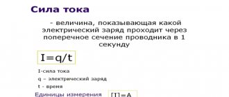
Definition Electric current is the directed movement of charged particles under the influence of an external electric field.
Conditions for the existence of electric current:
- the presence of charged particles;
- the presence of an electric field that is created by current sources.
Electric current carriers in various environments
| Wednesday | Electric current carriers |
| Metals | Free electrons |
| Electrolytes (substances that conduct current due to dissociation into ions) | Positive and negative ions |
| Gases | Ions and electrons |
| Semiconductors | Electrons and holes (an atom missing one electron) |
| Vacuum | Electrons |
What does Ohm's law sound like for a section of a circuit?
If we talk about the official formulation, then Ohm’s law can be stated as follows:
Current strength has a direct relationship with voltage and an inverse relationship with resistance. This statement is true for a section of a circuit with some specific and stable resistance.
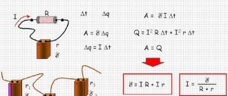
The formula for this dependence is in the figure. Here I is the current, U is the voltage, R is the resistance.
Ohm's law formula
- The higher the voltage, the higher the current.
- The greater the resistance, the less current.
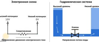
It is not so easy to imagine the meaning of this expression. After all, electricity cannot be seen. We only know approximately what it is. Let's try to understand the meaning of this law with the help of analogies.
Nonlinear elements and circuits
Ohm's law is not a fundamental law of nature and can be applied in limited cases, for example, for most conductors. It cannot be used to calculate voltage and current in semiconductor or vacuum devices, where this dependence is not proportional and can only be determined using the current-voltage characteristic (volt-ampere characteristic). This category of elements includes all semiconductor devices (diodes, transistors, zener diodes, thyristors, varicaps, etc.) and vacuum tubes. Such elements and the circuits in which they are used are called nonlinear.
Let's understand what current and resistance are
Let's start with the concept of electric current. In short, electric current as applied to metals is the directed movement of electrons - negatively charged particles. They are usually presented in the form of small circles. In a calm state, they move chaotically, constantly changing their direction. Under certain conditions—the appearance of a potential difference—these particles begin to move in a certain direction. This movement is electric current.
To make it clearer, we can compare electrons to water spilled on some plane. While the plane is motionless, the water does not move. But as soon as the tilt appeared (a potential difference arose), the water began to move. It's about the same with electrons.
This is how you can imagine electric current
Now we need to understand what resistance is and why they have an inverse relationship with current strength: the higher the resistance, the lower the current. As you know, electrons move along a conductor. Usually these are metal wires, since metals have a good ability to conduct electric current. We know that metal has a dense crystal lattice: many particles that are located closely and interconnected. Electrons, making their way between metal atoms, collide with them, which complicates their movement. This helps illustrate the resistance that a conductor provides. Now it becomes clear why the higher the resistance, the lower the current strength - the more particles, the more difficult it is for electrons to overcome the path; they do it more slowly. This seems to have been sorted out.
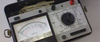
If you want to check this dependence experimentally, find a variable resistor, connect the resistor - ammeter - current source (battery) in series. It is also advisable to insert a switch into the circuit - a regular toggle switch.
Circuit for checking the dependence of current on resistance
By turning the resistor knob you change the resistance. At the same time, the readings on the ammeter, which measures the current, also change. Moreover, the greater the resistance, the less the needle deviates - the less current. The lower the resistance, the more the needle deviates - the greater the current.
Instead of a dial gauge, you can use a digital multimeter in DC measurement mode. In this case, the readings are monitored on the liquid crystal digital display.
The dependence of current on resistance is almost linear, that is, it is reflected in the graph as an almost straight line. Why almost? This needs to be discussed separately, but that’s another story.
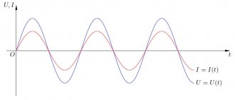
Use for AC
As is known, in an alternating current circuit there is both active and reactive resistance. The first of them coincides with how this quantity was understood in the time of Georg Ohm. However, inductive and capacitive reactance also inhibit the movement of electrons. In this case, Ohm's law for alternating current applies.
To use this law in such circuits, instead of ohmic resistance, total resistance should be considered, which takes into account the total effect of the active and reactive components of the resistance.
In the presented circuit, the total resistance is denoted as Z. Ohmic, inductive and capacitive - R, XL and XC, respectively. Ohm's law for an alternating current circuit takes into account all these variations. The calculation formula implies that the addition of resistances occurs according to the vector rule.
To determine all resistances, a right triangle is used, one leg of which expresses the active resistance, and the second - the reactive one. The latter is equal to the difference between inductive and capacitive reactances. The determination of the total is carried out according to the Pythagorean theorem, according to which the length of the hypotenuse is equal to the square root of the sum of the squares of the legs.
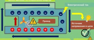
Talking about tension
It is equally important to understand what tension is. Let's start with an analogy right away and use water again. Let there be water in the funnel. It leaks through a narrow neck, which creates resistance. If you imagine that a load is placed on the water, the movement of the water will accelerate. This load is tension. And now it is also clear why the higher the voltage, the stronger the current - the stronger the pressure, the faster the water will move. That is, the relationship is direct: more voltage - more current. And it is precisely this situation that is reflected by Ohm’s law - “pressure” is in the numerator (at the top of the fraction).
You can try to imagine the tension in a different way. There are still the same electrons that have accumulated at one edge of the power source. There are few of them on the second edge. Since each of the electrons has some kind of charge, where there are many of them, the total charge is greater, where there are few, less. The difference between the charges is the voltage. This is also easy to imagine. From an electrical point of view, this is a more correct representation, although not accurate.
There are many funny pictures on the topic of Ohm's law that allow you to understand all these phenomena a little better. One of them is in front of you and illustrates how current depends on voltage and resistance. Look what happens: the resistance tries to reduce the current (inverse relationship), and with increasing voltage it increases (direct relationship). This is Ohm's law, but expressed in simple words.
Thanks to the picture, it is easy to understand the dependence of current on voltage and resistance
If you want to be convinced of this dependence, you also need to create a simple chain. But you will need either a regulated power source or several batteries that produce different voltages. Or you can connect several batteries in series - that’s also an option. But you need to change/solder the batteries when the circuit is open (the toggle switch is off).
This circuit uses two measuring instruments: an ammeter is connected in series with the load (resistor in the diagram below), a voltmeter in parallel with the load.
Diagram to illustrate Ohm's law
Since other circuit parameters remain normal, as the voltage increases we will see an increase in current. The more voltage we apply, the more the voltmeter and ammeter needles deviate. If you set out to build a graph, it will be in the form of a straight line. If you install another resistance, the graph will also be in the form of a straight line, but its angle of inclination will change.
What changes for a full chain
In the situation above, only a certain section of the circuit with some fixed resistance is considered. We assume that under certain conditions the electrons will begin to move. The reason for this movement is the same load in the picture. In real conditions, this is a current source. This could be a battery, a DC generator, a connected power supply cord, etc. When a power source is connected to a conductor, current begins to flow through it. We also know and observe this when we turn on a lamp, charge a mobile phone, etc.
The complete circuit includes a power supply
A section of the circuit has some kind of resistance. It's clear. But the power supply also has resistance. It is usually denoted with a small letter r. Since the current runs in a circle, it has to overcome the resistance of the wire and the resistance of the current source. This total resistance of the circuit and the power source is called impedance. They also say that this is complex resistance. In Ohm's formula for a complete circuit it is represented by a sum. The denominator is the sum of the circuit resistance and the internal resistance of the current source (R + r).
Everyone probably understands that it is the current source that creates the necessary conditions for the movement of electrons. All thanks to the fact that it has EMF - electromotive force. This value is usually denoted E. The greater this force, the greater the current. This also seems understandable. Therefore, the designation of EMF - the Latin letter E - is placed in the numerator. Thus, the formulation of Ohm's law for a complete circuit sounds like this:
The current strength is directly proportional to the emf of the current source and inversely proportional to the sum of the circuit resistance and the internal resistance of the current source.
It doesn’t seem too difficult, but you can try something even simpler:
- The higher the EMF of the current source, the greater the current.
- The greater the total resistance, the less current.
Inductive reactance
Let a section of the circuit have only inductance (Fig. 3). We will assume $I>0$ if the current is directed from $a$ to $b$.
Figure 3.
If a current flows in the coil, then a self-inductive emf appears in the inductance, therefore, Ohm’s law will take the form:
By condition $R=0. The mathcal E$ of self-induction can be expressed as:
From expressions (8), (9) it follows that:
The voltage amplitude in this case is equal to:
where $X_L is $inductive reactance (apparent inductive resistance).
How to find resistance, voltage
Knowing the formula of Ohm's law for a section of a circuit, we can calculate the voltage and resistance. Voltage is found as the product of current and resistance.
Formula for voltage and resistance according to Ohm's law
Resistance can be found by dividing voltage by current. It's really not difficult. If we know that a certain voltage was applied to a section of the circuit and we know what the current was, we can calculate the resistance. To do this, divide the voltage by the current. We get exactly the resistance value of this piece of circuit.
On the other hand, if we know the resistance and the current that should be there, we can calculate the voltage. You just need to multiply the current and resistance. This will give the voltage that must be applied to this section of the circuit to obtain the required current.
Electrical circuit efficiency
It's not hard to see why a resistor is called a payload. Imagine it's a light bulb. The heat generated by a light bulb is beneficial
, since thanks to this warmth the light bulb fulfills its purpose - giving light.
Let us denote the amount of heat released by the payload during time .
If the current in the circuit is equal to , then
A certain amount of heat is also released at the current source:
The total amount of heat released in the circuit is equal to:
Electrical circuit efficiency
is the ratio of useful heat to total heat:
The efficiency of the circuit is equal to unity only if the current source is ideal.
Parallel and serial connection
In electrics, elements are connected either in series - one after the other, or in parallel - this is when several inputs are connected to one point, and outputs from the same elements are connected to another.
Ohm's law for parallel and series connections
Serial connection
How does Ohm's law work for these cases? With a series connection, the current flowing through the chain of elements will be the same. The voltage of a section of a circuit with elements connected in series is calculated as the sum of the voltages in each section. How can this be explained? The flow of current through an element is the transfer of part of the charge from one part to another. That is, this is a certain job. The amount of this work is tension. This is the physical meaning of tension. If this is clear, let's move on.
Serial connection and parameters of this section of the circuit
With a series connection, the charge has to be transferred through each element in turn. And on each element this is a certain “amount” of work. And to find the amount of work on the entire section of the chain, you need to add up the work on each element. So it turns out that the total voltage is the sum of the voltages on each of the elements.
In the same way - using addition - the total resistance of a circuit section is found. How can you imagine this? Current flowing through a chain of elements consistently overcomes all resistance. One after another. That is, to find the resistance that he overcame, you need to add up the resistances. Like that. The mathematical derivation is more complex, but it is easier to understand the mechanism of action of this law.
Parallel connection
A parallel connection is when the beginnings of the conductors/elements converge at one point, and their ends are connected at another. We will try to explain the laws that are valid for compounds of this type. Let's start with the current. A current of some magnitude is supplied to the point of connection of the elements. It separates, flowing through all conductors. From here we conclude that the total current in the section is equal to the sum of the current on each of the elements: I = I1 + I2 + I3.
Now regarding the voltage. If voltage is the work done to move a charge, then the work required to move one charge will be the same on any element. That is, the voltage on each parallel-connected element will be the same. U = U1=U2=U3. It’s not as fun and visual as in the case of explaining Ohm’s law for a section of a circuit, but you can understand it.
Laws for parallel connection
For resistance, everything is a little more complicated. Let's introduce the concept of conductivity. This is a characteristic that shows how easy or difficult it is for a charge to pass through this conductor. It is clear that the lower the resistance, the easier it will be for current to pass. Therefore, conductivity - G - is calculated as the reciprocal of resistance. In the formula it looks like this: G = 1/R.
Why did we talk about conductivity? Because the total conductivity of a section with a parallel connection of elements is equal to the sum of the conductivity for each of the sections. G = G1 + G2 + G3 - easy to understand. How easy it is for current to cross this node of parallel elements depends on the conductivity of each element. So it turns out that they need to be folded.
Now we can move on to resistance. Since conductivity is the reciprocal of resistance, we can obtain the following formula: 1/R = 1/R1 + 1/R2 + 1/R3.
What does parallel and serial connection give us?
Theoretical knowledge is good, but how to apply it in practice? Elements of any type can be connected in parallel or in series. But we considered only the simplest formulas describing linear elements. Linear elements are resistances, which are also called “resistors”. So here's how you can use what you've learned:
- If there is no large resistor available, but there are several smaller ones, the required resistance can be obtained by connecting several resistors in series. As you can see, this is a useful technique.
- To extend the life of the batteries, they can be connected in parallel. In this case, according to Ohm’s law, the voltage will remain the same (you can verify this by measuring the voltage with a multimeter). And the “lifetime” of a dual battery will be significantly longer than that of two elements that replace each other. Just note: only power supplies with the same potential can be connected in parallel. That is, you cannot connect dead and new batteries. If you do connect, the battery that has a higher charge will tend to charge the less charged one. As a result, their total charge will drop to a low value.
Practical application of Ohm's law: you can create power supplies with the desired voltage and current
In general, these are the most common uses for these compounds.
Scope of application
Ohm's law is not a basic law in physics, it is just a convenient dependence of some values on others, which is suitable in almost any practical situation. Therefore, it will be easier to list situations when the law may not work:
- If there is inertia of charge carriers, for example in some high-frequency electric fields;
- In superconductors;
- If the wire heats up to such an extent that the current-voltage characteristic ceases to be linear. For example, in incandescent lamps;
- In vacuum and gas radio tubes;
- In diodes and transistors.
Interesting read: instructions on how to ring a transistor.