When a short circuit occurs, the constant current values undergo significant changes. At the very first instant, the so-called aperiodic component of the short-circuit current appears, which quickly fades away and takes on a zero value. This time interval when these changes are observed represents a transition period, defined in numerical terms. Until the emergency current condition is turned off, the electrical network operates in a steady-state short circuit mode.
Physical properties of the aperiodic component
A similar current state occurs at the moment of a short circuit. Its duration and characteristics may vary, depending on many factors. For example, if the motor has a damper winding, the aperiodic component of the short circuit current will be lower than if it is absent. First, a supertransient current arises, which at first becomes simply transient, and only then does it begin to fade.
During a two-phase circuit, sudden changes in current do not appear in the stator. In such situations, at idle, an aperiodic component appears, the parameters of which coincide with the initial value of the variable component. Since the short-circuit current inside the stator is single-phase, in some cases the appearance of an aperiodic component is completely eliminated. In asynchronous motors, this indicator is not taken into account, since these processes die out very quickly. It is not taken into account even when calculating short-circuit surge currents.
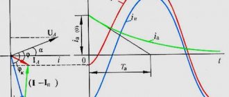
In general, the magnitude of these components will differ for each phase. Its initial parameters will depend on the moment the short circuit appears. On the graphs it represents a solid curved line, since all the initial amplitudes of the other components will be equal to it, but directed in the opposite direction.
The presence of an aperiodic component is established when the contacts diverge. To evaluate it, there is a special parameter, which is the relationship between it and the periodic amplitude at the moment the contacts open. The decay time is approximately 0.1-0.2 s and is accompanied by significant heat generation. Under the influence of high temperatures, current-carrying parts and the entire equipment as a whole heat up noticeably, despite such a short period of time.
Types, causes and consequences of short circuits
Definition 1
A short circuit is an electrical connection of two points of an electrical circuit that have different potentials that are not provided for by the design of the device.
The main causes of a short circuit are: malfunction of electrical equipment, exposed contacts, worn insulating material, overload of the electrical network, violation of the integrity of wires and cables, etc. A short circuit can occur in both electrical networks and electrical machines. The following types of short circuit are typical for electrical networks: single-phase, two-phase, three-phase, and two-phase to ground. Electrical machines are characterized by an interturn short circuit (short circuit of the stator or rotor turns or the turns of the transformer windings).
Are you an expert in this subject area? We invite you to become the author of the Directory Working Conditions
During a short circuit, the current strength increases repeatedly and sharply, which causes a large release of heat and melting of electrical wires, which contributes to ignition and the spread of fire. To prevent short circuits, current-limiting reactors, disconnecting equipment, step-down transformers and relay protection devices are installed.
Total current when a short circuit occurs
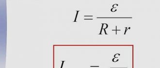
The aperiodic component itself cannot be considered, since it is one of the components of the short circuit current. The electrical network contains inductive resistances that prevent the current from changing instantly at the moment a short circuit occurs. The increase in load current does not occur spasmodically, but according to certain laws that require a transition period from normal to emergency values. Calculation and analytical work is greatly simplified when the short-circuit current during a transition is considered as two components - aperiodic and periodic.
The aperiodic part is a component of the current ia with a constant value. It appears immediately at the moment of short circuit and in the shortest possible time drops to zero.
The periodic part of the short-circuit current Iпm is called the initial part, since in time it appears at the very beginning of the process. This indicator is used to select the most suitable setting or check the sensitivity of relay protection. This current is also known as subtransient current, since it is determined using subtransient resistances introduced into the equivalent circuit. The periodic current is considered to be steady when the aperiodic part fades and the transient process itself ends.
Consequently, the total short circuit current will be the sum of both parts - aperiodic and periodic during the entire period of state transition. At a certain moment, the total current reaches its maximum value in the shortest possible time. This condition is known as short-circuit shock current, which is determined when checking the electrodynamic stability of installations and equipment.
The choice of initial or supertransient current for calculations determines the rapid decay of the aperiodic part, which occurs before the protection is triggered. In this case, the periodic component remains unchanged.
Electrical networks connected to generator sets or a power-limited power system are characterized by significant voltage changes when a fault occurs. In this regard, the currents, initial and steady, will not be equal to each other. In order to calculate relay protection, you can use the initial current indicators. In this case, the error will be insignificant in comparison with the steady-state current exposed to various factors. First of all, this is increased resistance at the damaged point, load currents and other parameters that are most often not taken into account when performing calculations.
How to calculate the aperiodic component
The initial value of the aperiodic part in modular terms is defined as the difference between the instantaneous indicator of the periodic part at the beginning of the short circuit and the current value immediately before the short circuit. That is, the aperiodic component with the maximum initial value will be equal to the amplitude parameters of the periodic part of the current when a short circuit occurs. This statement is determined by the formula: ia0 = √2Iп0, operating under the condition of a reduced active fraction of the resistance at the short-circuit point relative to the inductive component.
1. 2.
In addition, before the start of the circuit there should be no load at the design point, and the voltage of any phase by this time passes through the neutral conductor. If the listed requirements are not met, then the aperiodic part in the initial stage will reduce its performance in relation to the amplitude of the periodic component.
In order to calculate the aperiodic component of the short-circuit current at any arbitrary time, a substitution option is worked out in advance. According to the initial design scheme, all components are taken into account as active and inductive reactances. Accounting for synchronous generators and compensators, asynchronous and synchronous electric motors is carried out by transferring them to the category of inductive reactances with negative sequence. The resistance of the stator windings to direct current with the operating temperature of the established norm must be taken into account.
3.
When the initial calculation scheme contains only components connected in series, in this case the value of the aperiodic fraction at any time is determined by formula 1, in which Ta is a constant value that determines the decay time of this part. In turn, Ta can be calculated using formula 2, in which Xek and Rek will be the inductive and active components, and ωsync is the synchronous angular frequency of the mains voltage. If, in the calculations, it is necessary to take into account the value of the generator current immediately before the short circuit, then formula 3 is already used.
Calculation of short circuit currents
CHAPTER SEVEN
CALCULATION OF SHORT CIRCUIT CURRENTS
7.1. Short circuit in a symmetrical three-phase circuit of an industrial plant
The determination of short-circuit currents depends on the requirements for the accuracy of the results, on the initial data and the purpose of the calculation. In the general case, short-circuit currents are determined by transient processes in electrical circuits studied by the theoretical foundations of electrical engineering. The calculation of short-circuit currents in electrical networks of industrial enterprises is somewhat different from the calculations carried out in electrical networks and systems. This is explained by the possibility of not highlighting (not taking into account) turbo and hydrogenerators of power plants, recharge from several power sources, the operation of branched complex ring circuits, the properties of long-distance power lines, and actual transformation ratios.
To select devices and conductors, to determine the impact on supporting structures when calculating short-circuit currents, proceed from the following provisions. All sources involved in powering the point in question operate at rated load. Synchronous machines have automatic voltage regulators and high-speed excitation boosters. A short circuit occurs at a point in time at which the short circuit current has the greatest value. The electromotive forces of all power sources are in phase. The design voltage of each stage is taken to be 5% higher than the rated network voltage (average rated voltage), namely: 515; 340; 230; 154; 115; 37; 24; 18; 15.75; 13.8; 10.5; 6.3; 3.15; 0.69; 0.525; 0.4; 0.23; O.133 kV.
The influence on short-circuit currents of synchronous compensators, synchronous and asynchronous electric motors connected to this network is taken into account. The influence of asynchronous electric motors on short-circuit currents is not taken into account for a unit power of electric motors up to 100 kW, if the electric motors are remote from the short-circuit location by one transformation stage, as well as at any power, if they are separated from the short-circuit location by two or more transformation stages or if current can flow from them to the fault location only through those elements through which the main short-circuit current from the network passes and which have significant resistance (lines, transformers, etc.).
In electrical installations with voltages above 1 kV, the inductive resistance of electrical machines, power transformers and autotransformers, reactors, overhead and cable lines, and conductors are taken into account. Active resistance should be taken into account only for overhead lines with wires of small cross-sectional areas and steel wires, as well as for long cable networks of small cross-sections with high active resistance.
In electrical installations with voltages up to 1 kV, the inductive and active resistances of all elements of a short-circuited circuit are taken into account (transition contacts of devices, current coils, transition resistances, phase unbalance, etc.). It should be noted that the influence of the power system resistance on the results of calculating short-circuit currents on the side up to 1 kV is small. Therefore, in practical calculations, the resistance on the 6-10 kV side is often neglected, considering it equal to zero. In the case of supplying electrical networks with voltages up to 1 kV from step-down transformers, when calculating short-circuit currents, one should proceed from the condition that the voltage supplied to the transformer is constant and equal to its rated value.
The requirements for calculating short-circuit currents for relay protection and system automation are somewhat different from the calculation requirements for selecting devices and conductors. The requirements for the accuracy of calculations of short-circuit currents for the selection of grounding devices are low due to the low accuracy of methods for determining other parameters included in the calculation of grounding devices (for example, earth resistivity). Therefore, to select grounding devices, it is possible to determine the values of short-circuit currents using an approximate method.
The design diagram for determining short-circuit currents is a single-line diagram, which includes generators, compensators, synchronous and asynchronous electric motors that influence the short-circuit current, as well as elements of the power supply system (lines, transformers, reactors) connecting electricity sources to the fault location . When drawing up a design diagram for selecting electrical devices and conductors and determining short-circuit currents, one should proceed from the conditions of long-term operation provided for a given electrical installation. In this case, there is no need to take into account short-term modifications in the circuit of this electrical installation, for example during switching. Repair and post-emergency operating modes of an electrical installation do not include short-term changes in the circuit. In addition, the design scheme must take into account the prospects for the development of external networks and generating sources with which the installation in question is electrically connected (for at least 5 years from the planned commissioning date).
According to the design diagram, an equivalent circuit is drawn up in which transformer connections are replaced with electrical ones. Elements of the power supply system connecting electricity sources to the short circuit location are introduced into the equivalent circuit with resistances, and energy sources - with resistances and EMF. The resistance and EMF of the equivalent circuit must be reduced to one voltage stage (main stage). In practical calculations, it is convenient to take the stage where short-circuit currents are determined as the main one. Parameters of equivalent circuit elements can be expressed in named or relative units.
When drawing up an equivalent circuit in relative units, the values of the emf and resistance of the circuit are expressed as fractions of the selected values of the basic quantities. The basic values are taken as the base power S
b in calculations usually
S
b = 100 MB∙A) and base voltage. For the main stage, for which the short-circuit currents are calculated, In this case, the base currents and resistance at the main stage are determined by the expressions
7.1)
(7.2)
Calculation formulas for determining the resistance of circuit elements in named and relative units (t, etc.) are determined by the parameters of the elements of the design circuit.
The need to take into account synchronous generators arises when connecting a generator voltage to a thermal power plant and during the construction of installations that use secondary energy resources (excess pressure, secondary steam, gas afterburning, temperature changes) to generate electricity. For the calculation the following must be known: rated power S
nom rated voltage
U
nom, subtransitional inductive reactance, subtransitional EMF E", the decay time constant of the aperiodic component of the three-phase short-circuit current. The listed parameters, except for EMF, are given in the machine’s passport data, and if not available, can be taken from reference tables.
Electromotive force E
» (phase value) is determined by the approximate expression
(7.3)
where is the rated phase voltage; - rated current; j
— the angle between current and voltage in pre-emergency mode.
Approximately E" can be calculated from the rated voltage U
nom
k coefficient values
equal to EMF E" in relative units are given below.
Average values and E" under normal conditions, rel. units:
| Machine types | E" | |
| Synchronous compensator | 0,16 | 1,2 |
| Synchronous motor | 0,2 | 1,1 |
| Asynchronous electric motor | 0,2 | 0,9 |
| Generalized load | 0,35 | 0,85 |
If there is a power source specified by the total power of generators of one type or another S
S and the resulting resistance for the initial time
x
s, then such a source can be considered as an equivalent generator with rated power S
nom
s
.
If the power source is a powerful energy pool given by the resulting resistance x
s, short-circuit current
I
k or power , then we can assume that such an association is a power system remote from the consumer buses by resistance
x
s.
When the necessary data on the power system is not available, calculations are made based on the maximum shutdown current I
failure of switches installed on communication buses with the power system.
The shutdown current is equal to the short-circuit current I k
, and from here the resistance x
c
.
Determination of system resistances in named and relative units:
(7.4)
where is the power of a 1-phase short circuit on the power supply buses; — disconnecting power of the circuit breaker according to the catalog installed at the connection of the enterprise substation to the system; — specified short-circuit current of the power system, reduced to voltage.
Electric motors with voltages above 1 kV are treated similarly to generators. Subtransient EMF E" is defined as E" = kU
nom.
Coefficient k
corresponds to
E
"and is taken from the table.
In contrast to generators, the supertransient resistance is not indicated in the electric motor passport and is determined by the multiple of its starting current:
where is the rated current of the motor; — multiple of the starting current to the rated current.
Resistance of synchronous and asynchronous motors in named and relative units
(7.5)
A generalized load is usually called a mixed load, consisting of loads for lighting, power supply of electric motors, furnaces, rectifiers, etc. The average design parameters of such a load are given in the table and are related to the average rated voltage of the transformation stage at the point where the load is connected and the total power of the load (MB ∙A). The determination of the resistance of the generalized load is carried out similarly to (7.5).
The calculated passport parameters of a two-winding transformer (Fig. 7.1, a, b) include: rated power, rated winding voltage, short-circuit voltage, short-circuit losses P
k or ratio x/r. Resistance
(7.6)
Figure 7.1. Two-winding transformer and its equivalent circuit ( a
,
b
);
three-winding transformer ( c
,
d
);
two-winding transformer with a split low-voltage winding ( d
,
f
)
Let's explain the parameter. There is only magnetic coupling between the windings of the transformer. The equivalent electrical resistance of the primary and secondary windings of the transformer is determined from the short-circuit experience, which consists of the following: the secondary winding of the transformer is short-circuited, after which the transformer is loaded with the rated current, then the voltage drop ∆ U
and short-circuit losses
P
k in the transformer.
Based on experience, the short-circuit voltage is calculated as the relative voltage drop in the resistance of the transformer when the rated current passes through it:
where z
t is the equivalent electrical resistance of the transformer windings. Therefore, it corresponds to the resistance of the transformer in relative units under nominal conditions.
Inductive reactance of the transformer taking into account short-circuit voltage u
k and short circuit losses is determined as follows:
Since the active resistance of transformers is relatively small, it is usually accepted
If, to calculate the short-circuit shock current, it becomes necessary to determine the active resistance of the transformer r
t, which is recommended for transformers with a power of 630 kV∙A and less, this can be done on the basis of losses
P
k taken from the catalog, or according to
x
/
r
:
(7.7)
To calculate three-winding transformers (Fig. 7.1, c, d), the following must be given: rated power; rated voltages of windings; short-circuit voltage between windings short-circuit loss P
k or ratio
x
/
r
. The rated power of a three-winding transformer is the rated power of its most powerful winding; The relative resistance of the transformer and short-circuit losses are reduced to this power.
To determine short-circuit voltages, the experiment is carried out 3 times - between windings V-C, V-N and C-N, and each time the third winding, which is not involved in the experiment, remains open. From the short-circuit experiment it is obvious that the short-circuit voltage between the windings can be expressed as the sum of the short-circuit voltages of these windings, for example
Relative basic resistances are determined for each branch of the equivalent circuit:
(7.8)
Values in named units are determined similarly to the first formula (7.6).
The short-circuit losses of a three-winding transformer are the maximum losses possible in the transformer. Losses are indicated in the catalog for the transformer.
To the design parameters (Fig. 7.1, d
,
e
) include: rated power of the high voltage winding or rated power of the low voltage winding (power = 0.5);
rated voltages of windings; short-circuit voltage between windings short-circuit losses P
to or ratio
x
/
r
.
Expressions for short circuit voltages of each transformer winding are similar to (7.8) and (7.6):
(7.9)
The determination of active resistances of split transformers is carried out similarly to the determination of these resistances for three-winding transformers. In contrast to three-winding transformers, catalogs for split transformers give short-circuit losses for windings B-H1 (H2), related to the power of the low voltage winding.
To determine the active resistance of the transformer, if the short-circuit losses are not known, you can use the x
/
r
.
The design parameters of the reactor are: nominal inductive reactance in ohms or relative units x
nom or
x
nom %;
m rated voltage U
nom;
rated current I
nom;
nominal losses ∆P or
ratio
x
/
r
.
In the case of using dual reactors, the inductive reactance is set for the reactor branch and, in addition to the listed parameters, the coupling coefficient between the branches k
St, usually
k
St = 0.5 (Fig. 7.2).
Reactor resistance relative and reduced to base
(7.10)
where x
p is the nominal reactance of the reactor, Ohm,
U
c is the network voltage at the installation point of the reactor and the dual reactor:
(7.11)
It is known that a dual reactor is structurally different from a conventional one in that it has a winding midpoint output that divides the reactor winding into two branches.
The active resistance of reactors is calculated based on nominal losses or in relation to x
/
r
. When using losses per reactor phase, the calculation is performed as follows: for single reactors; for twin reactors
The resistance of power lines in design diagrams is characterized by resistivity per 1 km of length. The inductive reactance of a line depends on the distance between the wires and the radius of the wire. Transmission line resistance in named and relative units
(7.12)
where x
o - average resistance of 1 km line;
l
is the length of the line.
Rice. 7.2. Twin reactor ( a
) and its equivalent circuit (
b
)
The average calculated values of inductive reactance per phase should be taken, Ohm/km:
| Air line: | |
| 6-220 kV | 0,4 |
| 330 kV (two wires per phase) | 0,33 |
| Three-core cable: | |
| 35 kV | 0,12 |
| 6-10 kV | 0,08 |
| 3 kV | 0,07 |
| Single-core oil-filled 110 kV | 0,18 |
Active resistance must be taken into account in cases where its total value is more than one third of the inductive reactance of all elements of the equivalent circuit up to the short-circuit point, i.e. when or when it is used to determine the attenuation of the aperiodic short-circuit current. The active resistance of the lines can be taken from reference materials and calculated for copper and aluminum wires as follows:
(7.13)
where l
— length of lines, m;
q
—wire cross-section, m2;
g
- specific conductivity, (MOhm∙m) -1, equal to
g
= 53 for copper,
g
= 32 for aluminum.
7.2. Calculation of short circuit current values in electrical installations over 1 kV
The conditions characterizing a three-phase short circuit are the symmetry of the circuit and the equality to zero of the phase-to-phase and phase-to-phase voltages at the short circuit location:
Thus, the potential difference of the short circuit circuit from the point of connection of the generating source to the short circuit point is equal to the EMF of this source. This makes it possible to determine the initial effective value of the periodic term according to Ohm's law. In the case of a short-circuit power supply from the power system, the calculated expression for determining the periodic component takes the form
(7.14)
where is the voltage on the power system buses; — the resulting resistance of the short-circuit circuit; x
c is the resulting resistance (inductive) of the power system relative to the location of its connection in the design diagram;
x
in,
r
in - inductive and active resistance, respectively, from the point of connection of the power system to the short-circuit point.
Without taking into account active resistance, periodic current
(7.15)
where is the resulting inductive reactance of the short-circuit circuit.
The short-circuit power at a given short-circuit point at the base voltage is determined as
(7.16)
where I
k is the current at the short-circuit point under consideration, reduced to voltage U
avg
In relative units, if the power source in the design network diagram is the power system, the emf of the system and the voltage on its buses are equal: hence
(7.17)
Without taking into account active resistance
(7.18)
When the short circuit is powered from the power system, as a result of the constant voltage on the system buses, the amplitudes of the periodic component of the short circuit current do not change in time and its effective value during the entire short circuit process also remains unchanged: The determination of the periodic component in this case for any moment in time of the short circuit must be made according to the calculated expressions (7.14) and (7.15) to calculate the initial current value.
When the short circuit is powered by a generator with or without an automatic excitation regulator (AEC), the amplitudes and effective values of the periodic component change in value during the short circuit. For practical calculations of the periodic component at various moments of a short circuit, a graphical-analytical method using design curves is usually used, otherwise, the method of design curves.
When calculating three-phase short-circuit currents for selecting devices and conductors, it is generally accepted that the maximum instantaneous value of the short-circuit current or shock current occurs 0.01 s from the moment the short circuit occurs.
For circuits with series-connected elements, the shock current is calculated using the expression
(7.19)
where T
a is the decay time constant of the aperiodic component of the short-circuit current;
k
beat is the shock coefficient for time
t
= 0.01 s.
Time constant T
a is defined by the expression
(7.20)
where is, respectively, the total inductive and active resistance of the circuit from the power source to the short circuit. When drawing up a calculation scheme to determine T
and it is necessary to take into account that synchronous machines are introduced into the circuit by negative sequence inductive reactance x2 and active stator resistance
rs
.
Characteristic x/r
for electrical system elements are given below:
| Transformers power, MB A | |
| 5 — 30 | 7-17 |
| 6 | 20-50 |
| ReactorsV per current, A: | |
| up to 1000 | 15-70 |
| 1500 and above | 40-80 |
| Air lines | 2-8 |
| Cables 6-10 kV with cross section 3 XX 185 mm2 | 0,2-0,8 |
The shock current of synchronous and asynchronous electric motors is determined as follows:
(7.21)
where k
y is the shock coefficient of the motor circuit.
If the resistance of the external circuit of the electric motor is small and does not need to be taken into account, k
y is taken in finished form;
if external resistance must be taken into account, then k
y should be determined analytically. If the design circuit as a result of the transformation can be represented as two or more independent generating branches, the shock current at the short-circuit location is determined as the sum of the shock currents of these branches.
Effective value of the total short-circuit current It
at an arbitrary moment in time is equal to
(7.22)
where I
nt is the effective value of the periodic component of the short-circuit current at an arbitrary moment in time (according to the calculated curves);
I
аt is the effective value of the aperiodic component of the short-circuit current at the same time.
The effective value of the short-circuit current for the first period from the beginning of the process is determined by the formula
(7.23)
where k
y is the shock coefficient determined from the curve in Fig.
1.3. In all cases where the active resistance of the short-circuit circuit is not taken into account, k
y = 1.8 is usually taken.
For remote short-circuit points, taking into account the active resistance k
y is determined by the exponential dependence of the ratio of the short-circuit time to the constant
T
a.
The conditional short-circuit power for an arbitrary point in time (for selecting a circuit breaker based on its breaking capacity) is determined by the formula
(7.24)
where U
av is the average rated network voltage for the point at which the short-circuit current is calculated.
Rice. 7.Z. Curves for determining the coefficient
attenuation of the aperiodic component of the short-circuit current
Taking into account the recharge of short circuit points from electric motors is carried out if the motors are directly connected to the short circuit point electrically and are located in a short distance zone. Short circuit currents from motors remote from the short circuit point by a transformation stage or through the windings of a dual reactor are, as a rule, not taken into account.
If the motors are connected to the short circuit point by cable lines no longer than 300 m, the initial value of the periodic component of the short circuit current is determined without taking into account external resistance:
where is the motor resistance in relative units according to catalog data; E" - supertransition EMF (see § 7.1); I
nom - rated motor current.
The value of the periodic component of the short circuit current at the moment of switching off the circuit breaker:
from an asynchronous motor
where T
p is the calculated decay time constant of the periodic component of the motor short circuit current; in the absence of data, you can take T = 0.04-0.06 s; from a synchronous motor
where is determined from the curves ( is equal to 0.7 at t
=0.1 s and 0.6 at 0.25 s). If the engine type is not known, then the value can be determined from the average curve, as for the SDN series engine.
Aperiodic component and shock current from motors
(7.25)
If there is no data, you can accept T
a = 0.04 s for asynchronous motors and
T
a = 0.06 s for synchronous ones.
7.3. Short circuit in networks with voltage up to 1 kV
The calculation of short-circuit currents in workshop AC electrical networks differs from the calculation in networks of 1 kV and above. In networks up to 1 kV, along with inductive resistance, the active resistance of short-circuit circuit elements is also taken into account: power transformers, cable lines, busbars, primary windings of multi-turn current transformers, current coils of circuit breakers, various contact connections (plug-in and plug-in contacts of devices, etc. ), arcs at the short circuit location. Total active resistance of the short-circuit circuit r
S can be greater than 30%
x
S, which affects the impedance
z
S and the short-circuit current.
Due to the remoteness of the short circuit in the network up to 1 kV from the power source ( x
*p > 3) the periodic component of the supertransient current turns out to be equal to the steady-state value of the current
I
∞, i.e., the periodic component of the short-circuit current is constant over time. Physically, this is explained by the fact that a short circuit in a network of up to 1 kV, due to the large inductive resistance of the workshop transformer, is perceived in a 6-10 kV network as a small load increment, which is insensitive in a 110 kV network.
The resistance of the system, related to its power, consists of elements connected in series: generators ( x
g ³ 0.125), step-down transformers (
x
up. tr ³ 0.105), power lines (
x
l ³ 005), step-down transformers of district substations and (or) enterprise main power supply units (
x
down. tr ³ 0.105).
Thus, the resulting resistance of the power system in relative units without a workshop transformer will generally be at least 0.4.
When the inductive reactance of the workshop transformer is related to the system power,
and the total resistance of the short-circuit circuit is more than 3( x
*p > 3) we have
(7.26)
If = 1000 kV∙A, > 5.5, we get S
c > 47 MB∙A, which is always feasible for modern power supply systems.
From the analysis of relationship (7.26) it is obvious that the total resistance of the short-circuit current circuit is determined by the resistance of the workshop transformer. This determines the following features of the operating modes of workshop transformer substations of missile defense systems: 1) parallel operation of two workshop transformers practically doubles the short-circuit power, which increases the requirements for the stability of electrical networks and switching equipment on the side up to 1 kV; 2) an increase in the unit power of workshop transformers (the use of transformers of 1600 and 2500 kV∙A) leads to an increase in short-circuit currents in the network to 1 kV and imposes more stringent requirements on workshop networks in terms of their resistance to short-circuit current.
The calculation for individual elements of the short-circuit circuit is carried out according to passport or reference data, and it is carried out in named units, expressing the resistance of the elements in milliohms. The resistance of busbars and cable lines is determined through active r
0 and inductive x
0
phase resistances (mOhm/m), taken from reference data.
The total, active and inductive resistance of a workshop transformer, reduced to the lowest voltage stage, are expressed by the formulas, mOhm,
(7.27)
(7.28)
(7.29)
where is the short circuit voltage, %; — rated power of the transformer, kV∙A; — short circuit losses in the transformer, kW; — rated voltage on the low voltage side of the transformer, kV.
The transition resistance in a network up to 1 kV can be represented in the form of two components:
where is the total resistance of all transition contacts, current windings of switches, relays and windings of current transformers; — arc resistance at the short circuit location. Total resistance
where is the transition resistance of the contact connection of the current-carrying busbars; - resistance of circuit breakers, consisting of the resistance of the release coils and the transition resistance of the contacts; — resistance of current transformer windings. The total resistance is determined by the rated currents of the switch and current transformer and does not depend on their type. The arc resistance at the short-circuit location R can be determined by the expression
where E
d - electric field strength at the arc burning point, which can be taken equal to 1.5 V/mm;
l
d - arc length, mm (equal to twice the distance a between the network phases at the short-circuit location);
Ik
- three-phase short circuit current.
In practical calculations you can use the values of R
lanes given in table. 7.1 for a typical network diagram up to 1 kV (Fig. 7.4).
When approximating the results given in table. 7.1, a formula was obtained for determining the total transition resistance during a short circuit at points K2 - K4:
(7.30)
where is the rated power of the workshop transformer, kV∙A; A
— distance between network phases at the short circuit location, mm;
K
is the short circuit stage coefficient.
For primary workshop distribution boards and points, as well as at the terminals of devices fed via radial lines from substation switchboards or main lines, K
=2;
for secondary workshop distribution points and cabinets on terminals of devices powered from primary distribution points, K
= 3;
for equipment installed directly at electrical receivers fed from secondary distribution points, K
= 4. With the main circuit of the workshop network, the transition resistances are determined by formula (7.30), and with a radial
Table 7.1. Transition resistances in the network up to 1 kV
| Power, transformer, kV∙A | Transient resistance values R per, mOhm, at short circuit points | ||
| K 1 | K 2 | K 3 | K 4 |
| 1000 | 6,41 | ||
| 1600 | 6,81 | ||
| 2500 | 15,42 |
Note. The numerator shows the resistance values for the main circuit, and the denominator for the radial circuit.
Rice. 7.4. Typical diagram of a workshop electrical network for calculating short-circuit currents
When calculating short-circuit currents, inductive resistances of current transformers and overcurrent coils of automatic circuit breakers are also introduced into the short-circuit circuit, the values of which are taken according to reference or factory data.
Calculation of short circuit currents is carried out to select and test current-carrying devices and equipment of the workshop network for resistance to short-circuit action. Regardless of the neutral mode in workshop networks, the most severe mode is three-phase short circuit.
Transformation of an equivalent circuit most often comes down to determining the total resistance of the short-circuit circuit by adding the series-connected active and inductive reactances n
elements, since networks up to 1 kV have one-way power supply:
The three-phase short circuit current is found by the formula
The influence of asynchronous motors connected directly to the short circuit can be approximately taken into account by increasing the value of I
to 4
I
ind (
I
ind is the total rated current of the motors).
In this case, Ik
increases by no more than 10%.
The impact current of a three-phase short circuit is determined by formulas (7.19), (7.25). I value
k in networks up to 1 kV is less than in networks above 1 kV, due to the high active resistance of the short-circuit circuit, which causes rapid attenuation of the aperiodic component of the short-circuit current.
The value of the shock coefficient can be determined by special curves or by calculation depending on the ratio x
S /
r
S or the decay time constant of the aperiodic component
T
a =
x
S / (w
r
S).
In approximate calculations when determining i
on the busbars of workshop transformer substations with a capacity of kV∙A,
k
y = 1.3 can be taken, and for more remote points of the network
k
y»1.
The influence of asynchronous motors connected directly to the short circuit on i
y can be approximately taken into account by increasing the value of the found
i
y by (4-7)
I
motor.
Particularly difficult is the calculation of single-phase short-circuit currents in networks up to 1 kV with a solidly grounded neutral, when the single-phase short-circuit current may be less than the values sufficient for reliable operation of the protection of workshop networks (circuit breakers or fuses). In such networks, the single-phase fault current, equal to triple the zero-sequence current, is determined by the formula
where is the total active and inductive resistance of the direct sequence of the short-circuit circuit; - total active and inductive zero-sequence resistance.
The current of a single-phase earth fault for reliable operation of the protection in installations that are not hazardous by explosion must be at least 3 times higher than the rated current of the corresponding fuse-link.
When determining short-circuit currents in networks with voltages up to 1 kV, it should be taken into account that workshop transformer substations are produced as complete units and their equipment (high and low voltage cabinets with switches installed in them, current transformers, busbars and other elements) is designed for long-term normal operation and meets the requirements resistance to short-circuit currents in a low-voltage network of a transformer of a given power. If complete main and distribution busbars are used in a workshop electrical network, then selecting them according to the rated current allows, as a rule, to satisfy the requirements for resistance to short-circuit current.
Calculation of short-circuit currents should be performed in cases of joint power supply of power and lighting loads, if the lighting network uses lighting busbars powered by distribution busbars. The dynamic resistance of busbar trunking systems of the ShOS type is 5 kA, which is significantly lower than the durability of busbar trunking of the ShRA type (15-35 kA). If the workshop electrical network consists of cables or wires in pipes, then to select and test devices with voltages up to 1 kV, calculation of short-circuit currents in such networks is mandatory.
Self-test questions
1. Name the features of simplifying the calculations of short-circuit currents in industrial electrical networks.
2. Look at the figure. 1.1 as a design diagram and, based on the figure, draw up an equivalent circuit for calculating short-circuit currents.
3. Remember the calculation formulas for determining the resistance of the elements of an electrical circuit.
4. Indicate the primary area of use of the named system for calculating short-circuit currents.
5. Evaluate the convenience of calculating short-circuit currents in relative units for branched electrical networks and/or repeating chains.
6. Indicate the features of calculating short-circuit currents in a network up to 1 kV.
7. Explain the physical meaning of short circuit power at different levels of the power supply system, effective and impact values of short circuit currents.
Get text