Author: Evgeny Zhivoglyadov. Date of publication: December 11, 2013. Category: Articles.
In a simplified calculation of low-power power transformers, it is practically sufficient to limit ourselves to considering only two-winding transformers, since multi-winding transformers, in principle, do not differ from two-winding transformers, having one primary and several secondary windings.
The initial data for calculating low-power power transformers are the following quantities: – number of phases – m; – rated power or current of the secondary winding – P2 (VA) or I2 (A); – rated voltages – U1 and U2 (V); – network frequency – f (Hz); – load power factor – cos φ2.
Determination of transformer currents
When determining the primary winding current, losses should be taken into account, as well as the magnetizing current of the transformer, the relative magnitude of which in low-power power transformers is very significant.
The current values can be determined using the following formulas:
a) single-phase transformer:
b) three-phase transformer:
where U1 and U2 are the voltages of the windings as specified; P2 – power of the secondary winding as specified; cos φ2 – load power factor according to the specification; η – coefficient of performance (efficiency) of the transformer, pre-selected according to the curve in Figure 1.
| Figure 1. Curves of efficiency and voltage drop of low-power transformers versus power |
Since in most cases the load of low-power transformers is usually active (cos φ2 = 1), the power factor of the primary circuit can practically be determined by the formula:
As calculations and experience show, for low-power transformers with active loads, the ratio of the magnetizing current Iμ to the active component of the primary current I1a is on average about
= 0.4 – 0.6, therefore the power factor of the primary circuit of these transformers is usually in the range cos φ1 = 0.86 – 0.92.
Single-phase transformer design
Any single-phase transformer can only operate in alternating current circuits. Due to it, the resulting electrical voltage changes to the desired value. The current obtained in this way increases, as a result of the fact that the power is actually delivered without loss. From this it follows that the main use of such a device is to output the voltage necessary to solve the problem, after which it can be used for certain purposes.
A detailed analysis of the transformer design will help you understand the operation of the device. It consists of the following main parts:
- A core consisting of materials with ferromagnetic properties;
- Two coils, the second is on a separate frame;
- Protective case (not available on all models).
Single-phase transformer design
Selection of induction in the core rod and current density in the wires of the transformer windings
The permissible value of induction in the rod and yoke of the transformer core is determined by the selected value of the magnetizing current, power, frequency, type of transformer, number of joints in the core and the material of the latter. For transformers of rod and armor types with a power of several tens or hundreds of volt-amps with a core made of sheet electrical steel grades E41 and E11 (GOST 802-581), the induction in the core rod can be taken within the following limits:
Bс = 1.2 – 1.3 T.
In the case of a transformer core made of cold-rolled steel grades E310, E320 and E330, this induction can be taken:
Bс = 1.5 – 1.6 T.
In suspended frequency transformers (200 - 400 Hz), the amount of induction in the rod is determined by the amount of losses and its heating. Usually in this case the induction in the rod is no more than 0.5 - 0.7 T.
The permissible current density in the wires of the transformer windings largely determines the weight and cost of the latter. The higher the current density in the windings, the lower their copper weight and, accordingly, the cost of the transformer. On the other hand, with increasing current density, losses in the copper of the windings and heating of the transformer increase.
In transformers with a power of up to approximately 100 VA, the permissible current density in the winding wires can be:
j = 4.5 – 3.5 A/mm2
In transformers with a power of over 100 VA and up to several hundred volt-amperes, this density is usually:
j = 3.5 – 2.5 A/mm2
Calculation of a transformer for a semi-automatic welding machine
The semi-automatic welding machine is designed for welding with mechanical supply of a special welding wire instead of an electrode. The power source of such a device is also based on a powerful transformer. The calculation is based on the principle of its operation, the output of which should be 60 Volts at idle. It operates in short-circuited mode, so heating of its windings is normal. The calculation is also similar in principle, only in this case it is also worth taking into account the power during prolonged welding
Pdl = U2I2 (PR/100)0.5 *0.001.
The voltage and strength of one turn is measured in volts and it will be equal to E=Pdl0.095+0.55. Knowing these values, you can proceed to a full calculation.
Determination of the cross-section of the rod and yoke of the transformer core
The ratio of losses in the copper of the transformer windings to losses in the steel of the core in low-power power transformers operating approximately at rated loads, under the conditions of maximum efficiency, is desirable to be within the limits:
The ratio of the weight of the core steel to the weight of the winding copper is:
where Bс and j are taken from position 2.
Specific losses in core steel kс at B = 1 T and f = 50 Hz, according to GOST 802-581, depending on the steel grade and sheet thickness δс, are:
– steel grade E41:
at δс = 0.5 mm – ks = 1.6 W/kg at δс = 0.35 mm – ks = 1.35 W/kg
– steel grade E11:
at δс = 0.5 mm – ks = 3.3 W/kg
– steel grades E310 and E320:
at δс = 0.5 mm – ks = 1.25 W/kg; ks = 1.15 W/kg at δs = 0.35 mm – ks = 1.00 W/kg; ks = 0.9 W/kg
The cross-section of the transformer core rod is determined by the following formula:
where P1 = U1 × I1 – power consumption by a single-phase transformer, VA; P1 = √3 × U1 × I1 – power consumption, three-phase transformer, VA; α = Gс / Gм – ratio of the weight of steel to the weight of copper winding, determined by the previous formula; U1 and f – taken from the task; I1 – from position 1, Bс and j – from position 2.
A constant coefficient C on average can be approximately assumed:
| for single-phase core transformers……… for single-phase armored transformers………… for three-phase core transformers……… | C = 0.6 C = 0.7 C = 0.4 |
The cross-section of the yoke of a rod-type transformer can be taken:
Sа = (1.0 ÷ 1.2) × Sс [cm2].
Cross section of the yoke of an armored type transformer:
Size of the sides of the square cross-section of the rod (Figures 2, 3 and 4):
| Figure 2. Rod-type transformers: a – with two coils; b – with one coil | Figure 3. Armor type transformer |
| Figure 4. Three-phase transformers with different plate stampings: a – with W-shaped plates; b – with rectangular plates | |
It is possible to deviate from the square shape of the cross section of the rod, with bс = (1.2 ÷ 2.0) × ac.
Yoke height (Figures 2, 3 and 4):
where kз is the coefficient of filling the core section with steel, selected from Table 1 depending on the accepted sheet thickness δс. Based on the dimensions ac, bc and hya, you can select the nearest standard U-shaped or W-shaped transformer core plate from Table 2.
Table 1
| Sheet thickness, mm | Filling factor of the cross section of the rod with steel | Insulation between sheets |
| 0,5 0,35 0,2 0,1 | 0,92 0,86 0,76 0,65 | varnish – – – |
table 2
| Core type | Core dimensions, mm | |||||
| ac | bс | hya | H | b | ||
| W-10 × 10 W-10 × 15 W-10 × 20 W-12 × 12 W-12 × 18 W-12 × 24 W-14 × 14 W-14 × 21 W-14 × 28 W-16 × 16 W-16 × 24 W-16 × 32 W-18 × 18 W-18 × 27 W-18 × 36 W-20 × 20 W-20 × 30 W-20 × 40 W-24 × 24 W-24 × 36 W-24 × 48 W-30 × 30 W-30 × 45 W-30 × 60 W-40 × 40 W-40 × 60 W-40 × 80 | 10 10 10 12 12 12 14 14 14 16 16 16 18 18 18 20 20 20 24 24 24 30 30 30 40 40 40 | 10 15 20 12 18 24 14 21 28 16 24 32 18 27 36 20 30 40 24 36 48 30 45 60 40 60 80 | 5 5 5 6 6 6 7 7 7 8 8 8 9 9 9 10 10 10 12 12 12 15 15 15 20 20 20 | 15 15 15 18 18 18 21 21 21 24 24 24 27 27 27 30 30 30 36 36 36 45 45 45 60 60 60 | 5 5 5 6 6 6 7 7 7 8 8 8 9 9 9 10 10 10 12 12 12 15 15 15 20 20 20 | bс – package thickness |
In this case, it is possible to deviate from the square shape of the cross section of the rod to obtain the specified value of the section Sc; in this case, usually bc ≥ ac.
How to calculate transformer power
The peculiarity of the operation of a standard transformer is represented by the process of converting alternating current electricity into alternating magnetic field indicators and vice versa. Independent calculation of transformer power can be performed in accordance with the cross-section of the core and depending on the load level.
Calculation of the voltage converter winding and its power
According to the cross section of the core
An electromagnetic device has a core with a pair of wires or several windings. This component of the device is responsible for the active induction increase in the magnetic field level. Among other things, the device promotes the efficient transfer of energy from the primary winding to the secondary winding through a magnetic field that is concentrated in the inner part of the core.
Read also: Is it possible to solder microcircuits with a hair dryer?
The parameters of the core determine the overall transformer power, which exceeds the electrical power.
The calculation formula for this relationship is:
So x Sc = 100 x Pr / (2.22 x Bs x A x F x Ko x Kc), where
- Sо - indicators of the core window area;
- Sc is the cross-sectional area of the core;
- Рг - overall power;
- Bс - magnetic induction inside the core;
- A is the current density in the conductors on the windings;
- F—alternating current frequency indicators;
- Ko is the window fill factor;
- Kc is the core fill factor.
The transformer power indicators are equal to the load level on the secondary winding and the power consumption from the network on the primary winding.
By load
When choosing a transformer, several basic parameters are taken into account, presented:
- category of electrical supply;
- overload capacity;
- scale of standard power of devices;
- load distribution graph.
Currently, the typical transformer power is standardized.
To calculate the power connected to a transformer device, it is necessary to collect and analyze data on all connected consumers. For example, if there is a purely active load represented by incandescent lamps or heating elements, it is sufficient to use transformers with power ratings of 250 kVA.
Determining the number of turns of transformer windings
The number of turns of the primary and secondary windings of a single-phase transformer is determined from the expressions
where U1 and U2 are taken from the task; Bс – from position 2; Sc – from position 3; ΔU – according to the curve in Figure 1.
The number of turns per phase of the primary and secondary windings of a three-phase transformer when connected by a star:
When connecting windings in a delta, √3 should not be used when determining E1 or E2.
Determining the overall power of a transformer
The overall power of a transformer can be approximately determined in accordance with the cross-section of the magnetic core. In this case, the error rate is often on the order of 50%, due to several factors.
Transformer overall power is directly dependent on the structural characteristics of the magnetic core, as well as the quality indicators of the material and steel thickness. Equal importance is attached to the size of the window, the induction value, the cross-section of the wires on the winding, as well as the insulating material that is located between the plates.
Of course, it is quite acceptable to independently determine the maximum transformer power with a high level of accuracy using an experimental and standard calculation method. However, in factory-made devices such data is taken into account and is reflected by the number of turns located on the primary winding.
Thus, a convenient way to determine this indicator is to estimate the dimensions of the cross-sectional area of the plates: P = B x S² / 1.69
In this formula:
- parameter P determines the power level in W;
- B - induction indicators in Tesla;
- S - cross-sectional dimensions, measured in cm²;
- 1.69 - standard coefficient indicators.
Induction value is a tabular indicator that cannot be maximum, which is due to the risk of significant differences between magnetic cores with different levels of quality characteristics.
Determination of the cross-section and diameter of the winding wire
Preliminary values of the cross-sections of the winding wires are determined by the formulas:
where I1 and I2 are taken from position 1; j'1 and j'2 – from position 2.
The final values of cross-sections and diameters of wires are selected according to the closest GOST data:
q1 = … mm2; d1/d1н = ... mm; q2 = … mm2; d2/d2н = ... mm.
When the wire cross-section is q > 10 mm2, the transformer winding should be made with a rectangular wire, or if the wire is round, the winding should be wound in two or three parallel wires.
The most widely used for low-power transformers are wires of the PEL, PET and PEV-2 brands with diameters up to 1 - 2 mm and PBD brands with a diameter of over 1 - 2 mm.
The listed brands of wires are deciphered as follows: PEL – enameled, varnish-resistant wire; PET – enameled, varnish-resistant wire with increased heat resistance; PEV-2 – wire insulated with high-strength enamel in two layers; PBD is a wire insulated with two layers of cotton yarn winding.
Active, reactive and apparent power formulas
The main component is considered to be active power. It is a quantity characterizing the process of converting electrical energy into other types of energy. That is, in another way, it is the speed at which electricity is consumed. It is this value that is displayed on the electricity meter and paid by consumers. Active power is calculated using the formula : P = U x I x cosph.
Unlike active energy, which refers to the energy that is directly consumed by electrical appliances and converted into other types of energy - thermal, light, mechanical, etc., reactive power is a kind of invisible assistant. With its participation, electromagnetic fields are created that are consumed by electric motors. First of all, it determines the nature of the load, and can not only be generated, but also consumed. Reactive power calculations are made using the formula : Q = U x I x sinф.
Total power is a quantity consisting of active and reactive components. It provides consumers with the necessary amount of electricity and keeps them in working condition. For its calculations, the formula is used: S = .
Selecting core window sizes and laying windings on transformer rods
The shape of the transformer core window has a significant impact on the magnitude of the magnetizing current, the consumption of steel on the core and copper on the windings of the transformer. Excessive core window height H increases the magnetizing current Iμ and increases the steel consumption and weight of the transformer. A reduced window height increases the heating of the windings and increases the copper consumption on them.
As experience shows, the most advantageous shape of the transformer core window is obtained when the ratio of the window height H to its width b is within the range of 2.5 - 3 (Figures 2, 3 and 4).
If, when calculating the transformer core, the standard shape of U-shaped or W-shaped plates from Table 2 is adopted, then the dimensions H and b are taken from the same table.
When arranging the windings on the transformer core rods, you need to keep the following in mind: the smaller the diameter of the winding wire, the higher its cost. Therefore, to reduce the overall cost of the transformer, it is advisable to place the winding with a thinner wire first on the rod.
To clarify the width of the core window b, it is necessary to calculate the radial thickness of the transformer windings.
Number of turns of the primary winding in one layer:
where d1н – taken from position 5; ε1 – distance from the winding to the yoke, usually ε1 = 2 – 5 mm.
The number of layers of the primary winding of a single-phase single-coil or three-phase transformer (Figure 5, b and c):
The resulting m1 value is rounded to the nearest larger integer.
In the case of a single-phase two-coil rod-type transformer, the number of turns on the rod will be (Figure 5, a):
Primary winding thickness:
where γ1 is the thickness of the insulating gasket between the layers. Insulating pads should be used only when the voltage between layers is above 50 V. The thickness of the insulating pads usually does not exceed 0.03 - 0.10 mm; d1н – taken from position 5.
Figure 5. Shapes of coils of low-power two-winding transformers: a – two-coil rod; b – single-coil rod; c – armored
Number of turns of the secondary winding in one layer:
Number of layers of the secondary winding of a single-phase single-coil or three-phase transformer (Figure 5, b and c):
The resulting m2 value is also rounded to the nearest higher number.
In a single-phase two-coil rod-type transformer, the number of turns on the rod W2 / 2 (Figure 5, a):
Secondary winding thickness:
where d2н is taken from position 5.
Width of the core window of a single-phase transformer with one round coil (Figure 5, b):
b = ε0 + ε2 + δ1 + δ12 + δ2 + ε3 ,
Where
– gap from the rod to the coil (Figure 5, b); ε0 = 1.0 – 2.0 – thickness of insulation between the coil and the rod, usually made of electrical cardboard; δ12 is the thickness of the insulation between the windings, usually made in low-power transformers made of electrical cardboard and varnished cloth with a thickness of 0.10 - 1.0 mm; ε3 – distance from the coil to the second rod, usually taken within the range ε3 = 3 – 5 mm; δ1 and δ2 – thickness of the corresponding windings, mm.
The window width of a single-phase transformer with two round coils, as well as a three-phase transformer with similar coils (Figure 5, a):
b = 2 × (ε0 + ε2 + δ1 + δ12 + δ2) + ε3.
Window width of a single-phase transformer with one rectangular coil (Figure 5, c):
b = k2 × (ε0 + δ1 + δ12 + δ2) + ε3,
where k2 = 1.2 – 1.3 is the coefficient of increase in the thickness of the coil due to looseness of the layers, as a result of which the coil takes on an oval appearance.
Window width of a single-phase transformer with two rectangular coils, as well as a three-phase transformer with similar coils:
b = 2 × k2 × (ε0 + δ1 + δ12 + δ2) + ε3.
Operating modes
Like any other converter, a single-phase transformer has three operating modes:
- Idle mode. From the name it is clear that no current will flow, due to the open secondary circuit of the device. And an idle current passes through the primary winding, the main element of which is represented by the reactive magnetizing current. The mode is used to determine the efficiency of a transformer, or to display core losses.
- Load mode. The mode is determined by the operation of the transformer with a connected source in the primary circuit, and a certain load in the secondary channel of the device. The secondary circuit is characterized by the flowing load current (calculated from the ratio of the number of turns of the winding and the secondary current) and the no-load current.
- Short circuit mode. The mode operates during the closure of the secondary circuit due to differences in potential values. In this mode, the resulting resistance from the secondary winding will be one load source. When a short circuit occurs, you can calculate the loss due to heating of the winding in the device circuit.
Also read: Ways to check a line transformer for a TV
Copper weight and transformer winding losses
The weight of copper windings of transformers is determined by the following formulas:
a) single-phase transformer:
GM1 = 8.9 × W1 × q1 × lω1 × 10⁻⁵ [kg]; Gm2 = 8.9 × W2 × q2 × lω2 × 10⁻⁵ [kg];
b) three-phase transformer:
GM1 = 3 × 8.9 × W1 × q1 × lω1 × 10⁻⁵ [kg] ; Gm2 = 3 × 8.9 × W2 × q2 × lω2 × 10⁻⁵ [kg].
Total weight of copper windings:
Gm = Gm1 + Gm2 [kg],
where W1 and W2 are taken from position 4, q1 and q2 – from position 5; lω1 – average winding turn length in centimeters, determined as follows:
a) in the case of round winding coils (Figure 5, b):
lω1 = π × (as × √2 + 2 × ε0 + δ1) [cm] ; lω2 = π × (as × √2 + 2 × ε0 + 2 × δ1 + 2 × δ12 + δ2) [cm] ;
b) in the case of rectangular winding coils (Figure 5, a and c):
lω1 = 2 × (ac + bc +4 × ε0 + 2 × δ1) [cm] ; lω2 = 2 × [as + bс +4 × (ε0 + δ1 + δ12) + 2 × δ2] [cm],
where ac and bc are taken from position 3; δ1 and δ2 – from position 6.
The copper losses of the transformer windings are determined by the following formula:
Pm = 2.4 × j2 × Gm [W],
where j is taken from position 2.
Copper losses are calculated for each transformer winding separately.
Total losses in copper windings:
Pm = Pm1 + Pm2 [W].
General information about transformers
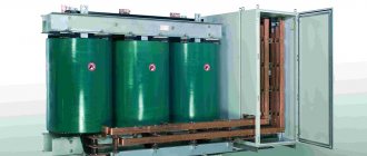
Transformer TMG-2500/6/0.4
As converters, these devices are traditionally used to bring the power sent along high-voltage lines to an acceptable form. For “transfer” over vast distances, only ultra-high voltages are suitable, at which the current can have an acceptable value.
If you try to transmit energy over at least a hundred kilometers in the form of the usual voltage of 380 Volts, a current of millions of Amperes will be required to deliver the required power to the consumer.
To dissipate it, you need a wire approximately as thick as a human body, which is impossible to implement in practice. Therefore, on the electricity-generating side, with the help of another (step-up) transformer, its value rises to 110 kV. It is impossible to use electricity distribution in residential buildings and production facilities in this form. Therefore, after delivery via HV in distribution stations, 110 kV is reduced to 10(6) kV.
From here they enter the regional transformer substations, where in the local step-down transformer they acquire their final form of 380 (220) Volts. With such potential values, energy can easily be transported via an underground cable or overhead SIP wire to the end consumer. Therefore, a single-phase transformer plays a big role in human life.
Voltage drop and resistance of transformer windings
Relative active voltage drops in the primary and secondary windings of a single-phase transformer at rated load:
In the case of a three-phase transformer, the right-hand sides of these formulas must be divided by √3. Active resistance of the windings of a single-phase transformer:
In the case of a three-phase transformer, the right-hand sides of these formulas must be divided by 3 when connecting the windings with a star.
Active short circuit resistance of a two-winding transformer, reduced to the primary winding:
where U1 and U2 are taken from the task, I1 and I2 – from position 1, W1 and W2 – from position 4, Pm and Pm2 – from position 7.
Relative inductive voltage drops in individual windings of a two-winding transformer:
eS [%] = eS1 [%] + eS2 [%] .
Inductive short circuit resistance of a two-winding transformer, reduced to the primary winding:
Where
U1 and f are taken from the task; I1 and I2 – from position 1; E1, W1 and W2 – from position 4; δ1, δ2, δ12 and H – from position 6, lω1 and lω2 – from position 7.
Short circuit impedance of a two-winding transformer:
Short circuit voltage of two-winding transformer:
In the case of a three-phase transformer, you need to divide the right side of the expression for xк, and for ek [%] - multiply by √3.
The relative change in voltage of a two-winding transformer under load can be determined by the following approximate formula:
where cos φ2 is taken from the task, cos φ1 – from position 1.
Determining the rated power of a transformer
To correctly select the rated power of a transformer (autotransformer), it is necessary to have a daily load schedule, from which both the maximum and average daily active load of a given substation, as well as the duration of the maximum load, are known.
The graph allows you to judge whether the operating conditions of the load correspond to the theoretical service life (usually 20...25 years) determined by the manufacturer.
For the relative service life of insulation and (or) for the relative wear of insulation, an expression is used that defines exponential dependences on temperature. Relative wear L shows how many times the insulation wear at a given temperature is greater or less than the wear at the nominal temperature. Wear of insulation over time is assessed by the number of hours or days spent: H=Li.
In the general case, when the insulation temperature does not remain constant over time, the wear of the insulation is determined by the integral:
In particular, the average daily wear of insulation:
The influence of insulation temperature determines how many hours the insulation can operate at a given temperature, provided that its wear is equal to the normal wear per day:
At temperatures below 80°C, insulation wear is negligible and can be neglected. The temperature of the cooling medium, as a rule, is not equal to the nominal temperature and, in addition, changes over time. In this regard, to simplify calculations, use the equivalent temperature of the cooling medium, which is understood as such a constant temperature during the calculation period at which the wear of the transformer insulation will be the same as with a changing temperature of the cooling medium in the same period.
It is allowed to take the equivalent temperature for several months or a year equal to the average monthly temperatures or determine the equivalent temperatures using special graphs of the dependence of equivalent monthly temperatures on average monthly and average annual temperatures, equivalent summer (April-August), autumn-winter (September-March) and annual temperatures on average annual temperatures.
If, when choosing the rated power of a transformer at a single-transformer substation, we proceed from the condition
(where Рmax is the maximum active load of the fifth year of operation; Рр is the design rated power of the substation), then with a schedule with a short-term load peak (0.5 ... 1.0 hours), the transformer will operate for a long time with underload. In this case, an overestimation of the rated power of the transformer and, consequently, an overestimation of the installed capacity of the substation is inevitable.
In some cases, it is more profitable to choose the rated power of a transformer close to the maximum load for a sufficient duration with full use of its overload capacity, taking into account systematic overloads in normal mode.
Checking the transformer for heating
The temperature rise of the windings and core of the transformer over the ambient temperature can be approximately determined by the formula:
where Pm – total losses in copper windings from position 7; Pс – losses in core steel from position 8; aо = (10 – 12) × 10-4 – average heat transfer coefficient of the open surface of the windings and core, W/cm2 × deg; Sser and Swind – open surfaces of the core and windings of the transformer, cm2; ΔΘ° - temperature differences from the inner layers of the windings to the outer ones, which for windings impregnated with varnish can be approximately taken as 10 - 15 ° C.
1 In order not to violate the chronology of the presentation of the material taken from the source presented below, the text indicates the GOST 802-58 standard, which is not valid today. Its current analogue is GOST 21427.1-83. Accordingly, steel grades E11, E41, E310, E320, E34, E340, E44, E47 and E48 are obsolete and are not produced. When choosing steel when calculating the core, use GOST 21427.1-83.
Source: Ermolin N.P., “How to calculate a low-power power transformer” - Leningrad: Gosenergoizdat, 1961 - 52 p.
Exploitation
When using single-phase transformers, safety precautions are given a special place. This is due to the fact that the device is under high voltage located on the primary windings. When connecting and installing a transformer in electrical circuits, it is important to follow a number of rules to avoid breakdowns and malfunctions of the device:
- To prevent the windings from failing (burning out), it is necessary to install short circuit protection on the secondary circuit;
- It is necessary to control the temperature conditions of the core and windings. It is advisable to install a cooling system that prevents a critical increase in temperature during operation.
In the case of different loads from the electrical network, its voltage also changes. For stable operation of devices receiving energy, it is necessary that the voltage does not change from a set level above the permissible range. In view of this, it is permissible to use methods of voltage regulation in the network.
Educational materials
A single-phase transformer has a closed ferromagnetic core, on which primary and secondary windings with the number of turns W1 and W2 are wound.
To reduce eddy currents, the ferromagnetic core is assembled from individual plates of electrical transformer steel with a thickness of 0.35 or 0.5 mm.
In the transformer diagram, conditionally positive directions of all quantities characterizing electromagnetic processes in the transformer are accepted, based on the premise that the primary winding of the transformer is a receiver of electrical energy, and the secondary winding is a source.
Get a decision on TOE
The operation of a transformer is based on the law of electromagnetic induction. When the primary winding is connected to an alternating current source, an alternating current I1 flows in the turns of this winding, which creates an alternating magnetic flux in the core (magnetic circuit). Closing in the core, this flux meshes with the primary and secondary windings and induces in them an emf proportional to the number of turns W:
In the primary winding, self-induction emf
in the secondary winding mutual inductance emf
When the load Zn is connected to the terminals of the secondary winding of the transformer, under the influence of the EMF, current I2 will flow in the winding, and voltage U2 will be established at the terminals.
The transformer winding connected to a network with a higher voltage is called the high voltage winding (HV). The winding connected to the lower voltage network is called the low voltage (LV) winding.
The transformation coefficient K of a transformer is the ratio of the EMF of the HV winding (number of turns Win) to the EMF of the LV winding (number of turns Wnn):
Transformers have the property of reversibility, that is, the same transformer can be used as a step-up and step-down transformer.
A transformer is an alternating current device and does not operate on direct current, since the direct current flowing through the primary winding will create a constant magnetic flux. In accordance with the law of electromagnetic induction, the flux must change both in magnitude and direction.
In the load mode of the transformer, the primary and secondary currents I1, I2, in addition to the main magnetic flux Фо, create magnetic leakage fluxes Фσ1 and Фσ2, the influence of which determines the existence of inductive reactances of the primary and secondary windings of the transformer X1 and X2.
The active and impedance of the primary winding of the transformer are designated R1 and Z1, and the secondary winding - R2 and Z2.
The operation of a transformer is generally described by a system of equations:
where I0 is the no-load current.
Equation (1) and (2) are the equilibrium equations for the EMF of the primary and secondary windings, equation (3) is the equilibrium equation for the magnetizing forces (I⋅W) of the transformer. Magnetizing (magnetomotive) force is the product of current and the number of turns of the winding.
Having performed the transformations in equation (3), we obtain:
From equation (4) it follows that the current I1 of the primary winding of the transformer can be considered consisting of two components: one component I0 determines the main magnetic flux Ф0, and the second component
compensates for the demagnetizing effect of the current I2 of the secondary winding. From the above it follows that the magnetic flux in the transformer does not depend on the load current and is proportional to the applied voltage.
If we neglect the no-load current I0 (a few percent of I1) of the transformer flowing through the primary winding (with the secondary winding open), then we can consider the currents in the windings of the transformer to be inversely proportional to the number of turns.
The following operating modes of the transformer are possible:
- idle mode;
- short circuit mode (emergency mode and short circuit experience);
- load mode.
In no-load mode, the transformer operates with the secondary winding open.
In this case, the following relationships exist:
I2 = 0; I1 = I0 (no-load current); U2 = E2
The no-load power P0 consumed by the transformer from the network is determined mainly by losses in the steel core PC.
P0≈Pc (is 1-2% of rated power)
Losses in steel consist of losses due to magnetization reversal of the ferromagnetic material of the core and losses due to eddy currents, which are induced in the core in accordance with the law of electromagnetic induction. To reduce eddy current losses, the core is made of thin plates (0.3-0.5 mm), insulated from each other.
The no-load test of the transformer is carried out to determine the transformation coefficient K and the power of electrical losses in the steel core.
A transformer short circuit experiment is carried out to determine the power of electrical losses in the transformer windings (copper losses Рм). When conducting a short circuit experiment, the secondary winding of the transformer is short-circuited, while a reduced voltage U1K, amounting to 5-10% of the rated voltage, is supplied to the primary winding. During the experiment, the currents in the windings of the transformer are monitored and the experiment is stopped when the currents in the windings reach nominal values.
The passport data of the transformer includes the no-load current as a percentage of the rated value, the power losses in the windings and the voltage in the short circuit experience, expressed as a percentage of the rated value.
The load mode of a transformer is the mode of its operation when the secondary winding is connected to the load resistance Zn.
The power P1 consumed by the transformer from the network in load mode is determined by the formula:
Р1 = Р2 + ΣР = Р2 + Р0 + Рм,
where P2 is load power;
ΣР – total losses of the transformer (in steel and copper).
Transformer efficiency
has a maximum value when losses in the wires of the windings and losses in the steel of the core are equal
Р0=Рм.
The transformer is designed so that ηmax occurs at the most probable load component (0.5 - 0.75) P2nom..
For a transformer operating under load, the secondary voltage U2 differs from the no-load voltage U20 by the amount of the voltage drop across the impedance of its secondary winding
which is called transformer voltage change
For transformers produced by industry, the ΔU value is 6-8% of U2 nom. (secondary rated voltage). It is useful to know that from the short-circuit voltage U1к obtained in the short-circuit experiment, one can judge the deviation of the voltage of the secondary winding of the transformer from its rated value at the rated current (load).
The change in voltage in the transformer depends not only on the current values of the primary and secondary windings I1 and I2, but also on the type of load (reactive, inductive or capacitive).
The external characteristic of the transformer is the dependence of the voltage U2 of the secondary winding on the current I2 flowing through it, U2=f(I2).
Rice. 13. External characteristics of the transformer
The vector diagram of the transformer is constructed based on the equilibrium equations of the EMF of the primary and secondary windings and the equilibrium equation of the magnetizing forces of the transformer (equations 1, 2, 3).
Next > Lectures on TOE >
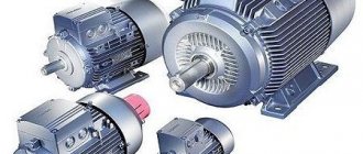
Types of transformers and their applications
Types of transformers
Based on the design features of the core, known samples of single-phase transformers are divided into rod, ring and armored products. According to the shape of the magnetic circuit used in them, they can be:
- W-shaped;
- Toroidal;
- U-shaped.
Each of these forms is suitable for specific purposes related to the need to obtain specified transfer characteristics.
Based on the value of the maximum achievable magnetic coupling (MC), transformers are divided into products with strong, medium and weak interaction. These characteristics largely depend on the design of the product itself and the type of its core.
A single-phase transformer is in demand in areas where it is necessary to coordinate two power circuits with electrical isolation of each of them.