Content
- 1. General part
- 2. Initial data for calculation
- 3. Calculation of element resistances
- 4. Calculation of three-phase short circuit currents at point K1
- 5. Calculation of three-phase short circuit currents at point K2
- 5.1 For the middle position of the on-load tap-changer regulator of transformer T3
- 5.2 For the minimum position of the on-load tap-changer regulator of transformer T3
- 5.3 For the maximum position of the on-load tap-changer regulator of transformer T3
- 6. Calculation of three-phase short circuit currents at point K3
- 6.1 Resistance on the busbars of a 6 kV closed switchgear with the on-load tap-changer of transformer T3 set to the middle position
- 6.2 Resistance on the busbars of a 6 kV closed switchgear with the on-load tap-changer of transformer T3 set to the negative position
- 6.3 Resistance on the busbars of a 6 kV closed switchgear with the on-load tap-changer of transformer T3 set to the positive position
- 7. Calculation of short circuit current performed in Excel
- 8. References
The essence of the process
When any electrical device is connected to the circuit, the line shorts. An electric current begins to pass through it. It flows from the power source through the load (consumer) and returns. The current strength is determined by the load resistance of the elements connected to the circuit. If R is large, the magnitude of the current is small. Otherwise, it can reach large values. A situation in which an electrical connection occurs between the positive and negative contacts of an electrical line is called a short circuit.
For example, you can imagine a simple circuit consisting of a current source and an incandescent lamp. In order for it to light up, one of the source terminals (phase) should be connected to one of the lamp electrodes, and the other to the second contact of the lighting device (zero). A current will appear in a closed circuit, which, passing through the tungsten conductor of the lamp, will lead to its heating and emission of light. This type of work is called regular or normal work.
But if for some reason there is an additional contact between the terminals of the power source, and its resistance is negligible, almost all of the generated current will flow through it. The supply phase will be shunted to zero. As a result, all the voltage will be applied to the terminals of the generating device. And the current strength generated in the circuit will be determined only by the internal resistance of the power source.
The current strength will increase sharply. Taking into account the Joule-Lenz law, which determines the thermal effect of electric current, the heating of the electrical circuit will increase. If the current strength during a short circuit increases by 2 times, the generated heat will increase by 40 times. The phenomenon is often accompanied by wire melting and fire. This is why it is so important to be able to calculate short circuit currents for 110 V, 220 V or 380 V. These are the voltages that are used in everyday life and industry, ensuring the operation of electrical appliances and installations.
The following types of short circuit are distinguished:
- single-phase - establishing contact between the phase line and the zero line;
- two-phase - phase closure between each other or their common connection to the ground;
- three-phase - observed in 380 volt networks when three phases are connected.
It should be noted that a short circuit will occur only if the connection has the least resistance in the closed section of the circuit than that provided for in normal operation. It is determined in accordance with GOST and the rules for electrical installations (PUE).
a common part
It is required to calculate the three-phase short circuit current (SSC) on the buses of the designed indoor switchgear-6 kV substation 110/6 kV "GPP-3". This substation is powered by two 110 kV overhead lines from the 110 kV GPP-2 substation. The ZRU-6 kV “P4SR” receives power from two power transformers TDN-16000/110-U1, which operate separately. When one of the inputs is disconnected, it is possible to supply power to the de-energized bus section via a section switch in automatic mode (ATS).
Figure 1 shows the design diagram of the network
Figure 1 – Network design diagram
Since the chain from I N.S. "GPP-2" to I northern latitude. “GLP-3” is identical to chain II s.sh. from "GPP-2" to II northern latitude. "GPP-3" calculation is carried out only for the first chain.
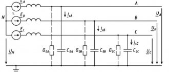
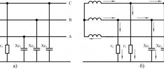
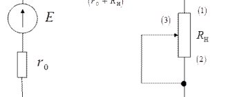
The equivalent circuit for calculating short-circuit currents is shown in Figure 2.
Figure 2 – Network equivalent circuit
The calculation will be made in named units.
Why do you need to know the values of the short-circuit current and the resistance of the “Phase-zero” loop?
I have already said a lot of things in the article. But what good is it to us to know these parameters of the power grid?
Knowing the short-circuit current (or the resistance of the “Phase-zero” loop) and the load power allows us to correctly and optimally (in terms of safety/functionality/reliability/price ) select the main elements of the power system - protection devices and cable cross-sections. A little more detail below.
Safety
I have already spoken about this, but I will repeat it. Electrical networks must be safe in all areas and in all modes. For this, in addition to insulation, circuit breakers and devices controlled by differential current (RCD) are used. Together with protective grounding, these devices protect equipment from short circuits and overloads, and people from the danger of direct or indirect contact.
Functionality
Knowing the short-circuit current, you can issue a conclusion about the need to install a stabilizer, or replace the cable line with a new one. In addition, we can draw a conclusion about selectivity - can it be ensured at least partially?
Reliability
In case of high short-circuit current, it is necessary to use switches with high breaking capacity for reliable operation at the moment of short-circuit. In addition, high demands must be placed on the quality of installation and components.
Price
It’s clear here - fulfilling the previous points significantly affects the price of the entire electrical network.
Initial data for calculation
- 1. System data: Is=22 kA;
- 2. VL data - 2xAS-240/32 (Data are given for one circuit AS-240/32, RD 153-34.0-20.527-98, Appendix 9):
- 2.1 Positive sequence inductive reactance - X1ud=0.405 (Ohm/km);
- 2.2 Capacitive conductivity - bsp = 2.81x10⁻⁶ (S/km);
- 2.3 Active resistance at +20 C per 100 km of line - R=R20C=0.12 (Ohm/km).
- 3. Transformer data (taken from GOST 12965-85):
- 3.1 TDN-16000/110-U1, Uin=115 kV, Unn=6.3 kV, on-load tap-changer ±9*1.78, Uk.inn-nn=10.5%;
- 4. Flexible conductor data: 3xAC-240/32, l=20 m. (To simplify the calculation, the resistance of the flexible conductor is not taken into account.)
- 5. Data of the current-limiting reactor - RBSDG-10-2x2500-0.2 (taken from GOST 14794-79):
- 5.1 Rated current of the reactor - Inom. = 2500 A;
- 5.2 Nominal power losses per reactor phase - ∆P= 32.1 kW;
- 5.3 Inductive reactance – X4=0.2 Ohm.
Determination of circuit breaker resistances
We determine the active resistance of the contacts according to Appendix 4, Table 19 GOST 28249-93:
- for a switch for a current of 1000 A – rav1 = 0.12 mOhm;
- for a circuit breaker with a current of 200 A - rav2 = 0.60 mOhm.
Calculation of element resistances
3.1 System resistance (for voltage 115 kV):
3.2 Overhead line resistance (for voltage 115 kV):
where: n - Number of wires in one overhead line 110 kV overhead line;
3.3 Total resistance to the transformer (for voltage 115 kV):
X1.2=X1+X2=3.018+0.02025=3.038 (Ohm)
R1.2=R2=0.006 (Ohm)
3.4 Transformer resistance:
3.4.1 Transformer resistance (on-load tap-changer is in the middle position):
3.4.2 Active resistance of the transformer (on-load tap-changer is in the extreme “minus” position):
3.4.3 Active resistance of the transformer (on-load tap-changer is in the extreme “positive” position):
3.4.4 Inductive reactance of the transformer in the middle position of the on-load tap-changer:
Minimum inductive reactance of the transformer (on-load tap-changer is in the extreme “minus” position)
Where:
- half of the full (total) voltage regulation range on the high voltage side of the transformer.
Maximum inductive reactance of the transformer (on-load tap-changer is in the extreme “positive” position)
The value included in the formula above is the voltage corresponding to the extreme positive position of the on-load tap-changer, and it is equal to Umax.VN=115*(1+0.1602)=133.423 kV, which exceeds the highest operating voltage of electrical equipment equal to 126 kV (GOST 721-77 " Power supply systems, networks, sources, converters and receivers of electrical energy. Rated voltages over 1000 V"). The voltage UmaxVN corresponds to Uк%max=10.81 (GOST 12965-85).
If Umax.VN turns out to be greater than the maximum permissible for a given network (Table 5.1), then Umax.VN should be taken according to this table. The value of Uk% corresponding to this new maximum value of Umax.VN is determined either empirically or found from the appendices of GOST 12965-85.
3.4.5 Current-limiting reactor resistance (at voltage 6.3 kV):
X4=0.2 (Ohm)
Estimated value of short-circuit current
How to find out the short-circuit current? It would seem – what’s difficult? Substitute the values into the formula and count!
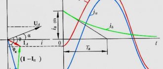
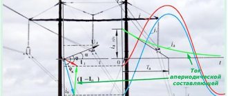
However, the full calculation of the short-circuit current is very complex, and it can be devoted to a coursework, or even a diploma project. In this case, you need to know a lot of initial data (for example, the power of the transformer at the TP and the inductive reactance of all sections of cable lines), and still the result will be theoretical, not taking into account reality - for example, contact resistances. It is also important to take into account that during a short circuit there are two current components: aperiodic (the shock part, the most powerful and unpredictable), which acts only at the initial moment during the transition process, and periodic, which practically does not change its value from the beginning to the end of the incident.
Therefore, calculations are usually left to graduate students and designers, but in practice the actual short-circuit current is measured using special instruments. For a more accurate calculation, you can use the books posted at the end of the article or calculation programs.
Calculation of three-phase short circuit currents at point K2
5.1 For the middle position of the on-load tap-changer regulator of transformer T3
5.1.1 Total resistance to point K2:
Х∑==Х1+Х2+Х3ср=3.018+0.02025+86.789=89.827 (Ohm) R∑=R2+К3=0.006+4.391=4.397 (Ohm)
5.1.2 Three-phase short circuit current:
5.1.3 The current at the short circuit, reduced to an effective voltage of 6.3 kV, is equal to:
5.1.4 Short circuit surge current:
5.2 For the minimum position of the on-load tap-changer regulator of transformer T3
5.2.1 The value of the total resistance at point K1 is reduced to a network voltage of 96.577 kV:
5.2.2 Three-phase short circuit current:
5.2.3 The current at the short circuit, reduced to an effective voltage of 6.3 kV, is equal to:
5.2.4 Short circuit surge current:
5.3 For the maximum position of the on-load tap-changer regulator of transformer T3
5.3.1 The value of the total resistance at point K1 is reduced to a network voltage of 126 kV:
5.3.2 Three-phase short circuit current:
5.3.3 The current at the short circuit, reduced to an effective voltage of 6.3 kV, is equal to:
5.3.4 Short circuit surge current:
Measurement of resistance and short circuit current of a phase zero circuit
Why measure phase-zero resistance
The zero phase circuit resistance is the total resistance of the current conductors from the measurement point to the transformer substation. To measure the loop resistance, a factory calibrated device was used. The lower the resistance, the better, the more current can flow from the substation to the consumer. The resistance of the zero phase is affected by the quality of tightening of the wires in the terminal blocks, the cross-section of the wires, the resistance on the machines, the length of the wires, and the resistance of the transformer winding at the substation. By comparing the resistance in sockets, we can determine where the wiring and connection are of good quality, and where the wiring needs to be checked.
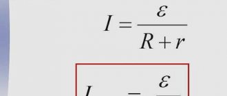
The second main purpose of measuring the resistance of a phase zero circuit is to calculate the estimated short circuit current. The short circuit current is calculated using the formula: voltage divided by the total resistance of the circuit; in modern devices it is calculated automatically. You need to know the current to understand whether the circuit breaker is selected correctly. For example, in a private house far from the substation, the line resistance is high, the short circuit current will be about 100 A. If a 25 A type C circuit breaker is installed, then the instantaneous (electromagnetic) release will only work when the current is five times higher than 125 A. And the maximum current during a short circuit If there is a short circuit, only 100 A, then during the short circuit the wiring will heat up and may catch fire until the bimetallic circuit breaker in the machine is triggered. The machine in this case should be 16 A type B and C.
The letters in the names of modular circuit breakers that are mounted on a DIN rail, the time-current characteristic of the circuit breaker means that the instantaneous electromagnetic release will work:
- B at 3…5 times the rated current;
- C at 5…10 times the rated current;
- D at 10…20 times the rated current.
In electrical networks up to 1000 V with a solidly grounded neutral, the short-circuit current must be 3 times greater than the shutdown current of the instantaneous release of the circuit breaker according to PTEEP clause 3.6. The shutdown time of the circuit breaker in 220 V networks should be no more than 0.4 s.
Having measured the estimated short circuit current in the extension cord, we found that the short circuit current through the extension cord is less than in a 100 A socket. This indicates the low power of the extension cord due to the small cross-section of the wires and poor-quality contacts.
Calculation of three-phase short circuit currents at point K3
6.1 Resistance on the busbars of a 6 kV closed switchgear with the on-load tap-changer of transformer T3 set to the middle position
6.1.1 The value of the total resistance at point K2 is reduced to a network voltage of 6.3 kV:
6.1.2 The current at the short circuit, reduced to an effective voltage of 6.3 kV, is equal to:
6.1.3 Short circuit surge current:
6.2 Resistance on the busbars of a 6 kV closed switchgear with the on-load tap-changer of transformer T3 set to the negative position
6.2.1 The value of the total resistance at point K2 is reduced to a network voltage of 6.3 kV:
6.2.2 The current at the short circuit, reduced to an effective voltage of 6.3 kV, is equal to:
6.2.3 Short circuit surge current:
6.3 Resistance on the busbars of a 6 kV closed switchgear with the on-load tap-changer of transformer T3 set to the positive position
6.3.1 The value of the total resistance at point K2 is reduced to a network voltage of 6.3 kV:
6.3.2 The current at the short circuit, reduced to an effective voltage of 6.3 kV, is equal to:
6.3.3 Short circuit surge current:
The calculation results are entered into table PP1.3
Table PP1.3 – Calculation data for three-phase short circuit currents
| Transformer on-load tap position | Short circuit currents | Short circuit point | ||
| K1 | K2 | K3 | ||
| On-load tap-changer in middle position | Short circuit current, kA | 21,855 | 13,471 | 7,739 |
| Short-circuit shock current, kA | 35,549 | 35,549 | 20,849 | |
| On-load tap-changer in minus position | Short circuit current, kA | — | 13,95 | 7,924 |
| Short-circuit shock current, kA | — | 36,6 | 21,325 | |
| On-load tap-changer in positive position | Short circuit current, kA | — | 13,12 | 7,625 |
| Short-circuit shock current, kA | — | 34,59 | 20,553 | |
How to avoid short circuit?
It is clear that it is impossible to completely avoid this unpleasant phenomenon - there is a great element of chance here. However, we are able to significantly reduce the risk of short circuits. And here regular inspection and maintenance of electrical networks becomes of enormous importance.
Examples of preventive measures:
- cleaning live parts, contacts and insulators from dust and dirt,
- checking moisture protection,
- checking the integrity of installation and installation,
- fencing and additional protection of dangerous areas,
- hanging and sticking warning signs and inscriptions,
- checking and pulling contacts,
- pruning trees and eliminating other hazardous factors.
What do you think are the necessary preventive measures to protect against short circuits in the photo below?
Drainpipe, electrical panels and corrugation that goes under the tiles. Installation in the old part of Batumi
Serious organizations regularly check cables and contacts with a thermal imager, as well as measure insulation resistance and test insulation with high voltage voltage.
Short circuit current calculation performed in Excel
If you perform this calculation using a piece of paper and a calculator, it takes a lot of time, besides, you can make a mistake and the whole calculation will go down the drain, and if the source data is constantly changing, this all leads to an increase in design time and unnecessary waste of nerves.
Therefore, I decided to perform this calculation using an Excel spreadsheet, so as not to waste my time on TKZ recalculations and to protect myself from unnecessary errors; with its help, you can quickly recalculate short-circuit currents, changing only the original data.
I hope that this program will help you and you will spend less time designing your object.
General information
All existing materials in electrical engineering are divided into 2 large classes: conductors and dielectrics. The former are capable of passing electric current through themselves. Examples of conductors include metals, and non-conductors include plastics and rubber. From a physical point of view, the ability to transmit electric current depends on the properties of materials.
As it turns out, electrons are involved in the process of charge transfer. Nature is structured in such a way that all bodies consist of atoms and molecules. They are connected to each other by electromagnetic forces. The basis of matter is the nucleus, which includes a neutron and a proton - a positively charged particle. An electron, a negative element, rotates around the center in an orbital. In a normal state, the quantity of both is the same, so the body is electrically neutral.
If an external force acts on a substance, the electrons can break their bond with the atom and become free. In this case, there may already be free particles in the structure of the material. They arise due to impurities or various defects in the crystal lattice. At rest, free particles can move chaotically through the structure.
But as soon as electromagnetic force is applied to the body, their movement becomes orderly. A phenomenon called electric current occurs. It is characterized by strength. This is a quantity that shows how many charges can flow through the cross-section of a conductor per unit time.
For current to occur, three conditions must be met:
- existence of free charge carriers;
- creation of an electromagnetic field;
- closed circuit.
The current strength can be quantitatively determined using Ohm's law: I = U/R. After conducting a series of experiments, the scientist discovered the rule according to which the value of the current is proportional to the work done to transfer charge from one point to another and inversely proportional to the resistance of the material.
The last value is a rather important characteristic. In its meaning, resistance is the inverse parameter of conductivity, that is, it determines the type of material.
Causes of short circuit
Now let's briefly look at the possible causes of short circuits.
Common causes of short circuits are as follows:
- outdated wiring;
- mechanical damage inside the circuit;
- improper organization of electrical wires;
- violation of the rules for operating an electrical appliance;
- uncontrolled increase in the power indicator of devices;
- non-compliance with construction standards.
Negative impact of short circuit for a person and his property
A short circuit, depending on the location of its occurrence, leads to detrimental consequences for property and the safety of human life. These include:
- burning and failure of electrical appliances;
- ignition of electrical wiring;
- a decrease in the voltage of the electrical network (in industrial conditions it leads to a shutdown of enterprises);
- decrease in the efficiency of power supply systems;
- the occurrence of electromagnetic influence leads to disruption of the functioning of communications located underground.