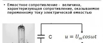
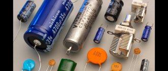
AC circuit with capacitance
Author: Evgeny Zhivoglyadov. Date of publication: March 31, 2015. Category: Articles.
If a capacitor is connected to a DC circuit (ideal - without losses), then for a short time after switching on, a charging current will flow through the circuit. After the capacitor is charged to a voltage corresponding to the source voltage, the short-term current in the circuit will stop. Therefore, for direct current, a capacitor represents an open circuit or an infinitely large resistance.
If a capacitor is connected to an alternating current circuit, it will be charged alternately in one direction and then in the other.
In this case, alternating current will pass through the circuit. Let's consider this phenomenon in more detail.
At the moment of switching on, the voltage across the capacitor is zero. If you connect the capacitor to the alternating mains voltage, then during the first quarter of the period, when the mains voltage increases (Figure 1), the capacitor will charge.
Figure 1. Graphs and phasor diagram for an AC circuit containing a capacitance
As charges accumulate on the capacitor plates, the capacitor voltage increases. When the network voltage reaches its maximum by the end of the first quarter of the period, the capacitor charges stop and the current in the circuit becomes zero.
The current in the capacitor circuit can be determined by the formula:
where q is the amount of electricity flowing through the circuit.
From electrostatics it is known:
q = C × uC = C × u,
where C is the capacitance of the capacitor; u – network voltage; uC is the voltage on the capacitor plates.
Finally, for the current we have:
From the last expression it can be seen that when (positions a, b, d) is maximum, i is also maximum. When
(positions b, d in Figure 1), then i is also equal to zero.
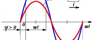
In the second quarter of the period, the network voltage will decrease and the capacitor will begin to discharge. The current in the circuit reverses its direction. In the next half of the period, the network voltage changes its direction and the capacitor is recharged and then discharged again. From Figure 1 it is clear that the current in a circuit with a capacitance in its changes is 90° ahead in phase
voltage across the capacitor plates.
Comparing the vector diagrams of circuits with inductance and capacitance, we see that inductance and capacitance have the exact opposite effect on the phase of the current.
Since we noted above that the rate of change of current is proportional to the angular frequency ω, from the formula
we similarly obtain that the rate of change of voltage is also proportional to the angular frequency ω and for the effective value of the current we have
I = 2 × π × f × C × U.
Designating
, where xC is called
capacitance , or capacitance reactance .
So we have obtained the formula for capacitance when switching on a capacitance in an alternating current circuit. From here, based on the expression of Ohm's law, we can obtain the current for an alternating current circuit containing a capacitance: Voltage across the capacitor plates
UC = IC × xC.
That part of the network voltage that is present on the capacitor is called capacitive voltage drop , or reactive voltage component , and is designated UC.
The capacitance xC, like the inductive reactance xL, depends on the frequency of the alternating current.
But if with increasing frequency the inductive reactance increases, then the capacitive reactance, on the contrary, will decrease.
Example 1. Determine the capacitive reactance of a 5 µF capacitor at different mains voltage frequencies. We will calculate the capacitance at a frequency of 50 and 40 Hz:
at a frequency of 50 Hz:
at a frequency of 400 Hz:
Let's apply the formula for average or active power for the circuit in question:
P = U × I × cos φ.
Since in a circuit with a capacitance the current leads the voltage by 90°, then
φ = 90°; cos φ = 0 .
Therefore, the active power is also zero, that is, in such a circuit, as in a circuit with inductance, there is no power consumption.
Figure 2 shows the instantaneous power curve in a circuit with a capacitance. It can be seen from the drawing that in the first quarter of the period, a circuit with a capacitor takes energy from the network, which is stored in the electric field of the capacitor.
Figure 2. Instantaneous power curve in a circuit with capacitance
The energy stored by the capacitor by the time the voltage across it passes through the maximum can be determined by the formula:
In the next quarter of the period, the capacitor is discharged to the network, giving it the energy previously stored in it.
During the second half of the period, the phenomenon of energy fluctuations repeats. Thus, in a circuit with a capacitor, only energy is exchanged between the network and the capacitor without losses.
Source: Kuznetsov M.I., “Fundamentals of Electrical Engineering” - 9th edition, revised - Moscow: Higher School, 1964 - 560 p.
To main§ 55. Capacitance in the alternating current circuit
In Chapter I, § 10, the process of charging and discharging a capacitor connected to a direct current circuit was explained. Let us now consider an alternating current circuit (Fig. 58, a), which includes an electric capacitance (capacitor). We neglect the active resistance of this circuit ( r
= 0).
The polarity of the terminals of an alternating current generator connected to a circuit with a capacitor changes with a frequency ω = 2π f
.
In the first quarter of the period (Fig. 58, c), the capacitor is charged and electric charges of opposite sign appear on its plates (plus on the left plate, minus on the right). When the capacitor is charged, electric charges move along the wires connecting the generator to the plates, therefore, a charging current flows, measured by a milliammeter. No current passes through the dielectric of the capacitor. As can be seen in the wave diagram, in the first quarter of the period while charging the capacitor, the voltage on the capacitor plates increases from zero to the maximum value, the current strength, on the contrary, at the beginning of the charge will be maximum, and at the end of the charge, when the voltage on the capacitor ( Uc
) will be equal generator voltage (
Ug
), it will become equal to zero.
During the second quarter of the period, the generator voltage gradually decreases and becomes equal to zero. At this time, the capacitor is discharged. In this case, the discharge current flowing through the wires has a direction opposite to the direction of the charge current. During the third quarter of the period, the polarity at the generator terminals will change and the voltage will increase from zero to the highest value. At this time, the capacitor will charge again, but the polarity on its plates will change. The left plate will have a negative charge and the right plate will have a positive charge. A charging current will pass through the wires, the strength of which by the end of the capacitor charge, when Uc
=
Ug
, will become zero.
In the fourth part of the period, the generator voltage decreases and becomes equal to zero. At this time, the capacitor is discharged a second time, and a discharge current flows again through the wires connecting the generator to the capacitor plates. From the above it follows that during one period of alternating voltage change the process of charging and discharging the capacitor occurs twice and at the same time alternating current flows in its circuit. In addition, when charging and discharging a capacitor, the current in the circuit and the voltage are out of phase. The current is ahead of the voltage in phase by a quarter of the period, i.e. by 90°. Let's construct a vector diagram for an alternating current circuit with a capacitance (Fig. 58, b). To do this, we plot the current vector I
on the selected scale horizontally.
To show on a vector diagram that the voltage lags behind the current by an angle φ = 90°, we plot the voltage vector Uc
down at an angle of 90°.
Let's find out what the current strength in a circuit with a capacitance depends on. Let us denote the circuit resistance Xc
and call it capacitive reactance. Then Ohm's law for a circuit with a capacitance can be expressed as follows:
where U
— generator voltage,
V
;
Xc
- capacitance,
ohm
;
I
is the current strength,
and
. It is known that the current strength in a circuit is determined by the number of electrical charges passing through the cross-section of the conductor per unit time:
If a large number of charges flow through the wires per unit of time, then the current strength will be large, and vice versa, when a small number of charges flow through the wires each second, then the current strength will be insignificant. Let us assume that the frequency of the alternating current generated by the generator is high. In this case, every second the capacitor is charged and discharged many times (frequently). In the wires running from the generator to the capacitor plates, a large amount of electrical charges will move every second. Therefore, we can say that a large current appears in the circuit under consideration and in this case, according to Ohm’s law, the capacitance of the circuit is Xc
turns out to be small. If the alternating current frequency of the generator is low, the capacitor will charge and discharge fewer times every second. In this regard, a small amount of charges will pass through the wires of the circuit every second and the current strength will be small, and therefore, the capacitance of the circuit, on the contrary, will be large. From the above we can conclude that capacitance is inversely proportional to the frequency of alternating current. Capacitance depends not only on the frequency of the alternating current, but also on the amount of capacitance included in the circuit. Let us assume that a large capacitor is connected to the circuit. The amount of electricity that a capacitor accumulates when charging and releases when discharging is directly proportional to its capacity:
q = CU
.
The larger the capacitance of the capacitor included in the alternating current circuit, the greater the amount of electricity will move during charge and discharge along the wires running from the generator to its plates. Therefore, a large current arises in the wires and in this case, according to Ohm’s law, the capacitance of the circuit is Xc
there won't be enough. If the capacitance included in the circuit is small, then during charging and discharging a smaller amount of electrical charges will pass through the wires and the current strength will be insignificant, therefore, the capacitance of the circuit, on the contrary, will be large. From the above we can conclude that capacitance is inversely proportional to capacitance. Thus, the capacitance is:
where Xc
— capacitance,
ohm
;
ω - angular frequency of alternating current, rad/sec
;
C
- capacity,
f
.
It is known that the angular frequency is ω = 2π f
. Therefore, capacitance can be defined as follows:
where f
— alternating current frequency,
Hz
. If the switched capacitance is measured in microfarads, then the capacitance
If capacitance is measured in picofarads, then
It should be emphasized that there is a significant difference between capacitive and active resistance. As you know, a resistive load irreversibly consumes the energy of the alternator. If a capacitance is connected to the alternating current source, then, as discussed above, the energy of the generator is spent when charging the capacitor to create an electric field between the plates and is returned back to the generator when the capacitor is discharged. Consequently, the capacitive load does not consume the energy of the generator, and in the circuit with the capacitance, energy is “pumped” from the generator to the capacitor and back. For this reason, capacitive reactance, like inductive reactance, is called reactive.
Example.
A capacitor with a capacity
C
= 2
μF
is connected to an alternating current circuit whose frequency is 50
Hz
.
Determine: 1) its capacitance at frequency f
= 50
Hz
;
2) the capacitance of this capacitor to alternating current, the frequency of which is 500 Hz
.
Solution. Capacitance of a capacitor to alternating current at frequency f
= 50
Hz
At frequency f
= 500
Hz
From the above example it can be seen that the capacitance of the capacitor decreases with increasing frequency, and as the frequency of alternating current decreases, the capacitance increases.
For direct current, when the voltage at the circuit terminals does not change, the capacitor practically has an infinitely large resistance and therefore does not pass direct current. Previous page
| table of contents | Next page |
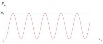
depending on the frequency and capacitance value (Fig. 1.50).
| CONCLUSIONS: 1. The current flowing through the capacitance leads the voltage by 2. Power is alternating, changing at double frequency. When the value is positive, electrical energy accumulates in the magnetic field of the capacitor. At the point in time when it is negative, it is transferred from the container to the source of electrical energy. 3. The complex resistance of the active resistance is a real value and does not depend on frequency. 4. The complex resistance of inductance is an imaginary quantity and is directly proportional to frequency. 5. The complex resistance of the capacitance is negative and inversely proportional to frequency. 6. Inductance and capacitance resistances are called reactances. 1.6. SINUSOIDAL CURRENT CIRCUITS 1.6.1. Sinusoidal current circuit with series connection of elements r, L and C. If a sinusoidal voltage is applied to a circuit consisting of elements r, L and C connected in series (Fig. 3.50),then a sinusoidal current will flow through it. Since the voltage on the active resistance is in phase with the current, on the inductance the current is ahead in phase by , and on the capacitance it is behind the phase of the current by , then based on Kirchhoff’s second law for instantaneous values, we can write: | ||||
Ideal capacity
Capacitors are ideal capacitance in an electrical circuit. In the inductor and capacitors, no active power is consumed, that is, $P=0$. At this moment, there is no transformation of energy into its other types of irreversible nature, but only the circulation of available energy is recorded. That is, electrical energy is stored in the electric field of a capacitor or the magnetic field of a coil. The process occurs approximately 25 percent of the time period. The energy is then returned to the grid.
Definition 3
The capacitor and inductor are sometimes called reactive elements due to the processes occurring in them. Their resistance is usually called reactive. The exception is a resistor, since it has active resistance.
The intensity of energy exchange is characterized by:
- the highest value of the rate of energy entering the magnetic field of the coil;
- the highest rate of energy input into the electric field of the capacitor.
This intensity is often called reactive power. The mathematical expression for reactive power is as follows:
$Q = UI sin\phi$
With an inductive load $\phi \geq 0$ the reactive power will have positive values. With a leading current in a capacitive load - negative.
The reactive power for an ideal inductor will be proportional to the maximum energy storage in the coil and the frequency.
Definition 4
Power factor is the ratio of apparent power to active power. It is equal to the cosine of the shift angle between voltage and current.
In addition to active and apparent power, the concept of complex power is used. Reactive power is characterized by circulation between the consumer and the source. Reactive current does not do work, which leads to unnecessary losses in power equipment. This leads to an increase in installed power levels. Therefore, there is currently a tendency to increase power in electrical circuits.
Many consumers in the form of various electric motors and other devices and devices use active-inductive loads. If capacitors are connected to such a load, the total consumer current will approach the phase voltage values. This means that it increases, but the total value of the current decreases, provided that the active power is constant. This fact leads to a loss of total current in electrical circuits. Capacitors are designed to increase power.
Instantaneous power
To instantly determine the power in an electrical circuit, enter a formula in the form:
Are you an expert in this subject area? We invite you to become the author of the Directory Working Conditions
$p = ui$
Instantaneous power has two types of elements:
- constant component;
- harmonic component.
Instantaneous power has an angular frequency that is twice the angular frequency of voltage and current. At negative values of instantaneous power, energy will be returned to the power source. This suggests that the directions of voltage and current have opposite values in a two-terminal network.
Such a return of energy to the source occurs due to the fact that there is an energy reserve in electric and magnetic fields at the level of capacitive and inductive elements. They are part of a two-terminal network.
Definition 2
Active power is the average value of instantaneous power over a certain period of time.
$P = UI cos \phi$
Active power when consumed by a passive two-terminal network does not have negative values. At the input of a passive two-terminal network, $cos \phi \geq 0$ will be fixed. The situation in which $P=0$ is possible in theory, but only for a two-terminal network without active resistances. It should contain:
Finished works on a similar topic
Course work Capacity and power of an electrical circuit 450 ₽ Abstract Capacity and power of an electrical circuit 220 ₽ Test work Capacity and power of an electrical circuit 210 ₽
Receive completed work or specialist advice on your educational project Find out the cost
- capacitive elements;
- ideal inductive elements.
Fig.1.48
[/td]
where is the current amplitude,
- initial phase.
The phase shift between voltage and current in a circuit with a capacitance is equal to i.e. the current in a circuit with a capacitor is 90° ahead of the applied voltage in phase (Fig. 1.49).
Complex resistance of a circuit with capacitance
INFOFIZ
Let us consider separately the cases of connecting an external alternating current source to a resistor with resistance R
, capacitor capacitance
C
and inductor
L. In all three cases, the voltages across the resistor, capacitor and coil are equal to the voltage of the AC source.
1. Resistor in AC circuit
Resistance R is called active because a circuit with such resistance absorbs energy.
Active resistance is a device in which the energy of electric current is irreversibly converted into other types of energy (internal, mechanical)
Let the voltage in the circuit change according to the law: u = Umcos ωt,
then the current strength changes according to the law: i = u/R = IRcosωt
u – instantaneous voltage value;
i – instantaneous current value;
IR
is the amplitude of the current flowing through the resistor.
The relationship between the amplitudes of current and voltage across a resistor is expressed by the relation RIR
=
UR
Current fluctuations are in phase with voltage fluctuations. (i.e. the phase shift between the current and voltage across the resistor is zero).
2. Capacitor in AC circuit
When a capacitor is connected to a DC voltage circuit, the current is zero, and when a capacitor is connected to an AC voltage circuit, the current is not zero. Therefore, a capacitor in an AC voltage circuit creates less resistance than in a DC circuit.
Relation between current amplitudes IC
and voltage
U.C.
:
The current is ahead of the voltage in phase by an angle of π/2.
3. Coil in AC circuit
In a coil connected to an alternating voltage circuit, the current strength is less than the current strength in a constant voltage circuit for the same coil. Consequently, the coil in an alternating voltage circuit creates more resistance than in a direct voltage circuit.
Relation between current amplitudes IL
and voltage
UL
:
ω LIL
=
UL
The current is out of phase with the voltage by an angle of π/2.
Now we can construct a vector diagram for a series RLC circuit in which forced oscillations occur at frequency ω. Since the current flowing through series-connected sections of the circuit is the same, it is convenient to construct a vector diagram relative to the vector representing current oscillations in the circuit. We denote the current amplitude by I
0. The current phase is assumed to be zero. This is quite acceptable, since it is not the absolute phase values that are of physical interest, but the relative phase shifts.
The vector diagram in the figure is constructed for the case when or In this case, the voltage of the external source is ahead in phase of the current flowing in the circuit by a certain angle φ.
Vector diagram for a serial RLC circuit
From the figure it is clear that
whence follows
From the expression for I
0 it is clear that the current amplitude takes a maximum value under the condition
or
The phenomenon of an increase in the amplitude of current oscillations when the frequency ω of an external source coincides with the natural frequency ω0 of an electrical circuit is called electrical resonance
. At resonance
The phase shift φ between the applied voltage and current in the circuit becomes zero at resonance. Resonance in a series RLC circuit is called voltage resonance
.
In a similar way, using a vector diagram, you can study the phenomenon of resonance when connecting elements R
,
L
and
C
(the so-called
current resonance
).
At sequential resonance (ω = ω0), the amplitudes UC
and
UL
voltages on the capacitor and coil increase sharply:
The figure illustrates the phenomenon of resonance in a series electrical circuit. The figure graphically shows the dependence of the amplitude ratio UC
voltage on the capacitor to the amplitude 0 of the source voltage from its frequency ω.
The curves in the figure are called resonance curves
.