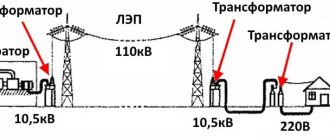
There are a number of situations in electrical installations where certain work is performed directly under voltage. This also includes all manipulations in which portable grounding is installed on disconnected current-carrying links of the circuit. Since even in a disconnected electrical installation there may be induced voltage, residual potential, which pose a threat to human life and health. Therefore, among the means to ensure personnel safety in such situations, the insulating rod stands out.
What is an insulating rod?
An insulating rod is a category of tool that allows you to isolate a worker from live elements. Structurally, it is a long pole made up of several parts, the dimensions and individual elements of which may differ depending on the characteristics of the specific device or line for which such a rod is used.
Fig. 1: Working with an insulating rod
Purpose
Depending on the situations that arise, the insulating rod can be used to solve various problems. And some models can even be equipped with a set of interchangeable heads. In practice, insulating rods may be designed to:
- Installation of portable grounding systems - in de-energized current-carrying areas to prevent electric shock to personnel in the event of incomplete disconnection of the circuit breaker or at least one of the disconnector blades from the induced and static potential.
- Fuse installations – used for electrical installations with voltages over 1 kV. In this case, a special tip with a soft gasket is installed, which prevents mechanical damage to the fuse bulb.
- Switching disconnectors - in the case when the design of the electrical installation itself allows manipulation of the insulating rod, closing or turning on the knives can be performed.
- Insulation tests - used to measure the insulation on individual insulators in strings. Test leads from measuring instruments are connected to the probes. To check, the test voltage is applied to each plate in turn by moving the insulating rod. Also used for other measurements.
- Testing the absence of voltage - can be used instead of a voltage indicator in those lines where approaching a current-carrying element is difficult due to a large distance. In this case, a special head is installed on the insulating rod, which issues a signal if there is voltage in the line.
Rice. 2: no voltage test - Searching for places where fastenings are loose – you can use an insulating rod to check the tire fixing units in case of rattling, heating or other alarming signals. In this case, the tire is pressed using a metal element, after which its condition is compared.
- Release from the action of current - if a wire falls on an electrical installation or a person, you can remove it from the victim using an insulating rod and move it to the side at a safe distance.
Rice. 3: current release by insulating rod
Device
Rice.
4: Construction of an insulating rod Structurally, such an insulating device can be divided into three main sections:
- Working - is a metal tip with a different configuration, depending on the purpose of the insulating rod.
- Insulating - designed to protect the worker from the energized section of the electrical installation where manipulations are performed. Made from dielectric material. The length of the insulating section must correspond to the voltage for which it is used.
- Handle - like the previous section, it is made of insulating materials; together they can form a monolithic rod. The handle and the insulating part are always separated by a restrictive ring, which is designed to prevent the hands from slipping to a dangerous distance.
Depending on the specific model, monolithic, folding or telescopic structures may be distinguished. This or that design can be used depending on the required length or local conditions. In accordance with their purpose, several types are distinguished.
2.2. INSTRUCTIONS FOR USE AND TESTING OF PROTECTION MEANS USED IN ELECTRICAL INSTALLATIONS
2.2. Insulating rods
Purpose and design
2.2.1. Insulating rods are designed for operational work (operations with disconnectors, changing fuses, installing parts of arresters, etc.), measurements (checking insulation on power lines and substations), for applying portable grounding, as well as for releasing the victim from electric current.
2.2.2. General technical requirements for operational insulating rods and portable grounding rods are given in the state standard.
2.2.3. The rods should consist of three main parts: working, insulating and handle.
2.2.4. Rods can be composed of several links. To connect the links to each other, parts made of metal or insulating material can be used. It is permissible to use a telescopic structure, but reliable fixation of the links at their joints must be ensured.
2.2.5. The rod handle can be one piece with the insulating part or be a separate link.
2.2.6. The insulating part of the rods must be made of the materials specified in clause 2.1.2.
2.2.7. Operating rods can have replaceable heads (working parts) to perform various operations. At the same time, their reliable fastening must be ensured.
2.2.8. The design of portable grounding rods must ensure their reliable detachable or permanent connection with grounding clamps, installation of these clamps on live parts of electrical installations and their subsequent fastening, as well as removal from live parts.
Composite portable grounding rods for electrical installations with voltages of 110 kV and higher, as well as for applying portable grounding to overhead line wires without lifting them to supports, may contain metal current-carrying links if there is an insulating part with a handle.
2.2.9. For intermediate supports of overhead power lines with a voltage of 500 - 1150 kV, the grounding structure may contain, instead of a rod, an insulating flexible element, which should be made, as a rule, of synthetic materials (polypropylene, nylon, etc.).
2.2.10. The design and weight of operational, measuring and relief rods for releasing a victim from electric current at voltages up to 330 kV must ensure that one person can work with them, and the same rods for voltages of 500 kV and higher can be designed for two people using a support device. In this case, the maximum force on one hand (supporting it at the restrictive ring) should not exceed 160 N.
The design of portable grounding rods for applying to overhead lines with a person lifting to a support or from telescopic towers and in switchgear with voltages up to 330 kV should ensure that one person can work with them, and portable grounding rods for electrical installations with voltages of 500 kV and higher, as well as for applying grounding to overhead line wires without lifting a person to a support (from the ground) can be designed for work by two people using a supporting device. The greatest force on one hand in these cases is regulated by technical conditions.
2.2.11. The main dimensions of the rods must be no less than those indicated in the table. 2.1 and 2.2.
Table 2.1
MINIMUM DIMENSIONS OF INSULATING RODS
┌─────────────────────────┬────────────── ───────── ───────────────┐ │ Rated voltage │ Length, mm │ │ electrical installations, kV ├───────────── ──────┬─ ─────────────────┤ │ │ insulating part │ handle │ ├────────────── ────────── ─┼───────────────────┴──────────────────┤ │Up to 1 │Not standardized, determined by convenience │ │ │use │ ├─────────────────────────┼─────── ─────────── ─┬──────────────────┤ │Above 1 to 15 │ 700 │ 300 │ ├──────── ────────── ───────┼───────────────────┼───────────── ─────┤ │Above 15 up to 35 │ 1100 │ 400 │ ├─────────────────────────┼───── ─────────── ───┼──────────────────┤ │Above 35 to 110 │ 1400 │ 600 │ ├───── ─────────── ─────────┼───────────────────┼─────────── ───────┤ │ 150 │ 2000 │ 800 │ ├─────────────────────────┼───── ──────────── ──┼──────────────────┤ │220 │ 2500 │ 800 │ ├──────── ──────────── ─────┼───────────────────┼─────────────── ───┤ │330 │ 3000 │ 800 │ ├─────────────────────────┼─────────── ────────┼─ ─────────────────┤ │Above 330 to 500 │ 4000 │ 1000 │ └───────── ──────────── ────┴───────────────────┴──────────────── ──┘
Table 2.2
MINIMUM DIMENSIONS OF PORTABLE GROUNDING RODS
┌───────────────────────────────────────┬ ───────── ───────────────┐ │ Purpose of rods │ Length, mm │ │ ├───────────┬─── ───────── ┤ │ │isolating│ handle │ │ │ parts │ │ ├────────────────────────── ─────────── ──┼───────────┴────────────┤ │For installation of grounding in │Not standardized, │ │electrical installations with voltage up to 1 kV │determined by convenience │ │ │ use │ ├────────────────────────────────────── ─┼─────── ────┬────────────┤ │To install grounding in the switchgear above │According to table 2.1│According to table. 2.1│ │ 1 kV up to 500 kV, for overhead line wires above │ │ │ │1 kV up to 220 kV, made entirely │ │ │ │of electrical insulating materials │ │ │ ├───────── ───── ─────────────────────────┼───────────┼─── ───────── ┤ │Composite, with metal links, │500 │According to table. 2.1│ │for installing grounding on overhead line wires │ │ │ │from 110 to 220 kV │ │ │ ├─────────────────── ───────── ───────────┼───────────┼────────────┤ │Composite, with metal links, │1000 │According to the table. 2.1│ │for installing grounding on overhead line wires │ │ │ │from 330 to 1150 kV │ │ │ ├─────────────────── ───────── ───────────┼───────────┼────────────┤ │To install grounding │700 │300 │ │isolated from lightning protection supports │ │ │ │overhead line cables from 110 to 500 kV │ │ │ ├─────────────────────── ────────── ──────┼───────────┼────────────┤ │To install grounding at │1400 │500 │ │lightning protection isolated from supports │ │ │ │overhead line cables from 750 to 1150 kV │ │ │ ├───────────────────────────── ───────── ─┼───────────┼────────────┤ │For installation of grounding in laboratory│700 │300 │ │and test installations │ │ │ ├──── ───────────────────────────────────┼───── ──────┴── ──────────┤ │To transfer the potential of the wire │Not standardized, │ │ │determined by convenience │ │ │use │ └────────── ───────── ────────────────────┴──────────────────── ────┘
Note to table 2.2. The length of the insulating flexible grounding element of a rodless design for overhead line wires from 35 to 1150 kV must be no less than the length of the grounding wire.
Performance tests
2.2.12. During operation, mechanical tests of rods are not carried out.
2.2.13. Electrical tests with increased voltage of the insulating parts of operational and measuring rods, as well as rods used in testing laboratories for supplying high voltage, are carried out in accordance with the requirements of section 1.5. In this case, voltage is applied between the working part and a temporary electrode placed at the restrictive ring on the side of the insulating part.
The heads of measuring rods for monitoring insulators in electrical installations with voltages of 35 - 500 kV are also tested.
2.2.14. Portable grounding rods with metal links for overhead lines are tested according to the method of clause 2.2.13.
Testing of other portable grounding rods is not carried out.
2.2.15. An insulating flexible grounding element of a rodless design is tested in parts. For each 1 m section, a portion of the total test voltage is applied, proportional to the length and increased by 20%. It is allowed to simultaneously test all sections of an insulating flexible element wound into a coil so that the length of the semicircle is 1 m.
2.2.16. The standards and frequency of electrical testing of rods and insulating flexible grounding elements of a rodless design are given in Appendix 7.
Terms of use
2.2.17. Before starting to work with rods that have a removable working part, you need to make sure that the threaded connection of the working and insulating parts does not “jam” by screwing and unscrewing them once.
2.2.18. Measuring rods are not grounded during operation, except in cases where the principle of the rod design requires its grounding.
2.2.19. When working with an insulating rod, you should climb onto a structure or telescopic tower, as well as descend from it, without a rod.
2.2.20. In electrical installations with voltages above 1000 V, insulating rods should be used with dielectric gloves.
Kinds
All insulating rods can be divided into the following types:
- Operational – used to perform various operations with live elements. In practice, operational rods are used to switch disconnectors, clean the insulation and remove any blockages, check the absence of voltage, change arresters, etc.
- Measuring – designed to perform measurements and control of insulators in energized circuits. Measuring rods, unlike others, are equipped with a special attachment or measuring head.
- Repair - used for installation or repairs that are carried out in close proximity to live parts.
- Universal – allows you to solve a fairly wide range of tasks and is equipped with a set of interchangeable tools. Which is applied depending on the operation being performed. In industry they are called SHIU rods.
Regardless of the type, in order to ensure the protective parameters declared by the manufacturer, these devices must be subjected to both an external inspection before direct use and periodic tests for electrical strength.
Test method
When conducting electrical tests, increased voltage is applied to the insulating links. For models with voltages ranging from 1 to 35 kV, three times the line voltage is applied, but not less than 40 kV. For insulating rods of 110 kV or more, their electrical insulation is checked with three times the phase voltage. Voltage should be applied to the insulating section from the ring to the working tip for 5 minutes by setting the alternating current to 50 Hz.
Tests of the operating rod must be carried out at least once every 24 months, and the measuring rod at least once every 12 months.
Application areaIn operation, protective equipment is subjected to operational periodic and extraordinary tests. Extraordinary tests of protective equipment are carried out according to the standards of operational tests and are carried out after repair, replacement of any parts and assemblies, in the presence of visible malfunctions and damage to protective equipment.
All electrical tests of high-voltage protective equipment must be carried out by specially trained people, which is associated with increased responsibility and danger of the work performed.
Testing of rubber protective equipment can be carried out with direct (rectified) current. When testing with direct current, the test voltage should be 2.5 times the test voltage of alternating current with a frequency of 50Hz. The current flowing through the product is not standardized. The duration of the test is the same as for the AC test.
Basic protective equipment intended for use in electrical installations with voltages above 1000 V and up to 110 kV are tested with a voltage equal to three times the linear voltage, but not lower than 40 kV, and those intended for electrical installations with voltages from 110 kV and above - equal to three times the phase voltage.
Additional protective equipment is tested at a voltage independent of the voltage of the electrical installation in which they are used. The duration of application of the test voltage is 1 minute for porcelain insulation, and 5 minutes for insulation made of solid organic materials (for example Bakelite). For rubber insulation, during operational tests, the duration of application of the test voltage is 1 minute.
Breakdown, overlap and discharges on the surface of the test medium are established according to the readings of measuring instruments and visually. Currents flowing through the product are standardized for voltage indicators up to 1000V, rubber products and insulating devices designed to operate under voltage. Protective equipment made from solid organic materials should be checked immediately after testing by touch to determine the presence or absence of local heating due to dielectric losses.
If a breakdown occurs, surface overlap, surface discharges, an increase in current through the product above the rated value, or the presence of local heating from dielectric losses, the protective equipment must be rejected and removed from service.
This technique applies to electrical testing of protective equipment.
Test object.
Electrical protective equipment includes:
• Insulating rods of all types (operational, measuring, for applying grounding);
• Insulating and electrical clamps;
• Voltage indicators of all types and voltage classes (with a gas-discharge lamp, non-contact, pulse type, with an incandescent lamp, etc.);
• Non-contact voltage detectors;
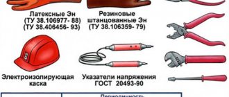
• Insulating tool;
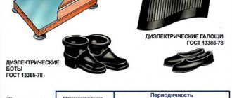
• Dielectric gloves, boots, galoshes, carpets, insulating stands;
• Protective fences (boards, screens, insulating linings, caps);
• Portable grounding;
• Devices and devices to ensure occupational safety when carrying out tests and measurements in electrical installations (voltage indicators for checking phase coincidence, devices for puncturing cables, a device for determining the voltage difference in transit, cable damage indicators, etc.);
• Posters and safety signs;
• Other protective equipment, insulating devices and devices for repair work under voltage in electrical installations with voltages of 110 kV and above, as well as in electrical networks up to 1000 V (polymer and flexible insulators; insulating ladders, ropes, inserts of telescopic towers and lifts; rods for transfer and potential equalization ; flexible insulating coatings and linings, etc.).
Insulating electrical protective equipment is divided into basic and additional.
The main electrical protective equipment in electrical installations above 1000V include:
• Insulating rods of all types;
• Insulating and electrical clamps;
• Voltage indicators;
• Devices and devices to ensure occupational safety when carrying out tests and measurements in electrical installations (voltage indicators for checking phase coincidence, devices for cable puncture, cable damage indicators, etc.);
• Other protective equipment, insulating devices and devices for repair work under voltage in electrical installations with voltages of 110 kV and higher (polymer insulators, insulating ladders, etc.).
Additional electrical protective equipment in electrical installations with voltages above 1000V include:
• Dielectric gloves;
• Dielectric boots;
• Dielectric carpets;
• Insulating supports and covers;
• Insulating caps;
• Bars for transferring and leveling potential.
The main electrical protective equipment in electrical installations with voltages up to 1000V include:
• Insulating rods;
• Insulating and electrical clamps;
• Voltage indicators;
• Dielectric gloves;
• Isolating tool.
Additional electrical protective equipment for working in electrical installations up to 1000V include:
• Dielectric galoshes;
• Dielectric carpets;
• Insulating supports and covers;
• Insulating caps.
In addition to the protective equipment listed above, personal protective equipment (PPE) of the following classes is used in electrical installations:
• Head protection (protective helmets);
• Eye and face protection (goggles and protective shields);
• Respiratory protection equipment (gas masks and respirators);
• Hand protection (mittens);
• Means of protection against falls from height (safety belts and safety ropes).
When using basic electrical protective equipment, it is sufficient to use one additional one, except for the cases specified in the “Rules for the use and testing of protective equipment used in electrical installations, technical requirements for them.”
Determined characteristics.
Operating insulating rods and portable grounding rods.
Visual inspection. The dimensions of the rods must comply with the technical specifications. If the varnish coating is damaged (cracks, deep scratches) or other malfunctions of electrical protective equipment, it is necessary to remove them from service.
Electrical tests. During operational tests, the insulating part of the operational and measuring rods is tested with increased voltage, and the voltage is applied to the working part and a temporary electrode placed at the restrictive ring on the side of the insulating part.
Insulating operating rods for voltages up to 1000V during operational tests must withstand an increased voltage of 2 kV for 5 minutes.
Insulating operating rods for voltages over 1000V up to 35 kV inclusive must withstand for 5 minutes an increased alternating current voltage with a frequency of 50 Hz, equal to three times linear, but not less than 40 kV, for voltages of 110 kV and above - equal to three times phase.
Portable grounding rods with metal links for overhead lines must withstand increased AC voltage with a frequency of 50 Hz for 5 minutes:
• For 110-220kV - 50kV
• For 330, 400, 600 kV - 100 kV
• For 750kV - 150kV • For 1150kV - 200kV
Operational electrical tests of the remaining portable grounding rods are not carried out.
During operational tests, the heads of measuring rods for monitoring insulators for voltages of 35-500 kV are tested with a voltage of 80 kV for 5 minutes.
Isolating pliers.
Visual inspection. The dimensions of the pliers must comply with the technical specifications. An external examination of the pliers determines the condition of the varnish covers, the presence of rubber tubes on the metal jaws, and the presence of a restrictive ring separating the insulating part of the pliers from the handle. If defects are detected, the pliers are rejected.
Electrical tests. Testing of electric clamps for voltages up to 1000V for electrical strength during operational tests should be carried out by applying a test voltage of 2 kV for 5 minutes between metal clamps placed on the handles (behind the thrust protrusions) on the side of the insulating part and on the jaws at the base of the oval cutout.
Testing the electrical strength of clamps for voltages of 6-10 and 35 kV during operational tests is carried out by applying a test voltage equal to three times linear, but not less than 40 kV and 105 kV, respectively, for 5 minutes to the working part and a temporary electrode applied at the restrictive ring on the insulating side parts.
Voltage indicators above 1000V with gas discharge lamp.
Visual inspection. The dimensions of the voltage indicators must comply with the technical specifications. An external inspection checks the condition of the varnish or the general condition of the insulation, connections and the integrity of the indicator lamp. If defects are detected, the pointer is rejected.
Electrical tests. Operational testing of voltage indicators consists of applying increased voltage separately to the working and insulating parts and determining the indication voltage of the indicator. When testing the working part, voltage is applied to the tip contact and the screw connector. If the pointer does not have a screw connector connected to the electrical circuit of the working part, then a temporary electrode is installed on its surface near the boundary of the latter to connect the test installation wire.
The test voltage for longitudinal insulation should have the following value:
• 12kV – up to 10kV
• 17kV – 15kV
• 24kV - 20kV Test duration - 1 minute.
In voltage indicators 35-220 kV, the working part is not tested. The voltage indicator indication voltage should be no more than 25% of the rated voltage of the electrical installation for all voltage classes.
For voltage classes up to 3 kV inclusive, the indication voltage must be determined in the technical specifications. The insulating part of the voltage indicators must withstand for 1 minute three times the line voltage for electrical installations with voltages over 1 to 110 kV and three times the phase voltage for electrical installations from 110 kV and above, but not less than the following values:
• 40kV – up to 10kV
• 60kV – over 10 to 20kV
• 105kV – over 20 to 35kV
• 190kV – 110kV
• 380kV – over 110 to 220kV
Voltage indicators up to 1000V.
Visual inspection. The dimensions of the voltage indicators must comply with the technical specifications. An external inspection checks the condition of the varnish or the general condition of the insulation, connections and the integrity of the indicator lamp. If defects are detected, the pointer is rejected
Electrical tests. Operational tests of voltage indicators up to 1000V consist of determining the indication voltage, checking the circuit with increased voltage, measuring the current flowing through the indicator at operating voltage, and testing insulation with increased voltage. The indication voltage of voltage indicators up to 1000V should be no higher than 90V. The test voltage for checking the circuit must exceed the highest operating voltage by at least 10%. Test duration is 1 minute.
The value of the current flowing through the indicator at the highest operating voltage should not exceed:
• 0.6 mA for single-pole voltage indicator;
• 10 mA for a two-pole voltage indicator with elements providing visual or visual-acoustic signaling;
• for voltage indicators with an incandescent lamp up to 10 W with a voltage of 220V, the current value is determined by the power of the lamp.
The insulation of voltage indicators up to 500V must withstand a voltage of 1 kV, and for voltage indicators above 500V - 2 kV. Test duration is 1 minute.
Voltage indicators for checking phase coincidence.
Visual inspection. The dimensions of the voltage indicators must comply with the technical specifications. An external inspection checks the condition of the varnish or the general condition of the insulation, connections and the integrity of the indicator lamp. If defects are detected, the pointer is rejected
Electrical tests. During operational tests, the indicators are checked according to consonant and counter-connection schemes, the electrical strength of the working and insulating parts and the connecting wire is checked. During the test, the indicator indication voltage is recorded, the value of which, depending on the circuit, is given in Table 1.
When checking the electrical strength of the longitudinal insulation of working parts, the test voltage is applied for 5 minutes to the metal connector and the wire bandage placed at the restrictive ring.
In this case, the test voltage should have the following value:
• 12kV – up to 10kV
• 17kV – 15kV
• 24kV – 20kV
• 70kV – 35kV
• 100kV – 110kV
When checking the electrical strength of the longitudinal insulation of insulating parts, the test voltage is applied for 5 minutes to the metal connector and the wire bandage applied at the restrictive ring.
In this case, the test voltage must have the following values:
• 40kV – up to 10kV
• 60kV – over 10 to 20kV
• 105kV – over 20 to 35kV
• 190kV – 110kV
The flexible wire is tested at a voltage of 20 kV for 1 minute for indicators up to 20 kV. for 35-110 kV indicators, the test voltage value for a flexible wire is 50 kV.
Electrical clamps.
Visual inspection. All individual parts of the pliers must be securely fastened together. The dimensions of the pliers must comply with the technical specifications. An external examination of the pliers determines the condition of the varnish covers, the presence of rubber tubes on the metal jaws, and the presence of a restrictive ring separating the insulating part of the pliers from the handle. If defects are detected, the pliers are rejected.
Electrical tests. Clamps for electrical installations above 1000V are tested during operational tests with a voltage equal to three times the linear voltage, but not less than 40 kV, for 5 minutes.
Clamps for electrical installations up to 1000V are tested for 5 minutes at a voltage of 2kV.
Cable piercing devices.
Visual inspection. The design of the device must ensure reliable fastening to the cable being pierced and automatically orient the axis of the cutting element with the diameter of the cable being pierced.
Electrical tests. During operational tests, the insulating parts of the devices (insulating rod or insulating insert of the electric drive) are tested with an increased voltage of 40 kV for 5 minutes.
The test voltage is applied to the insulating part of the rod or the metal flange of the electric drive and a special terminal.
Rubber dielectric gloves.
Visual inspection. In electrical installations, seamless gloves made of natural rubber latex or gloves with a seam made of sheet rubber, made by stamping, can be used. It is allowed to use only gloves marked with the protective properties En and Ev.
The length of gloves must be at least 350 millimeters. If punctures in gloves, breaks, etc. are detected. damaged gloves are discarded.
Electrical tests. Gloves are tested once every 6 months with an increased voltage of 6 kV for 1 minute, the current through the gloves should not exceed 6 mA.
Boots, dielectric rubber galoshes.
Visual inspection. Dielectric shoes should be different in color from other shoes. Galoshes and boots consist of a rubber top, rubber corrugated sole, textile lining and internal reinforcing parts. Boots must have lapels. Uniform boots can be produced without lining. The height of the bot must be at least 160 millimeters. Rubber parts must be free of cracks and breaks; if defects are detected, the products are rejected.
Electrical tests. In operation, dielectric galoshes are tested with a voltage of 3.5 kV, and boots - with a voltage of 15 kV for 1 minute.
The currents flowing through the products should be no more than 2 mA for galoshes and 7.5 mA for boots.
Rubber dielectric carpets and insulating supports.
Visual inspection. If defects are detected in the form of punctures, tears, cracks, etc. carpets should be replaced with new ones. Inspections should be carried out at least once every 6 months.
The supports are inspected once every 3 years for any violations of the integrity of the supporting insulators, kinks, or weakening of the connection between individual parts of the flooring. If these defects are detected, the stands will be rejected.
Electrical tests. Carpets and stands are not subject to electrical testing.
Test and measurement conditions
Tests, as a rule, should be carried out with alternating current at a frequency of 50 Hz, at a temperature of 10 to 25 degrees C.
The rate of voltage increase to 1/3 of the test value can be arbitrary; further increase in voltage should be smooth and fast, but allowing for voltages greater than . tester to count the readings of the measuring device.
When the required voltage value is reached, after waiting a standardized time it must be quickly reduced to zero, or if the value is equal to 1/3 or less of the test value, it must be turned off (GOST 1516.2-76)
Atmospheric pressure and humidity do not affect the quality of the tests, but are recorded for recording data in the protocol. This is due to the fact that basically all tests are carried out in direct contact of protective equipment with water
Measuring instruments.
High-voltage tests of protective equipment are carried out in installations specially designed for this purpose, in which the operator is separated from the high voltage by a mesh or solid fence.
AII-70 units or others of similar design can be used as sources of increased voltage. All devices must be verified and testing facilities certified by the relevant government agencies (NatsEKS).
Procedure for testing and measurements.
During testing, increased voltage is applied to the insulating parts of the protective equipment. In the absence of a voltage source with the required output voltage, it is allowed to test the protective equipment in parts. In this case, the insulating part of the protective equipment is divided into sections to which part of the test voltage specified by the standards is applied, and the voltage must have a value proportional to the length of the section with an increase of 20%.
High-voltage tests of operating rods and voltage indicators:
Schemes for testing are presented in Figures 1, 2, 3 and 4.
T-1 - control transformer, T-2 - V/volt transformer, 3 - kilovoltmeter, 4 - test wire, 5 - water bath, 6 - electrode.
After high-voltage testing of protective equipment, they should be checked for the absence of local heating due to dielectric losses.
Testing protective equipment made of dielectric rubber.
When testing dielectric gloves, they are immersed in a metal vessel with water, which is also poured inside the products.
The water level both inside and outside the products should be 50 millimeters below the top edge of the gloves. Exposed edges must be dry.
The test diagram is shown in Figure 5.
T-1 - regulating transformer, T-2 - V/volt transformer, 3 - switching contacts, 4 - shunt resistor (15-20 kOhm), 5 - gas-discharge lamp, 6 - inductor, 7 - milliammeter, 8 - arrester, 9 - bath with water.
When testing dielectric shoes, the water level both outside and inside horizontally installed products should be 20 millimeters below the sides of the galoshes and 50 millimeters below the edge of the lowered lapels of the boots. The tests are carried out similarly to the gloves test (see diagram in Figure 5).
Processing of data obtained during testing.
The primary entries in the workbook must contain the following data: date of measurements. temperature, humidity and pressure product name external inspection results test results measurement circuit used
All test data are compared with the requirements of the normative and technical documentation and, based on the comparison, a conclusion is issued on the suitability of the object for operation.
Requirements for insulating rods
According to established standards, these devices must meet the following requirements:
- Each model must include at least three parts. If lengthening or folding is necessary, a larger number of elements can be used in composite rods, but without compromising the insulating gap.
- The design of the working tip must be securely attached to the insulating element, preventing instability or movement.
- The tip must clearly grasp the element for which it is intended - fuses, disconnector blades, wire clamps and others. Do not use a particular boom or attachment for purposes other than its intended purpose.
- In relation to protective grounding, the rod design must reliably fix the grounding cable for tightening and unscrewing the clamp.
- The design of the grounding and its fixing points must prevent the clamp from falling out, which can occur from a dynamic shock when they conduct short-circuit current.
- The force applied to the handle should not be more than 80 N for measuring and no more than 160 N for all others. The rod must be operated by one worker; only for models rated at 500 kV or more, its layout and installation must be controlled simultaneously by two people.
Terms of use
Rice.
5: how to use an insulating rod To ensure safety during any manipulations, a number of rules must be followed. Thus, in electrical installations of more than 1 kV it is necessary to wear dielectric gloves and a face shield. Since in the event of voltage on the elements of an electrical installation, gloves act as an additional protective device designed to prevent potential contact with a person in any emergency situations. The gloves themselves, as well as the insulating rod, must be checked before starting work for integrity and compliance with the test dates.
If during the work the varnish coating on the insulating elements was damaged, then such a rod must be removed for repair. And after the varnish area is restored, it must undergo an extraordinary test. If, before starting work, cracks, chips or more serious damage are discovered, then such a device must be permanently removed.
It is strictly forbidden to perform any manipulations with operational, measuring or control rods from ladders, stands and other structures that reduce the stability of the worker. Since if a person stumbles or staggers, there is a high probability that he will fall and may become under tension.
It should be noted that all insulating rods must be periodically cleaned of any contaminants that may accumulate on their surface. Since dust, moisture and other substances become conductors of electric current. And for hollow tubular structures, it is also necessary to clean the inner surface in order to prevent the possibility of breakdown along the inner surface.
It is strictly prohibited to perform work with such devices during heavy rain, snow, or fog. Since sediments form a conductive layer on the surface, which can negate the dielectric properties.
Telescopic and folding booms should only be transported to the work site in a folded state. And directly on the spot it is brought into a decomposed state. When moving insulating rods within the outdoor switchgear and rooms with electrical installations, they must be in a horizontal position parallel to the ground. To prevent accidental contact with live elements, especially those that do not correspond to the model class, and to prevent overlapping of the insulating layer.
For safety reasons, it is prohibited to wrap a portable grounding rod around an insulating rod. Both protective agents must be carried separately.
ELECTROlaboratory
Good day, dear friends!
Today I will dwell in more detail on insulating rods, because... questions still arise.
So, insulating rods are electrical protective equipment.
Insulating rods are among the main protective equipment both in installations up to 1000V and in installations above 1000V.
PURPOSE AND DESIGN.
Insulating rods are designed for operational work (operations with disconnectors, changing fuses, installing parts of arresters, etc.), measurements (checking insulation on power lines and substations), for applying portable grounding, as well as for releasing the victim from electric current.
General technical requirements for operational insulating rods and portable grounding rods are given in the state standard GOST 20494. Operating insulating rods and portable grounding rods. General technical conditions.
The rods should consist of three main parts: working, insulating and handle.
Rods can be composed of several links. To connect the links to each other, parts made of metal or insulating material can be used. It is permissible to use a telescopic structure, but reliable fixation of the links at their joints must be ensured.
The rod handle can be one piece with the insulating part or be a separate link.
The insulating part of the rods must be made of electrical insulating materials that do not absorb moisture, with stable dielectric and mechanical properties.
The surfaces of the insulating parts must be smooth, without cracks, delaminations or scratches.
The use of paper-bakelite tubes for the manufacture of insulating parts is not allowed.
Operating rods can have replaceable heads (working parts) to perform various operations. At the same time, their reliable fastening must be ensured.
The design of portable grounding rods must ensure their reliable detachable or permanent connection with grounding clamps, installation of these clamps on live parts of electrical installations and their subsequent fastening, as well as removal from live parts.
Composite portable grounding rods for electrical installations with voltages of 110 kV and higher, as well as for applying portable grounding to overhead line wires without lifting them to supports, may contain metal current-carrying links if there is an insulating part with a handle.
For intermediate supports of overhead power lines with a voltage of 500-1150 kV, the grounding structure may contain, instead of a rod, an insulating flexible element, which should be made, as a rule, of synthetic materials (polypropylene, nylon, etc.).
The design and weight of operational, measuring and relief rods for releasing a victim from electric current at voltages up to 330 kV must ensure that one person can work with them, and the same rods for voltages of 500 kV and higher can be designed for two people using a support device. In this case, the maximum force on one hand (supporting it at the restrictive ring) should not exceed 160 N.
The design of portable grounding rods for applying to overhead lines with a person lifting to a support or from telescopic towers and in switchgear with voltages up to 330 kV should ensure that one person can work with them, and portable grounding rods for electrical installations with voltages of 500 kV and higher, as well as for applying grounding to overhead line wires without lifting a person to a support (from the ground) can be designed for work by two people using a supporting device. The greatest force on one hand in these cases is regulated by technical conditions.
The main dimensions of the rods must be no less than those indicated in the following tables:
Performance tests
During operation, mechanical tests of rods are not carried out.
High-voltage electrical tests of insulating parts of operational and measuring rods, as well as rods used in testing laboratories for supplying high voltage, are carried out in accordance with the following requirements:
Acceptance, periodic and type tests are carried out at the manufacturer according to the standards and methods set out in the relevant standards or technical specifications.
In operation, protective equipment is subjected to regular and extraordinary operational tests (after a fall, repair, replacement of any parts, if there are signs of malfunction).
Tests are carried out according to approved methods (instructions).
Mechanical tests are carried out before electrical tests.
All testing of protective equipment must be carried out by specially trained and certified personnel.
Before testing, each protective equipment must be carefully inspected to check the presence of manufacturer's markings, numbers, completeness, absence of mechanical damage, and the condition of insulating surfaces (for insulating protective equipment). If the protective equipment does not meet the requirements
INSTRUCTIONS
FOR USE AND TESTING OF PROTECTION MEANS USED IN ELECTRICAL INSTALLATIONS ( SO 153-34.03.603-2003)
Tests are not carried out until the identified deficiencies are eliminated.
Electrical tests should be carried out with alternating current of industrial frequency, as a rule, at a temperature of plus (25±15) °C.
Electrical testing of insulating rods should begin with checking the electrical strength of the insulation.
The rate at which the voltage rises to 1/3 of the test voltage can be arbitrary (a voltage equal to the specified voltage can be applied by a push), a further increase in voltage should be smooth and fast, but allowing the readings of the measuring device to be read at a voltage of more than 3/4 of the test voltage. After reaching the rated value and holding at this value for a rated time, the voltage must be smoothly and quickly reduced to zero or to a value not exceeding 1/3 of the test voltage, after which the voltage is turned off.
The test voltage is applied to the insulating part of the protective equipment. In the absence of an appropriate voltage source for testing entire insulating rods, it is allowed to test them in parts. In this case, the insulating part is divided into sections to which a part of the normalized full test voltage is applied, proportional to the length of the section and increased by 20%.
Basic insulating electrical protective equipment intended for electrical installations with voltages above 1 to 35 kV inclusive are tested with a voltage equal to 3 times the linear voltage, but not lower than 40 kV, and those intended for electrical installations with voltages of 110 kV and above - equal to 3 times the phase voltage.
The duration of application of the full test voltage is usually 1 min. for insulating protective equipment up to 1000 V and for insulation made of elastic materials and porcelain and 5 min. — for insulation from layered dielectrics.
For specific protective equipment and working parts, the duration of application of the test voltage is given in the Appendices 5
And
7
.
Breakdown, flashover, and surface discharges are determined by turning off the testing facility during testing, by readings from measuring instruments, and visually.
Electrical protective equipment made of solid materials should be checked by touch immediately after testing for the absence of local heating due to dielectric losses.
If a breakdown, flashover or surface discharge occurs, the current through the product increases above the rated value, or local heating occurs, the protective equipment is rejected.
In this case, voltage is applied between the working part and a temporary electrode placed at the restrictive ring on the side of the insulating part.
The heads of measuring rods for monitoring insulators in electrical installations with voltages of 35-500 kV are also tested.
Portable grounding rods with metal links for overhead lines are tested according to the method of clause 2.2.13 of the Instructions...
Testing of other portable grounding rods is not carried out.
An insulating flexible grounding element of a rodless design is tested in parts. For each 1 m section, a portion of the total test voltage is applied, proportional to the length and increased by 20%. It is allowed to simultaneously test all sections of an insulating flexible element wound into a coil so that the length of the semicircle is 1 m.
The standards and frequency of electrical testing of rods and insulating flexible grounding elements of rodless design are as follows:
.
Terms of use
Before starting to work with rods that have a removable working part, you need to make sure that the threaded connection of the working and insulating parts does not “jam” by screwing and unscrewing them once.
Measuring rods are not grounded during operation, except in cases where the principle of the rod design requires its grounding.
When working with an insulating rod, you should climb onto a structure or telescopic tower, as well as descend from it, without a rod.
In electrical installations with voltages above 1000 V, insulating rods should be used with dielectric gloves.
The operating rod SHO-1 up to 1000 V looks like this:
Operating rod SHO-10 up to 10 kV
Universal operational rod SHOU-10:
When the handle is rotated, the clamp of the working part is compressed or unclenched, which is used to replace safety inserts.
The portable grounding rod looks like this:
There may be not three, but one rod that is connected to each clamp in turn.
How do you know if a rod is suitable for use or not?
According to the stamp applied to the rod in the area of the handle after regular electrical tests of the following form:
№ _______
Suitable up to _____ kV
Next test date “____” __________________ 20___
_________________________________________________________________________
(laboratory name)
Where the factory or inventory number of the rod is indicated, the upper voltage limit at which operation of the rod is allowed, the date of the next test (if the date is expired, then operation of the rod is unacceptable), the name of the ETL that tested the rod.
As for storing the rods, they should be stored in a specially designated place, suspended, positioned perpendicular to the ground, avoiding the creation of mechanical stress in them, in order to avoid deformation or breakage.
That's all for me.
I wish you success.