In one of the previous articles we discussed the main aspects related to working with resistors, so today we will continue this topic. Everything that was discussed earlier concerned, first of all, constant resistors , the resistance of which is a fixed value. But this is not the only existing type of resistor, so in this article we will pay attention to elements that have variable resistance, in particular, variable resistors.
Rheostat operating principle
The operating principle of the device is based on a stepwise or smooth change in resistance. This function is achieved by changing the position of the slide contact, which includes the necessary part of the high-resistance material in the circuit. An excellent visual example is the training rheostat. In it, nichrome wire is wound on a horizontal ceramic rod. On top of the conductive rod there is a movable slider with contact plates touching the winding. In the initial position, all the wire is included in the circuit and the resistance of the rheostat is at its maximum. By moving the slider, part of the wire is eliminated from the circuit, as the current passes through the part of the wire, and then along the path of least resistance through the contact plates and the conductive rod. Thus, a rheostat in an electrical circuit allows you to change the resistance, making it smaller or larger. Rheostats used in electrical engineering have a more compact ring design, that is, the winding is made on a ring base, and the slider in the form of a rotating mechanism (slide) is fixed in the center of the ring. Variable step resistors are a set of fixed resistors connected in series in a circuit. In this case, a switch is added to the circuit, which, depending on the position, removes the current from a certain contact between the resistors.
Rheostat-based sensors
The position of the slider in the PC determines the magnitude of voltage and current in the operating electric current circuit. Making a sensor based on a rheostat is not difficult. The phase and zero of the power supply are supplied to the toroidal variable resistance, and the changed phase from the resistor and zero are output.
Today, outdated devices have been replaced by optical and magnetic analogues. Sensors based on variable resistors continue to be widely used in radio engineering. These are tuning resistances for volume controls and other options.
By turning the volume control knob of the radio device, move the slider along the graphite disk. The resistance of the circuit and the power of the sound signal depend on its position.
Variable resistor
A variable resistor is a resistor in which the electrical resistance between the moving contact and the terminals of the resistive element can be changed mechanically.
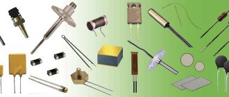
Variable resistors, also called rheostats or potentiometers, are designed to gradually regulate current and voltage. They look like this:
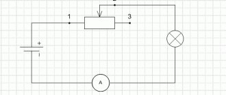
The difference is that a rheostat regulates the current in an electrical circuit, and a potentiometer regulates voltage. On radio circuits, variable resistors are designated by a rectangle with an arrow attached to their body.
Read also: Maybelline eyebrow pencil
In the diagrams, numbers 1 to 3 indicate the location of the resistor outputs.
Mechanical varieties
We continue to study the potentiometer. Let's look at what this is mechanically next. The device is a current regulator equipped with a rotary-type controller. The keys are resistive type, there are two terminals, the through resistance can withstand up to 3.5 Ohms. The maximum linear distortion is 90 dB, the maximum negative voltage is 3.5 V.
It is worth noting some features of this type of device, namely:
- The type of resistors is open.
- Rheostatic mode is mostly absent.
- The permissible positive voltage is 2.4 volts.
- Case marking – PP-20 or T23.
- The average cutoff frequency is 2400 kHz.
The mechanical model is excellent for reverse control, and the bandwidth depends on the switch parameters.
Classification of rheostats and requirements for them
Rheostats can have different purposes and, depending on it, are divided into load, starting, regulating, starting and excitation rheostats .
To reduce dimensions, starting rheostats and their starting part must have a large time constant. As a rule, there are no special requirements for the stability of the operating resistance. Such rheostats are designed to operate in short-term mode. The interval between starts cannot be less than twice the start time to restore the rheostat temperature.
Other types of rheostats are subject to strict resistance stability requirements. They must be designed for long-term operation. Rheostats with metal resistors are most widely used in electric drive power circuits. Cam, flat and drum controllers are used for switching.
According to the cooling method, rheostats are divided into air, oil, and also with forced water or oil cooling.
The meaning of the word Rheostat according to the Brockhaus and Efron dictionary:
Rheostat is the name of a device used to measure the electrical (or galvanic) resistance of a conductor. The device was first described under this name by Wheatstone in 1843. A similar device (agometer), independently of Wheatstone, was constructed by the Russian academician Jacobi. This latter was then improved by E. H. Lenz. The measurement method using these instruments is based on the introduction of a thin nickel-silver wire of a known length into a given galvanic circuit. This wire is wound around a marble cylinder, with one end communicating with the metal axis of the cylinder. When the cylinder rotates, either part of the wire is wound onto another metal cylinder (Wheatstone), or a metal wheel moves along the wire (Jacobi), or the cylinder itself moves along its axis, and the wheel remains in place (Lenz). N.A.G.
How does a rheostat work?
A rheostat is a controlled variable resistance that can change the current parameters in an electrical circuit.
As a result of a large number of experiments and scientific and technical research, various models of rheostats appeared, such as:
- wire;
- slider;
- liquid;
- lamp.
Wire
This is the simplest rheostat. It consisted of high resistivity wire stretched over a frame. It passed through several connectors at once. By switching on one or another contact, they achieved a change in the length of the conductor. Thus, the required resistance value was obtained, therefore, the parameters of current and voltage in the electrical circuit were changed. The disadvantage of such a device was the limited length of the conductor and, accordingly, the range of changes in current characteristics.
Read also: Why do you need a quadcopter?
Slider
A slider device is a classic rheostat design. RS is an elongated coil that looks like a cylinder of dielectric material with a wire wound on it, covered with scale. A slider moves progressively along the rod, which touches the coil spiral with its contacts. The device is connected to the electrical circuit at two points: this is the contact of the slider and one of the ends of the coil.
Liquid
The device is a container filled with electrolyte, into which two electrodes in the form of metal plates are immersed. The resistance of the current flowing through the electrolyte depends directly on the gap between the electrodes and is inversely proportional to the surface area of the electrodes.
Lamp
The resistance in the circuit is regulated by the number of incandescent lamps connected in parallel. This is not a very good solution. Adjusting current parameters is expensive due to the large waste of electricity consumed by incandescent lamps.
Important! All of the above devices are long gone, except for the slider rheostat. They were pioneers in the field of adjusting electrical current parameters. They were replaced by economical and compact variable resistors. Despite this, the principle of operation of the devices remains the same.
What is the difference between a potentiometer and a rheostat?
In one of the previous articles we discussed the main aspects related to working with resistors, so today we will continue this topic. Everything that we discussed earlier concerned, first of all, constant resistors , the resistance of which is a constant value. But this is not the only existing type of resistor, so in this article we will pay attention to elements with variable resistance .
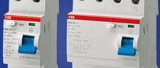
Rheostat for car interior heating stove
The car's heater itself, when turned on, is at a static heating level. The level of air temperature in the cabin depends on the speed of rotation of the fan rotor. A rheostat built into the fan power circuit changes the speed of the hot air flow through manual control.
There are combined systems for heating the car interior. This is when the degree of heating of the air flow is regulated by two rheostats: the stove itself and the fan.
Car heater rheostat
Additional Information. A typical cause of failure of the interior heating system is often a blown fuse. The breakdown is eliminated by re-soldering the electrical part.
Sensors based on rheostats
The voltage, current in the operating circuit, the position of the slider in the rheostat and the resistance it provides are directly dependent.
This feature forms the basis of the rotation angle sensor. In such a device, a specific electrical quantity corresponds to a specific rotor position. Currently, such sensors are being replaced by improved optical and magnetic analogues. The reason for this is the instability of the dependence of resistance and angle in relation to the temperature effect. The gradual displacement of rheostat-type sensors is also due to the transition to digital, more convenient systems. Today, resistive meters are used in circuits where analog signals are present.
Knowing why electric rheostats are needed, one can easily explain their widespread use in the automotive industry, technology, and industry. Resistance is necessary for the operation of radio equipment; when starting electric motors, they are used in the form of an active load. The failure of a small device can lead to a failure of the entire system.
This is the importance of rheostats
Oil cooling
Metal rheostats with oil type cooling increase the heat capacity and heating time due to the good heat conductivity of the oil. This makes it possible to increase the load in short-term mode and reduce the consumption of resistor material and the size of the rheostat itself.
Elements that are immersed in oil must have a large surface area to ensure good heat transfer. If the resistor is a closed type, then there is no point in immersing it in oil. The immersion itself protects the contacts and resistors from environmental factors. In oil, the breaking capacity of the contacts increases. This is the advantage of rheostats of this type. Thanks to lubrication, large pressures on the contacts are possible. But there are also disadvantages. This increases the risk of fire and contamination of the premises.
A rheostat can be included in the circuit as a variable resistor or potentiometer. This ensures smooth adjustment of resistance and, as a result, regulation of current and voltage in the circuit. They are often used in laboratories.
EP models
A device of this brand, index 1200, is connected via a pair of pins. The potentiometer sensor can withstand four cycles with a cutoff frequency of up to 2300 kHz. The modification is suitable for adjusting the sound and timbre of guitars, and is also used as an element of computer technology.
EP-3000 is characterized by a small spread of resistance. The rheostat-type key is located near the terminals, the housing has special protection. There is a software sampling option, calibration is performed using bridge circuits, and one resistor is provided. This version is not suitable for setting filters and adjusting gain.
Modification EP-2110 is used for digital reverse control. There is a rheostatic switch, a pair of pins in the lower part of the case, and software sampling. The configuration is performed automatically without the participation of bridge circuits.
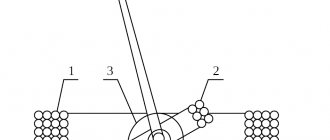
Rheostatic sensor elements
The sensor consists of the following elements:
- Frame 1.
- Resistance in the form of winding, which consists of wire 2.
- Movable brush 3, which will slide along the surface of the rheostat.
Rheostat sensors come in 2 types:
- With stepless multi-turn winding.
- With sectional winding.
In sensors that have sectioned resistance, a stepwise change in resistance will occur during brush movement. If the sensor has stepless winding, then in this case the change in resistance will be smooth.
Modifications
To find out more precisely what a potentiometer is, a review of some device models will help. First, let's look at the Skal modification. In this series, models under the index 103, 105, 107 are especially popular.
Brief description of devices:
- Skal 103 is a device designed to adjust resistance in an alternating current circuit. This device features exclusively movable contacts. There is one key, a passive resistor, placed near the terminals. A software sampling function is provided; there is no rheostatic mode. The housing marking is P20, the potentiometer is adjusted by levels.
- Model 105 is an automatic device used in AC systems. A passive type resistor is installed, the key is located near the terminals. The modification is optimally suited for computers because it has a high cutoff frequency and a linear distortion parameter of 56 dB.
- Option 107. This device has a level frequency of 2400 kHz, a resistive switch, and passive resistors located in the lower compartment of the case. Its marking is PP21, the maximum lowering band is 2.3 microns, there is a rheostat mode.
Why do you need a PC?
Based on what a rheostat is needed for, variable devices are divided into the following types:
- ballasts;
- launch RS;
- ballasts;
- load devices.
Ballasts
Rheostats are used in the control system of DC electric motors. With alternating current, the RS is included in the power supply circuit of asynchronous motors with a phase rotor.
Launcher PCs
Their main purpose is to reduce the inrush current during the start of the electric motor. Also, such rheostats work in regenerative rheostatic braking systems. It is needed to smoothly reduce the rotation speed of the rotors of electric motors and generators.
Ballasters
Ballast DCs quickly absorb the energy that is released during sudden braking of the electric motor. That is, ballast is discharged in the form of excess electricity.
Load devices
PCs of this type create additional load in the electrical circuit. This is necessary to maintain the necessary processes associated with the operating mode of various devices, engines and other devices.
How the device is connected to the network
The device is connected to the circuit in two ways: in series and in parallel. When connected in series, the resistance of the equipment adds up. The total resistance will be greater than any individual resistance.
The diagram of electrical circuits, where rheostats with parallel connection are designated, looks like this:
With such a connection, the reciprocal values of the resistance are added, i.e. The total conductivity consists of the conductances of each component.
The presented drawings are intended for the simplest equipment. The more elements they include, the more complex the device created on their basis.
- Why is a rheostat used in an electrical circuit?
- Cable insulation resistance standards - table
- Instructions for rewinding electric motors with your own hands at home
What is a rheostat, principle of operation
- What is a rheostat, principle of operation
- Main purpose of the device
- Metal rheostats
- Oil cooling
- Starter rheostats
- Design and principle of operation
Rheostats are two-pole variable resistors that are configured to use only one end contact and only the wiper contact.
The unused end terminal can either be left unconnected or connected directly to the wiper.
These are wire-wound devices that contain dense turns of heavy-duty enameled wire that change resistance in steps.
By changing the position of the wiper on the resistive element, the amount of resistance can be increased or decreased, thereby controlling the amount of current.
The rheostat is then used to control the current by changing its resistance value, turning it into a true variable resistor. A classic example of the use of a rheostat is in controlling the speed of a model train set or Scalextric, where the amount of current passing through the rheostat is controlled by Ohm's law. Rheostats are then defined not only by their resistive values, but also by their power control capabilities as P = I 2 * R.
How does a potentiometer affect a motor?
Often, owners of modern cars try to squeeze maximum power out of the car by pressing the accelerator pedal all the way. This solution is not successful, since the aggregation between the power unit and the gas pedal occurs through a special throttle sensor (potentiometer). Mercedes, BMW, Volkswagen and most other foreign cars are equipped with a similar device.
The device is designed to regulate the supply of fuel to the engine in dosed portions. In addition, the device monitors the dynamics of pressure on the accelerator pedal and determines the idle speed. The components of a potentiometer for a car are two resistors, one of which is a stable type, the second is a variable analogue. The total resistance of the elements is 8 kOhm.
Where are rheostats used?
The main purpose of a rheostat is to regulate the current in an electrical circuit.
There are various types of rheostats, but in technology, for example in electric vehicles, current regulation by rheostats is being replaced by other, more profitable electronic regulators, semiconductor elements and potentiometers. The fact is that by changing the current in the circuit, the rheostat heats up, which consumes significant energy. If the current is high, the rheostat wire may overheat and the rheostat will stop working. In electronic regulators these losses are hundreds of times less.
- A rheostat is typically used in areas where high voltage or current is required. Microwave, refrigerator, mixer, fan, power tools, etc.
- Dimmers use rheostats to change the intensity of light. If you increase the resistance of the rheostat, less electric current will flow through the light bulb and the brightness of the light will decrease. Likewise, if we decrease the resistance of the rheostat, more electric current flows through the light bulb and the brightness of the light increases.
- Rheostats are used to increase or decrease the rotation speed of an electric motor.
- It is used in switches that set the temperature on electric stoves. It is used in all devices similar to kitchen appliances that have heating elements whose temperature must be increased or decreased.
- It is used to increase or decrease the volume in devices such as TV, radio.
General information
Electric current is the movement of free charged particles under the influence of an electromagnetic field. Any substance consists of atoms that form a crystal lattice using covalent bonds. When an electric current flows through a conductor, its particles interact with the nodes of the crystal lattice. Charge carriers have kinetic energy (Ek), which depends on the mass of the particle (m) and its speed (V3). It is determined by the formula: Ek = m * sqr (V3) / 2 .
When particles collide with nodes of a crystal lattice, a complete or partial transfer of energy to the atom occurs.
However, the energy potential of the free charge carrier is restored, since it is constantly affected by the electromagnetic field. The process of interaction of particles with atoms is repeated a certain number of times until the influence of the electromagnetic field stops or the particle passes completely through the conductor. This physical phenomenon is called electrical resistance or conductivity. The last value is the reciprocal of the resistance. Resistance is designated by the letter “R”, and conductivity by “G”.
The unit of resistance is Ohm. It is calculated using certain formulas or measured with an electronic measuring device called an ohmmeter.
Physical dependence
The value of R depends on the number of free charge carriers, the number of which is determined based on the electronic formula of the substance. It can be determined from the periodic table of chemical elements by D.I. Mendeleev. Substances are classified according to conductivity as follows: conductors, semiconductors and insulators (non-conductors).
Conductors include all metals, electrolytes and ionized gases.
In metals, charge carriers are free electrons, in electrolytes - anions and cations, and in ionized gases - electrons and ions. Semiconductors are capable of conducting electrical current under certain conditions. In semiconductors, free electrons and holes are charge carriers. Insulators or dielectrics are not capable of conducting electricity because there are no free charge carriers in their structure.
The quantity that determines the type of material and its ability to conduct is called resistivity (p). There is also an inverse value regarding resistivity. It is called conductivity (σ) and is related to p by the following formula: p = 1/σ . When performing calculations, it is necessary to take into account the dependence of the electrical resistance of the material on other physical quantities or factors, which include the following:
- geometric components;
- electrical quantities;
- temperature indicators.
These three groups of factors must be taken into account when manufacturing rheostats, resistors and other resistive load elements. During repair and design of devices, all factors should also be considered, since incorrect calculations can lead to failure of the radio equipment.
You may be interested in this Measuring device Ts-20
Material geometry
The geometry of a conductor (semiconductor) includes its length (L) and cross-sectional area (S). The value of S can be calculated using an abstract algorithm that is suitable for all forms of conductors and semiconductors. It looks like this:
- Visually determine the shape of the cross-sectional figure (circle, rectangle or square).
- Find in reference books or the Internet a formula for finding the cross-sectional area of a figure.
- Measure the necessary geometric parameters (for example, diameter) and substitute them into the formula.
- Perform mathematical calculations.
If the conductor is stranded (consists of many conductors), then the cross-sectional area of one conductor should be calculated and then multiplied by the number of conductors. Based on everything, we can deduce the dependence of the resistance value on the type of substance, length and cross-sectional area of the conductor: R = p * L / S.
The physical meaning of the dependence is as follows: an electric current moves through a conductor, the type of which is determined by the parameter p, and its particles pass through a certain length L with a cross-section S (with a small cross-sectional area, more frequent collisions of electrons with nodes of the crystal lattice occur).
However, geometric parameters are not the only factors influencing the conductivity value of a material.
Influence of electricity parameters
In order to take into account the influence of current and voltage on R, you should pay attention to Ohm's law. He has two formulations used for calculations: for the complete chain or its section. Ohm's law for a complete circuit shows the dependence of the current value (i) on the electromotive force (e) and the value of R, consisting of the sum of the internal (Rinternal) and external (Rexternal) resistances.
The variable Rinternal is the internal resistance of the power source (generator, battery, transformer, etc.). Rext is the resistance of all consumers of electrical energy and connecting wires. Ohm's law for a complete circuit connects all these quantities with the following relation: i = e / (Rexternal + Rinternal) . The value of Rext is determined by the formula: Rext = (e / i) - Rint .
For a section of a circuit, the relationship for finding the resistance is simplified, since the EMF and Rinternal are not taken into account. This law shows a directly proportional dependence of the current (I) on the voltage (U), as well as inversely proportional to the resistance value R: I = U / R. In some cases, these factors may not be enough for accurate calculations, since there is another dependence - the temperature indicators of the material.
Effect of temperature on conductivity
Resistivity affects the conductivity of a material, but it depends on temperature. To prove this hypothesis, you need to assemble an electrical circuit consisting of the following components: an incandescent lamp, a power source (12 V), a piece of nichrome wire and an ammeter. Any power source can be selected.
You might be interested in Multimeter probes
It is important that the voltage value is not higher than the nominal value of the potential difference of the lamp, i.e. the battery is 12 V, and the lamp must also be 12 V. The circuit elements are connected in series. It is recommended to place a piece of wire on a refractory brick, since when electric current flows through the nichrome, it will heat up.
An ammeter is needed to monitor current values that will change over time. The lamp is a light “signaling device” that allows you to visually observe an increase in resistance. The brightness of its glow will gradually fade. When current flows through the circuit, Ohm's law is visually confirmed for a section of the circuit. As R increases, the current decreases. The dependence of resistivity p depends on the following variables:
- Table value of resistivity (p0), calculated at a temperature of +20 degrees Celsius.
- Temperature coefficient "a", which for metals is considered greater than 0 (a > 0), and for electrolytes - less than 0 (a < 0).
The tabulated value of p0 can be found from special electrical reference books or from the Internet. The dependence of p on temperature is described by the following relation: p = p0 * [1 + a * (t - 20)] . If necessary, you can substitute p into the formula for the dependence of R on length and cross-section: R = p0 * [1 + a * (t - 20)] * L / S.
It makes no sense to perform exact resistance calculations, but these features should be taken into account when manufacturing and repairing various devices.
Resistance should be measured with an ohmmeter, but professional radio amateurs recommend using a multimeter. It is combined and allows you to measure not only resistance, but also current and voltage. There are models that can measure frequency, test semiconductor devices, etc.
Principle of operation
The principle of operation of the PC can be considered using the example of the operation of a slider device. The slider moves along the coil across the winding turns. On the sides of the ceramic cylinder there are two posts that support the horizontal rod. The slider is put through a hole in the housing onto this horizontal axis, along which it moves freely.
What is potential in electricity
The slider rubs against the coil turns with two metal plates. Current cannot pass directly through the turns, but only in a spiral. Consequently, only that part of the coil that is located between the input contact and the slider can work. This solved the problem of limited length of the wire RS conductor.
The closer the contactor is to the input contact of the coil, the lower the resistance of the PC. As a result, the voltage decreases and the current in the electrical circuit increases. Voltage is applied to the entire length of the winding, and the operating current is removed by the contacts of the slider. The contactor basically divides the PC into two series-connected resistors.
Note! The rheostat in the diagram is designated as a rectangle with an arrow. The geometric shape is a reel, and the arrow represents a slider.
Rheostat designation on the electrical circuit
Manufacturing materials
What is insulation resistance measurement and why is it important
Rheostats are divided into 4 types based on the type of material they are made of. These are carbon, metal, liquid and ceramic RS:
- Carbon devices include models where a graphite rod acts as a variable resistance.
- A metal example of execution can be slider rheostats. They have a variable resistor - a coil of metal wire.
- Liquid variable resistances are used to control the operation of electric motors in explosive atmospheres.
- Ceramic rheostats include toroidal devices. Their device is described above in the text.
Types of rheostats
The type of rheostats depends on their main purpose:
- Starting rheostats are designed to start electric motors with direct or alternating current;
- Starter rheostats are not only designed to start DC motors, but also to regulate the current;
- Ballast rheostats, also called load rheostats, absorb energy that is necessary to regulate the load on electric generators, i.e. create the required resistance in the electrical network;
- Excitation rheostats are used in electrical machines to regulate direct and alternating current; they absorb excess energy;
- A special group includes rheostats designed to divide voltage; they are called potentiometers. They allow you to use different voltages in one device without using additional devices such as transformers and power supplies. In this case, the rheostat has 3 terminals, where the lower terminals are used for current input, and the upper and one lower terminals are used as output. The voltage is adjusted by moving the slider.
Thanks to the use of rheostats in electrical appliances and machines, there is a reduction in electrical current surges and motor overloads, this, in turn, increases the service life of electrical appliances.
The rheostat on the electrical diagram has its own special designation.
Electronic options
The electronic damper potentiometer is a reversible type, often used as a volume control. The device is mainly equipped with two keys, supports about ten cycles, and has a software sampling option.
The devices under consideration often become elements of computing devices. The cutoff frequency limit is about 3,000 kHz. Many parameters depend on the design features and manufacturer. Linear distortion is about 80 dB, key skip is 3.5 microns. These devices are not intended for gain adjustment.
Types according to the “cone” - the nature of the change in resistance
“Cone” or “law” is the relationship between resistance. and the position of the scraper. Manufacturer controlled. Any ratio is possible, but for most tasks linear and logarithmic PTs (“sound cone”) will suffice.
A letter code may be used, but this is not standardized; it may be different for different manufacturers, but usually the marking is as follows:
How to measure the resistance of a resistor
Any resistor has resistance. For those who don’t know what resistance is and how it is measured, read this article as a matter of urgency. Resistance is measured in Ohms. But how do we find out the resistance of the resistor? There are direct and indirect methods.
The direct method is the simplest. We need to take a multimeter and simply measure the resistance of the resistor. Let's take a look at what this all looks like. I take a multimeter, set the knob to measure resistance and touch the resistor terminals.
resistance measurementI took a 1 kOhm resistor. He showed me 976 Ohms, which in principle is also normal, since such resistors always have some error.
The indirect measurement method is that we will calculate the resistance of the resistor through Ohm's law.
resistance formula through Ohm's law
Therefore, to find out the resistance of the resistor, we need to divide the voltage at the ends of the resistor by the current that flows through the resistor. It's quite simple!
Let's say I want to know the resistance of a light bulb's filament when it emits light. I think some of you are aware that the resistance of a cold tungsten filament and a hot one are completely different resistances. I can’t measure a red-hot tungsten filament of an incandescent lamp with a multimeter in resistance measurement mode, right? Therefore, this formula comes in handy for us
Let's find out by experience. I have a laboratory power supply that immediately shows the voltage and current that flows through the load. I take a lamp, set the voltage on the power supply, which is written on the lamp itself, and connect it to the terminals of the power supply.
incandescent lamp current consumption
So, it turns out that the voltage at the lamp terminals is now 12 Volts, and the current that flows in the circuit, and therefore through the lamp, is 0.71 Ampere.
We find that the resistance of the hot filament of the lamp in this case is
Basic division of potentiometers:
a) the nature of the change in resistance:
- linear (indicated by the letter A) – the change in resistance is directly proportional to the angle of rotation of the sliding contact;
- logarithmic (denoted by the letter B) - the change in resistance occurs quickly from the beginning, then slows down;
- exponential (denoted by the letter C) - the change in resistance occurs slowly at the beginning, then accelerates. Please note that sometimes the potentiometer type designation (letters A, B, C) may be different depending on the manufacturer of the potentiometer, so you should check this with the technical description of the specific unit.
b) body type:
— mounting (for soldering to the board);
— reversible stationary (placed on the body);
| Type | Description | Application |
| Single-turn | The engine rotates one revolution (approximately 270 degrees or 3/4 of a full revolution) | Most often, such potentiometers are used in devices where one revolution is enough to make adjustments. |
| Multi-turn | The resistor motor can be rotated multiple times (mostly 5, 10 or 20) to improve accuracy. In them, as a rule, the resistive element has a spiral or screw shape. | They are used where high accuracy and resolution are required. Multi-turn potentiometers are often used as trimmers on a printed circuit board. |
| Twin | Combines two separate resistors on one shaft, allowing parallel adjustment of two channels. The most common potentiometers are linear and logarithmic resistance. | It is used, for example, in stereo audio volume controls or other devices where it is necessary to simultaneously adjust two independent channels. |
— slider (linear);
| Type | Description | Application |
| Slider potentiometer | Single slide linear potentiometer is mainly designed for audio devices. High quality resistors are often made from conductive plastic. | For one channel |
| Dual slide potentiometer | The double potentiometer, as well as the double reversible potentiometer, allows you to adjust two independent channels. | Often used to control stereo in professional audio systems and other devices where it is necessary to control two channels simultaneously. |
| Multi-turn slide potentiometer | It has a spindle that converts rotational motion into translational linear movement of the potentiometer slide along the resistive element. | Used where high accuracy and resolution are required. A multi-turn slide potentiometer is used as a trimmer on a printed circuit board, but not as often as a rotary multi-turn potentiometer. |
Potentiometer design
A potentiometer most often has 3 terminals: two terminals are connected to each other by a constant resistance, the third terminal has a movable contact that moves along a surface of constant resistance.
Physical entity
Scientists' study of electricity led to the understanding that there is something that prevents free charges from passing through matter. The ability of a body to pass electric current through itself was called electrical conductivity. As it turned out later, it is determined by the number of free charges present in the structure of the element, the nature of the external influence and the physical dimensions of the body. All existing substances were divided into three types:
- conductors;
- semiconductors;
- dielectrics.
The first group included materials, when passing through which the value of the electric current practically does not decrease. These are all metals and electrolytes. The second includes elements whose conductivity changes significantly when exposed to external factors, such as temperature, light, and electromagnetic radiation. For example, silicon, germanium, selenium. Dielectrics are substances that almost completely absorb the energy of electrons, that is, convert electrical power into thermal power. Prominent representatives of this group are: rubber, plastics, composite materials (textolite, getinax, vtoroplast).
This word comes from the Latin resisto, which literally translated into Russian sounds like “I resist.” Its correct definition, which can be found in specialized literature, is as follows: “A resistor, or resistance, is a passive radio component in an electrical circuit, characterized by a constant or variable conductivity value. It is designed to convert current into potential difference or vice versa.”