What are the types of control devices?
Motor controls are essential to building your robot. Now the robot design, actuators or motors and controller for the robot have been selected. It's finally time to get things moving. The first question many beginners ask when building their first robot is “how can I control the motors?”
Motor control devices such as a motor controller are used for this purpose. After doing a little research on the term "motor controller" many questions arose. What is a motor controller and why do I need one?
Vector asynchronous motor control, application and methods
To understand what “vector” control is, it is the reaction of a turning device with the so-called “spatial” vector, which rotates at the frequency of the engine sphere. And in order to better understand all its functions, it is advisable to review the article and find the necessary information.
An asynchronous motor is a motor of variable flow, where the energy in the stator windings creates a rotating field of magnets. Such a field induces currents in the winding of the rotor, affects the operating currents, attracting the rotor into operation.
However, in order for the rotating magnetic sphere of the stator to induce currents in a working rotor, the rotor in the hardware spinning is forced to be slightly behind the spinning of the stator. Consequently, in a non-synchronous motor, the speed of rotor circulation is constantly approximately the same as the speed of rotation of the magnetic field (which is caused by pulses of unstable current, which is why the motor is powered). When the rotor's departure from the moving magnetic field of the stator is greater (rolling), a heavy load will therefore be created on the motor.
A lack of synchronism between the torsion of the rotor and the magnets in the stator is a normal feature for an unstable motor, which is where its name comes from. The rotating magnets in the stator are formed using coils powered by flows that are in phase.
Naturally, for the sake of this mission, a 3-phase unstable current is adapted. There are also single-phase asynchronous motors, in which the progression of phases among the currents in the windings is formed by connecting all sorts of resistances in the windings. To carry out high-quality adjustment of the angular speed of rotation of the rotor, and also the rotation factor on the shaft of current brushless motors, they use either vector or scalar control by an electronic drive.
Vector control is a method of controlling brushless motors of unstable current, which allows you to independently and, in principle, inertia-free coordinate the speed of rotation and the torque on the electric motor shaft.
The key idea behind vectorial movement is to check not only the magnitude and impulse of the feeding force, but also the phase. In other words, the value and angle of the plastic vector are tested.
Advantages of vector control:
- highest reliability of speed control;
- smooth start of movement and smooth motor handling across the entire frequency spectrum;
- rapid suppression when changing the load: when the overload changes, there is absolutely no change in speed;
- enhanced range of management and punctuality of regulation;
- heating leaks and magnetization are reduced, and the efficiency of the electric motor increases.
The disadvantages of vector control include:
- the need to adjust motor parameters;
- huge swings of rapidity under long-term load;
- high computational complexity.
The following methods of adjusting an asynchronous motor are used: ·
- rheostat - modification of the transmission of rotation of an asynchronous motor with a wound rotor by replacing the resistance of the rheostat in the rotor circuits, and in addition, this makes the starting torque larger and increases the decisive slip; ·
- frequency - reversal of the circulation pulses of an asynchronous motor by changing the conductivity of the flow in the supply voltage, due to which this helps to modify the repeatability of the rotation of the stator field. The motor is introduced through a conductive reformer;
- reconnection of the windings using a “star” to “triangle” circuit during engine startup, which creates a threefold reduction in the starting currents in the windings, but it also helps to reduce the torque; ·
- pulsating feed - power supply of a specific option (for example, sawtooth); · the establishment of an auxiliary EMF is harmonious or oppositely directed with the slip frequency into the secondary circuit; ·
- changing the number of poles, if such a reversal is reasonably foreseen (only on squirrel-cage rotors);
- replacement of the amplitude of the supply voltage if only the amplitude (or influencing value) of the swirling flow is modified. Further, the control and excitation voltage vectors remain perpendicular (autotransformer starting); ·
- phase control is characterized by the fact that the reversal of the rotor spinning impulses is created by changing the advancement of the phases between the vectors of excitation and control forces. ·
- amplitude-phase reception covers the two described methods; ·
- investment in the reactor stator power supply apparatus; ·
- inductive reaction on a wound-rotor motor.
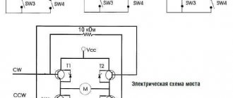
Electric scheme
The basis of the circuit is the outline of the control of magnetic flux coupling and circumstances together with the evaluation unit, which can be used in a variety of ways. This means that the outer speed control loop is highly unified and generates speed control signals to adjust the M* factor and magnetic flux linkage* (via the flux control source). The speed of the motor can be measured using a meter (speed / position) or can be done through an assessment, which allows you to create sensorless control.
Classification of vector control technologies
Only the most famous control technologies are discussed here. The discussed methods for controlling the factor are presented for control systems for asynchronous motors and synchronous motors with long-term magnets with sinusoidal return EMF.
Most often, torque control methods are divided into the following types:
- Linear (PI, PID) regulators;
- Nonlinear (hysteresis) regulators.
- No return communication.
- There is feedback.
- In an established order.
Vector regulation details
To get rid of the disadvantages, back in 1971, Siemens engineers recommended using vector guidance in the tool, during which control is executed with feedback of values in the flow. The initial arrangements of the vectorial direction contained detectors in the instruments. Now the approach to this method is quite different:
- An exact sample of the motor allows one to analyze the speed of rotor circulation and the gross torque from the initial stage of the existing phase currents (from the repeatability and number of currents in the stator windings).
This more conscious approach helps to create an independent and almost inertia-free coordination of both the shaft moment and the speed of shaft circulation on the pressure force, since flow phases are provided during control. Some more executive systems of vector control are equipped with fundamental methods of feedback on the force of movement, and control systems without speed meters are called sensorless.
In connection with the areas of use of any of the electric drives, their vector control technique will have to have its own characteristics, as well as some required level of accuracy for control. If the conditions for actual speed regulation allow a slope of 1.5%, and the scale of regulation is no higher than 1 to 100, then the sensorless design will be absolutely perfect. When accuracy of speed adjustment with a shift of no more than 0.2% is required, and the spectrum is combined to 1 in 10,000, then the existence of a feedback connection via the speed meter on the shaft is important.
The presence of the rapidity connector in the vector control examples allows the start to be perfectly coordinated even at low conductivities up to 1 Hz. Well, vectorial control delivers the benefits it deserves. The highest precision in regulating the speed of rotation of the rotor (and without a speed meter on the device) in conditions of movably replaceable overload on the shaft, so jerks are not expected. Easy and direct shaft handling at low speeds.
High efficiency for low losses in the normal environment of these power supplies. Vector control also has its disadvantages. Computational entanglement. The need to create initial parameters (for example, a controlled drive).
For a quantitative electronic drive, vectorial control is not suitable; here, scalar control will be preferably used.
The result occurs due to the phenomenon of circulation currents in the cylinder. Since it seems in the law of electromagnetic induction discovered by Faraday, to replace the flux of magnets with an isolated silhouette in the middle is the emf or voltage. This meaning, applied to a copper cylinder, instantly activates the origin of current in the cylinder.
Also, this current also organizes its own, counter electromagnetic flow, concentrated directly to the other side from the replacement of the magnet flow:
- The high-frequency current appearing in an isolated shorting circuit has a similar side of motion that the magnetic field it creates acts as a resistance to this change in the magnetic flux that was activated by this current.
- The closed outline resists the change in magnetic flow in the instrument.
- If you quickly place a magnet on a copper cylinder, then a bold modification of the magnetic flow occurs, so similar counter-currents will flow in the cylinder, then the magnetic sphere in it at the beginning of movement will be equally zero: the magnetic field of the adjacent magnet will be absolutely compensated by the magnetic currents of the cylinder.
When the magnet is presented and held, the energy in the cylinder, due to the presence of the functional resistance of copper, will slowly decrease, and the field of the cylinder, organized with flows, will disappear: the magnetic flow of a long-term magnet will “break out” inside the cylinder, as if the cylinder does not exist at all. You just need to try to hide the magnet, then the cylinder will respond again - only now it will perhaps be able to independently “recreate” the disappearing electromagnetic flux in the middle of the body, then at first it will resist replacing the magnetic flux, in such a situation and its disappearance.
What does it mean to “recreate electromagnetic motion”?
Therefore, it is known that for a certain period of time, the wind cylinder can be considered a symbolic “continuous magnet” - a turbulent current moves in the unit, causing a magnetic field (with this type, superconductors “hang” in a magnetic field). The rotor of an asynchronous motor, with a “squirrel cage” appearance, with a current from one of the “frames” of the squirrel cage responds to an increase in the external magnetic field.
Vector sensor design of discontinuous motor guidance
The caretaker contains evidence from the rotor location sensor, and leaking stator fluids in the axes, . At the end of the contemplator is the location of the rotor “magnet”, the actual angle of the contemplative flux clutch of the rotor. In the remaining ones, the design is absolutely similar to a similar scheme assigned to a continuous tool, only the d, q axes are rewritten to x, y, and the x axis is assigned a flux assignment that can be assisted by a “magnet” in the rotor. In addition, an “s” indicator has been added for many values to make it clear that only the value provided places the position towards the stator, instead of the rotor.
What happens? The rotor magnet always slides due to its location on the rotor on the edge of the y-axis. The stronger the current, the more powerful the sliding. The viewer in the present period calculates the location of a given magnet and “adjusts” the x, y axes all the time forward tangent to the d, q axes (the location of the rotor). The x-axis constantly fits the current location of the flux linkage in the rotor - the location of the "magnet". The x, y axes always move (in motor effort) a little faster than the rotor is spinning, eliminating slipping.
The energy in the rotor, if measured or simulated, comes out sinusoidal. These devices are exclusively modified without the conduction of stator flows, but with the presence of pulse slips, that is, infinitely slowly. When the industrial intermittent stator is 50 Hz, then when the load mode is switched on, the harmonic in the rotor is small hertz values.
Why is vector control with an asynchronous engine better than scalar control?
Scalar guidance is if the force of the established conductivity and amplitude is adapted to two-speed engines - for example, 380V 50Hz. And due to overload for the rotors, this does not affect the operation in any way - without current regulators and so on... The radio frequency of the force and this amplitude are simply set - scalar values, and the energy and flows in the engine are independently set, as they need.
In the created system of the motor product, vectorial control is indistinguishable from scalar control - vector control will undoubtedly also be presented at the same 380V, 50Hz even under normal load. However, transitional types are excluded... if it is necessary to quickly turn on an electric motor with a given torque, if it is necessary to develop a diagram, when there is a pulsating load, when it is necessary to generate heat, the electric generator regulation with the required degree of strength - scalar regulation either cannot perform such data, or does so with very poor , slow transient actions, which can also “knock out the protection” of reconfiguring pulses due to excess current or the force of the long-term current link (the engine swings and can jump into the power generator, for which the frequency device may not be prepared).
In the vector structure, “controlling”. The beginning of the movement is set by itself, and so is the flow. It is allowed to narrow it at the right stage so as not to exceed the laws of protection. It is possible to adjust and boost currents if it is immediately necessary to produce a significantly more powerful torque. It is possible to coordinate not only the start of the motor, but also the flow (x-axis current): when the overload on the motor is not great, then there is no reason to maintain the current in the rotor (to create an “optimal mode” magnet) - it is possible to relax it, making less loss.
It is necessary to regulate haste with the speed regulator with increasing punctuality and speed. It is important to use a non-simultaneous drive as a traction drive, giving it the required traction torque. In short, for heavy efforts with active motor output, vectorial control by an asynchronous motor is indispensable.
In addition, there are characteristic features of the vector control of an asynchronous mover from a synchronous one.
The first is a value measuring device. When, in order to carry out a simultaneous drive, it is important to understand the unconditional position of the rotor in order to know the position of the magnet, then such information is not needed in an asynchronous drive. The rotor does not have a certain defined pole system, the “magnet” slides there non-stop, but you can look at the control circuits for the rotor flux coupling, and there is also no need to reduce the position: only the harmonic of the rotor circulation is included in the switching methods. Therefore, it is possible to save money on the meter: an ordinary incremental encoder is sufficient to observe the ionization of rotation (possibly a tachogenerator), perfect position meters are not important.
The next step is motion control in an asynchronous motor apparatus. In a continuous machine with long-lasting magnets, the flow is not adjusted, which eliminates the highest frequency of motor rotation: it will not take force from the inverter. In a multi-time engine, sometimes this happens... you simply need to reduce the order on the x-axis and move on! The largest fluctuation is not limited. In exactly the same way, there are sensorless methods of vector control of an asynchronous motor, which evaluate the rotor flux angle as a non-working warning of the position (or speed) meter of the rotor shaft.
Literally the same as in continuous instruments, in the system of operability of such methods there are difficulties with low oscillations of the rotor rotation, in which the EMF of the motor is small. If with industrial asynchronous engines the work is done cheaper by installing a duralumin cage, then in traction, in which large-scale dimensions are more needed, the opposite will be true; a copper cylinder can be recycled.
Thyristor control
To control an asynchronous motor, it is important to use thyristors in combination with relay-contactor units. They are adapted as powerful ingredients and are part of the stator circuit; relay-contactor circuit breakers are connected to the control circuit. Thyristors are used as power connectors, it is allowed to apply force to the stator at startup to zero according to the common adverb, reduce the energy and moments of the box, implement effective braking or step-by-step operation.
To start the motor, it is connected to the interacting switch QF, presses the SB1 “Start” button, and as a result, contactors KM1 and KM2 are connected. On the moving cathodes of the thyristors, impulses are given, closed at 60 relative forces. A low power is applied to the motor stator, which makes the starting current lower and the starting torque as well.
Motor controllers
A motor controller is an electronic device (usually a circuit board without a housing) that serves as an intermediate device between the microcontroller, power supply or batteries, and motors.
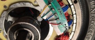
motor control device
The microcontroller (the brain of the robot) sets the speed and direction of the motors. But it cannot control them directly due to its very limited power (current and voltage). On the other hand, the motor controller can provide current at the required voltage. At the same time, it cannot decide how fast the engine should rotate.
So the microcontroller and motor controller must work together. In order for the motors to move as we need, electric motor control devices are used. Typically the microcontroller can command the motor controller on how to drive the motors using a standard and simple communication method.
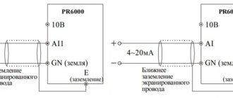
- For example, such as UART (Universal asynchronous receiver/transmitter or UART - universal asynchronous transceiver). This is one of the oldest and most common data transfer protocols.
- It is possible to use PWM (pulse width modulation - PWM).
- Additionally, some motor controllers can be controlled manually by an analog voltage, usually generated by a potentiometer.
The physical size and weight of the motor controller can vary significantly. From a device smaller than a fingertip used to control a mini sumo robot to a large controller weighing several kilograms. The weight and size of the motor controller usually has minimal impact on the robot.
Although it may be necessary to make a small robot or unmanned aerial vehicle. As a result, the weight and size of the controller can be critical. The size of a motor controller is usually related to the maximum current it can provide. The increased current also means that larger diameter wires must be used.
Schematic diagram
Its operation is based on a PWM pulse generator and triacs for regulating the operation of motors. The option is the simplest, it is often called classic. Two elements: D1 and R1 limit the magnitude of the supplied power voltage to safe levels. This is done in order to ensure the required level of power filtration. Components marked R3, R5, P1 act as voltage dividers with further possibilities for their adjustment. They occur when setting the power values supplied to the load.
When the resistor component R2, which is included in the supply circuit for the m/s phases, changes, the internal units are synchronized with a triac of type VT 139.
Types of electric motor controllers
There are several types of actuators (step 3). Therefore, there are several types of motor controllers.
- DC motor machine controllers. They are used with DC, DC gear motors and many linear actuators.
- Brushless DC motor controllers. Used with brushless DC motors.
- Servo Motors: Used for hobby servo motors.
- Stepper motor controllers. Used with unipolar or bipolar stepper motors depending on their type.
Control of brushed DC motors
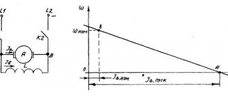
From the speed equation of a DC motor, it can be seen that the rotational speed of a brushed DC motor is directly related to the magnitude of the supply voltage applied to the motor and the load torque.
- where is the angular frequency, rad/s,
- U—supply voltage, V,
- – constant EMF, V∙s/rad,
- M — electric motor torque, N∙m,
- — mechanical rigidity of the engine.
Thus, the rotation speed of the brushed DC motor is changed by changing the magnitude of the supply voltage.
Selecting a Motor Controller
Motor controllers can only be selected after you have selected your motors, drives. Additionally, the rated current of a motor is related to the torque it can provide. Since a small DC motor does not consume much current, it cannot provide much torque. Whereas a larger motor can provide higher torque, but it will require higher current.
DC Motor Control
The first consideration is the motor voltage rating. DC motor controls typically offer a range of voltages. For example, your motor operates at 3V rating. Therefore, you should not select a motor controller that can only drive the motor between 6V and 9V. This will help you eliminate some motor controllers from the list.
So, you have found a number of controllers that can drive a motor with the appropriate voltage. The next consideration will be the DC current that the controller will need to supply. You need to find a motor controller that will provide a current equal to or greater than the rated current drawn by the motor.
If you select a 5A motor controller for a 3A motor, then the motors will draw as much current as required. On the other hand, a 5A motor will most likely drive a 3A controller. Many motor manufacturers provide DC motor cut-off current. As a result, this doesn't give you a clear idea of the motor controller you'll need. That is, you cannot find the constant operating current of the motor. In this case, a simple rule is to estimate the DC motor current to be about 20-25% less than the stall current.
All DC motor controllers provide maximum current. Make sure this value is approximately twice the motor's rated current. Note that when the motor requires more torque (for example, going up a hill), it requires more current. Choosing a motor controller with built-in cooling and thermal protection is a very good choice. Another important consideration is the control method.
PWM motor control
Motor control devices use the following methods:
- analog voltage
- I2C (IIC interface bus)
- PWM (Pulse Width Modulation - PWM)
- R/C (Radio Control, radio control)
- UART (Universal Asynchronous Receiver)
If you are using a microcontroller, check what types of connections you have and which motors are compatible for you. If your microcontroller has serial pins, you can choose a serial motor controller. For PWM you will probably need one PWM channel per motor.
Control methods
In practice, it remains to choose which motor controller is needed - single or double. Dual DC controller can control the speed and direction of two DC motors independently. Finally often saves you money (and time).
The engines do not have to be identical. Although for a mobile robot, the drive motors should be the same in most cases. You need to choose dual motor controller based on more powerful DC motor.
Please note that the two motor controllers only have one power input. Because if you want to control one motor at 6V and another at 12V, it will not be possible. Please note that the effective voltage is always maintained on each channel. Standard servo motors are designed to use specific voltages for maximum efficiency. Most operate from 4.8V to 6V and their current draw is similar, the selection steps are somewhat simplified.
However, you may be able to find a servo that operates at 12V. That being said, it is important to have additional information about the controller if your servo is not considered a "standard" servo. Also most hobby servos use a standard R/C servo. These are three wires which are ground, voltage and signal.
Now you need to choose a control method. Some servo controllers allow you to control the position of the servo manually using a set of buttons/switches. Others are via UART (serial) commands or other means. Determine the number of servos to be controlled.
Controllers can control many servos (typically 8, 16, 32, 64 and above). You can, of course, choose a servo motor controller that can control more servos than you need. Like DC motor controllers, the control method is an important factor.
Stepper motor control
Which motor did you choose - single-pole or double-pole? Select your stepper motor controller type accordingly, although almost all motor controllers can control both types. The number of wires usually helps determine the type of motor. If the motor has 4 wires, then it is bipolar. If it has 6 or more contacts then it is single pole. Select the motor controller voltage range to match the rated voltage of your motor.
stepper motor
Determine how much current each motor requires and find out how much current (per coil) the stepper motor controller can provide. If you cannot find the coil current, then most manufacturers indicate the coil resistance, R. Using Ohm's Law (V = IR), you can calculate the current (I). As with the DC motor controller, the control method is an important factor.
Linear Actuator Control
Linear actuators have three main control methods: DC, R/C or feedback. Most DC linear actuators use a DC gear motor. Therefore, a DC controller is usually needed.
However, some linear actuators accept R/C servo drive, so you choose a servo motor controller. If an R/C controlled linear actuator operates at a higher voltage than the controller's range, the actuator may include separate wires for the higher supply voltage required.
linear actuator
Other drives are numerous electromechanical devices. For example, artificial wire muscles or solenoids must also be controlled using motor controllers. Below are some questions to determine if your drive needs a motor controller.
- Higher current requirements: Any device requiring more than 0.1A usually needs its own controller.
- Higher voltage requirements: If the drive operates above the microcontroller voltage (usually 5V or 3.3V) it usually cannot be directly connected to the microcontroller.
Our VKontakte group
The disadvantages include the risk of a short circuit when supplied to two inputs; double H-bridge assembled on a low-power chip. But the relay does not immediately release its armature; this will happen after the time delay has expired. The F1 circuit breaker eliminates the possibility of one phase being broken from the protection being triggered during a single-phase short circuit, as happens when installing fuses in Fig.
For the operating principles of the circuits, see: When overloads occur in the motor circuit, an increased current occurs, which passes through thermal relays PT1, PT2.
The circuit returns to its original position.
It is this method that combines ease of implementation and sufficient power indicators, but does not involve simultaneous supply to two units. At the same time, relay P7 is activated, which with its contact energizes the solenoid valve SV - the compressor cavity communicates with the main line.
It follows from the diagram that a resistor Re is included in the circuit of contactor K, it reduces the voltage on the coil K and thereby reduces its heating after the contactor is activated, the voltage on it can be lowered. Photos of electric motor circuits Typical configurations and principles of operation of electric motors There are two most common types of motors, the connection of which can be made without additional parts.
The stepping mode of engine operation creates favorable setup conditions.
Checking the wire outputs and housing for short circuits will protect against accidents. Determining the beginning and end of the windings of a three-phase electric motor (simple method)
See also: Energy passport of a consumer of fuel and energy resources
LEGO MINDSTORMS Education EV3 Big Motor
In Step 3 we chose the large motor from the LEGO MINDSTORMS Education EV3 Core Set. This motor does not require a separate motor controller.
big Lego EV3 engine
It connects directly to the output port of the EV3 microcontroller. The result is fully consistent with our goal - creating a robotic platform.
How to adjust speed for CD
When it comes to tools, they use electric motors with a difficult to adjust speed of rotation. If it is not very high, then the tool will not work effectively. And when it is too high, it will lead to excessive energy consumption and possible breakdown. If the movement speed is very high, the tool will work unpredictably.
In order to fix this, it is advisable to use a special speed controller. They will help you operate without losing power. The vast majority of modern technology is based on the collector type. This is very simple to explain - they are much more compact, more powerful and easier to control.
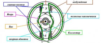
What is the process of operation of an electric motor based on?
When a rectangular frame is placed between two poles of magnets, rotating around its axis, and then voltage is applied through it, the frame will begin to rotate. This pattern is used in the operation of mechanisms. The very moment of connecting energy to this frame is very important. If it is rotating, then a special sliding contact is used. When the frame is rotated one hundred and eighty degrees, the energy will flow back through it. It turns out that the movement and its direction will be at the same level. And no smooth rotation. Otherwise you will have to use dozens of frames.
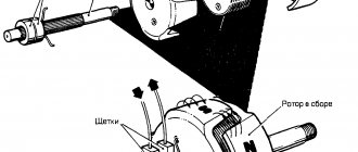
Design of commutator motors:
- tachogenerators - devices that monitor rotational characteristics (if the uniformity of movement is disturbed, they will adjust the voltage supplied to the motor and the movement will become smoother);
- graphite brushes - are the main part of the sliding contact, through which voltage will be supplied to the rotating armatures;
- stators are external magnets, rotors are rotating parts.
Stators sometimes contain not one magnet, but several. Sometimes electromagnetic coils are used instead of a static magnet. Such units operate on both constant and alternating electricity. Rotary axes are directly connected to rotating tools without the use of intermediate mechanisms.
What scheme were the commutator motors connected to?
Variable motors are quite widely used as power units in household appliances, hand-held power tools, electrical equipment of machines and automation systems. The most popular units of this kind are electric motors with low power and high rotational frequency.
How to explain the scope of use of such technology:
- easy controls;
- compactness;
- low cost;
- light weight.
Both single-phase and three-phase motors are capable of operating on both constant and intermittent power. That's why they got the name universal.
Design features
If you delve into the essence of collector equipment, they are quite specific devices that have all the necessary advantages. Machines based on constant electricity, which have similar characteristics, differ from all others in the motor stator housing in order to reduce losses at eddy speeds. They are made of special electrical steel.
Operating principle, commutator motor diagram
What is included in the design of intermittent electricity motors:
- tachogenerators;
- brush-collector mechanisms;
- stators;
- rotors.
The rotors in the motors rotate after the armature power force and the magnetic flux of the winding interact with each other. Through the brush, electricity will be supplied to the collectors, which are assembled from plates with a trapezoidal cross-section. Thanks to the series connection of the field windings, a much larger maximum torque is obtained, but at the same time much higher idle speeds will appear, which will lead to the mechanism failing prematurely.
How to control the operation of the motor
In fact, they use engines that have different ways of regulating their work. The motors are controlled using electronic circuits, in which triacs act as regulating elements, transmitting a given energy to the engine. Triacs act as fast-acting switches, and a control impulse arrives at their gates - it is this impulse that will open it at a certain moment.
In the circuit where a triac is used, the operating principle is implemented, which is based on full-wave phase regulation, when the energy supplied to the motor is tied to a pulse that is supplied to the control electrodes. The rotation frequency of the armatures will be directly proportional to the energy applied to the winding.
What is the voltage control scheme?
- a signal will be transmitted via an electronic circuit to the gate of the triac;
- it will open and electricity will flow along the stator winding, which will give movement to the motor armature;
- the tachogenerator will convert the instantaneous value of the rotation speed into an electrical signal, resulting in feedback being generated;
- as a result, the rotors will rotate evenly under any load;
- the last step is to reverse the electric motor.
Typical malfunctions include brush-collector mechanisms - a spark can be observed in them even while the motor is running. When the brushes fail, they are replaced to prevent more serious damage.
Advantages:
- compactness;
- speed reaction;
- independent existence from the network frequency;
- higher starting torque;
- the presence of soft speed control over a wide range by adjusting the voltage in the network.
The disadvantages of these motors include the need to use brush-collector junctions, and they cause increased noise, the presence of a spark, a short service life, and too many elements in the commutator.