Accurate knowledge of the polarity of an electrical appliance is extremely important. After all, if you connect electrical equipment with incorrect polarity, it may either not work or be completely damaged. In most cases, the “plus” and “minus” of wires and contacts in such devices are indicated by letters, symbols or colors (on the case near the contacts there is a “+” and “-” marker, and the wires are black for minus and red for plus) .
But sometimes it happens that it is not possible to visually determine the poles. To do this, you can use either an ordinary polarity tester or improvised means.
How to determine polarity without instruments
How to determine the polarity of an unknown power source? Let's assume that you come across some kind of constant voltage power supply, battery or accumulator. But... it doesn’t indicate where the plus is and where the minus is. Yes, the matter can be quickly resolved with a multimeter, but what if you don’t have one at hand? Calmly. There are three proven working methods.
Using water
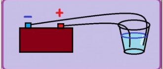
I think this is the easiest way to determine polarity. First of all, pour some water into a container. Preferably not metal. We remove two wires from a power source with unknown terminals, drop them into our water and look carefully at the contacts. Hydrogen bubbles will begin to form at the negative terminal. Electrolysis of water begins.
Using raw potatoes
Take a raw potato and cut it in half.
We plug our two wires from an unknown DC source into it and wait 5-10 minutes.
A light green color appears on the potato near the positive terminal.
Using a PC fan
We take a fan from the computer. It has two terminals, and sometimes even three. The third may be the yellow wire - the speed sensor. But we still won’t use it. We only care about two wires - red and black. If there is a plus on the red wire and a minus on the black wire, then the fan will rotate
If you didn’t guess right, then the blades will stand still.
We use a fan if it is known that the power source voltage is from 3 to 20 Volts. Applying a voltage of more than 20 volts to the fan is fraught with death.
Conclusion
In conclusion, I would like to say that these chips cannot be rolled with alternating current. And as you know, single-phase alternating current consists of two wires - phase and zero. For those who don’t remember how they can be determined, please look here. I would also like to wish you never to confuse the polarity, because “foolproof protection” (reverse polarity protection) is not installed in all electronic devices.
The story of the power supply and the gas water heater
One day, while I was repairing the remote control for a client, he told me that he wanted to adapt a power supply to his gas water heater, the one that is powered by two LR20 batteries, so as not to buy rather expensive alkaline batteries. He found a universal power supply that can set the voltage to 3 Volts and is capable of delivering current at a load of up to 1 Ampere.
This current would have been more than enough for the task at hand, but nevertheless the geyser from the power supply did not want to work, while it worked fine from batteries. So what's the deal? But the fact was that a stabilized power supply was needed for the gas water heater.
A little later I will explain the difference between a stabilized and non-stabilized power supply and why some devices work perfectly from an unstabilized source, while others do not.
The incident with this man was the reason to write a short article about how to choose the right power supply for your devices, or as it is also called a power adapter.
Devices that require an adapter can be not only smartphones, phones or tablets. We are talking rather about devices such as routers, chargers for radiotelephones, digital, satellite set-top boxes and TVs powered by an external power supply, various toys, LED lamps, blood pressure monitors and much more. In general, everything that is powered from the network through a special adapter.
Determining polarity with a multimeter
Sometimes it happens that a new electrical device that needs to be connected does not have polarity markings or it is necessary to re-solder the wiring of a damaged device, and all the wires are the same color
In such a situation, it is important to correctly identify the poles of the wires or contacts. But if you have the necessary instruments, a logical question arises: how to determine the plus and minus of an electrical appliance with a multimeter?
To determine the polarity, the multimeter must be turned on in the mode for measuring direct voltage up to 20 V. The wire of the black probe is connected to the socket marked COM (it corresponds to the negative pole), and the red one is connected to the socket with the VΩmA marker (it is, accordingly, a plus).
After this, the probes are connected to the wires or contacts and the device, the polarity of which needs to be determined, turns on. If the multimeter display shows a value without additional signs, then the poles are determined correctly, the contact to which the red probe is connected is positive, and the contact to which the black probe is connected will correspond to the minus. If the multimeter shows a voltage value with a minus sign, this will mean that the probes are connected to the device incorrectly and the red probe will be a minus, and the black probe will be a plus.
If the multimeter used to measure is analog (with an arrow and a display with gradations of values), if the poles are connected correctly, the arrow will show the actual voltage value, but if the poles are reversed, then the arrow will deviate in the opposite direction relative to zero, that is, it shows a negative current value.
Details about the polarities of LED lamps
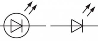
Such small lighting points work on the principle that current flows through them only in the forward direction. This produces optical radiation from the light bulb. If the polarity is not observed when connecting, the current will not be able to make its way through the circuit. Accordingly, the lighting device will not work.
Thus, before installing the LED, the master must know the location of its cathode and anode (“+” and “-”). This is not difficult to do if you know certain principles for visually assessing a light bulb or the operation of electrical appliances in combination with an LED element.
Determine visually
The first way is visual. Let's say you need to determine the polarity of a brand new LED with two leads. Look at its legs, that is, its conclusions. One of them will be shorter than the other. This is the cathode.
You can remember that this is a cathode by the word “short”, since both words begin with the letters “k”. The plus will correspond to the pin that is longer. Sometimes, however, it is difficult to determine the polarity by eye, especially when the legs are bent or have changed their sizes as a result of the previous installation.
Looking into the transparent case, you can see the crystal itself. It is located as if in a small cup on a stand. The output of this stand will be the cathode. On the cathode side you can also see a small notch, like a cut.
But these features are not always noticeable in LEDs, since some manufacturers deviate from the standards. In addition, there are many models made according to a different principle. Today, on complex structures, the manufacturer puts “+” and “−” signs, marking the cathode with a dot or a green line, so that everything is extremely clear. But if there are no such marks for some reason, then electrical testing comes to the rescue.
Methods for detecting polarity
There are several basic methods by which you can find out where the plus of the LED is and where the minus is. The easiest way is to visually inspect the element and determine the polarities by appearance.
A characteristic feature of new LED elements is the length of the legs. The anode (plus) will always be longer than the cathode (minus). As a reminder to the master, the first letter “K” from the word “cathode” means “short”. You can also visually evaluate the bulb bulb. If it is clearly visible, the master will see the so-called “cup”. It contains a crystal. This is the cathode.
It’s also worth paying attention to the rim of the LED part. Many manufacturers prefer to place a special designation marking opposite the cathode. It may look like a notch, a small slice or a dot. It's hard not to see them.
A new version of LED marking is the “+” and “-” icons on the base. In this way, the manufacturer makes it easier for the technician to work and helps determine polarities. Sometimes it is possible to mark with a green line opposite the plus.
Using a Multimeter
If it is not possible to determine the LED - anode / cathode - visually, you can use special equipment. This is what a multimeter is. The entire verification procedure will take no more than a minute. They act this way:
- The device is set to resistance measurement mode.
- The multimeter probes are carefully connected to the legs of the LED light bulb. The supposed plus is placed on the red wire. Minus - to black. In this case, the touch is made short-lived.
- If the contacts are installed correctly, the device will show a resistance close to 1.7 kOhm. If the connection is incorrect, nothing will happen.
Color of wires plus (+) and minus (-) in DC networks
Is the red wire positive or negative? Such questions arise when working with DC electrical circuits.
Red
To remember which plus is red or black, they use the name of a well-known international organization - the Red Cross. This phrase suggests that red means plus.
Black
Black color indicates the negative conductor. These markings can be seen on typical household equipment:
- power supplies;
- audio, video equipment;
- other devices with electronic software control units.
Plus
The polarity of conductors must be observed when repairing standard electrical equipment of cars. In some situations, confusion with plus and minus is accompanied by a violation of the functional state.
Minus
The high power of connected consumers increases the responsibility for performing repair and adjustment work. In such situations, it is necessary to eliminate errors in determining polarity. Strong direct current is used to supply electricity:
- warehouse and municipal transport;
- lifting mechanisms;
- sensors and automation.
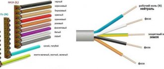
Marking of wires for alternating three-phase current
The special color designation of the shell helps to determine the purpose of individual lines even without studying the accompanying design documentation:
- gray, purple, orange or red wire – phase;
- yellow and green stripes – grounding;
- blue or a combination of white and blue stripes is neutral.
Such designations simplify installation operations when laying power lines, during the assembly of electrical panels
It is especially important to eliminate errors when hidden installation of communications inside building structures is used. In this case, correcting incorrect actions will be accompanied by increased costs
ATX
This term has other meanings, see ATX (meanings).
ATX
(from the English Advanced Technology Extended) - the form factor of personal desktop computers. It has been the dominant standard for mass-produced computer systems since 2001.
The ATX standard defines the following characteristics:
- geometric dimensions of motherboards;
- general requirements for the position of connectors and holes on the housing;
- the shape and position of a number of connectors (mainly power);
- geometric dimensions of the power supply;
- position of the power supply mounts in the case;
- electrical characteristics of the power supply;
Story
Developed and offered to computer system manufacturers in 1995 by Intel to replace AT, which had been used for a long time. In addition to Intel itself, replacement began to be made by OEM equipment suppliers (HP, etc.
), then was picked up by suppliers of components - motherboards and power supplies for them. Massive displacement of the previous standard occurred at the end of 1999 - beginning of 2001.
Other modern standards (microATX, flexATX, mini-ITX) usually retain the main features of ATX, changing only the size of the board and the number of expansion slots.
During its existence, the ATX specification has undergone a number of changes, expressed in standards:
- ATX 1.0 Standard;
- ATX 1.1 Standard;
- ATX 1.2 Standard;
- ATX 1.3 Standard;
- ATX 2.0 Standard;
- ATX 2.01 Standard;
- ATX 2.1 Standard;
- ATX 2.2 Standard;
- ATX 2.3 Standard;
- ATX 2.31 Standard;
- ATX 2.32 Standard;
- ATX 2.4 Standard;
In 2003, Intel announced a new standard - BTX, in particular aimed at increasing the cooling efficiency of the computer system unit.
The company's main calculation for replacing ATX was related to the ever-increasing thermal power dissipated by computer components, primarily processors.
The format change that had begun soon stopped - most of the computer industry abandoned the mass distribution of the new format due to a steady trend towards a decrease in the power dissipated by computer components.
As of 2022, ATX
and its derivatives remain the most widespread and there are no plans to replace it in the near future.
Main differences between ATX and AT
Main article: AT (form factor)
- The processor's power is controlled by the motherboard. To ensure the operation of the control unit and some peripheral devices, even when turned off, a standby voltage of 5 and 3.3 Volts is supplied to the board. Although many instructions strongly suggest unplugging the power cord to safely replace components, many ATX power supplies have a disconnect switch on the case.
- The fan on the rear wall of the power supply can be supplemented (or replaced) by a 12-14 cm fan installed on the bottom of the power supply, which allows you to create more air flow at lower speeds and, accordingly, less noise. The arrangement of elements on the motherboard is oriented in such a way that the processor heatsink is in the path of the air flow from the power supply fan. Currently, there is a tendency to separate air flows: the power supply is placed at the bottom of the case, the air flow to it comes either from under the case, or (less often) from the inside, from the video card. In the original ATX specification, the power supply fan located at the bottom was a supply fan relative to the case and was intended to blow air through the CPU heatsink.
- The power connector has changed: in order to avoid the mistaken connection of two similar power connectors in the previous standard, in the ATX standard the connector with a key has an unambiguous inclusion. Due to the increase in power consumed by the computer, the number of pins in the ATX power connector increased first to 20, then to 24; At the same time, additional connectors appeared: first 4- and then 8-pin, connecting 12 V via a separate power line.
- The rear panel has changed: in the AT standard there was only a hole for the keyboard connector on the rear panel, boards installed in expansion slots and “brackets” with connectors connected to the motherboard via flexible cables were installed in slots; In the ATX
, the keyboard (and mouse) connectors are traditionally on the top, the rest of the space on the back panel is occupied by a rectangular hole of a fixed size, which the motherboard manufacturer can fill with connectors in any order. Included with the motherboard is an “IO plate” with slots for the connectors of a specific motherboard (this allows you to use the same case for motherboards with completely different sets of connectors). Additional functions of the “plug” are the reduction of emitted EMR and the formation of a single chassis ground loop.
Determining polarity with a multimeter
Sometimes it happens that a new electrical device that needs to be connected does not have polarity markings or it is necessary to re-solder the wiring of a damaged device, and all the wires are the same color
In such a situation, it is important to correctly determine the poles of the wires or contacts
But if you have the necessary instruments, a logical question arises: how to determine the plus and minus of an electrical appliance with a multimeter?
To determine the polarity, the multimeter must be turned on in the mode for measuring direct voltage up to 20 V. The wire of the black probe is connected to the socket marked COM (it corresponds to the negative pole), and the red one is connected to the socket with the VΩmA marker (it is, accordingly, a plus).
After this, the probes are connected to the wires or contacts and the device, the polarity of which needs to be determined, turns on.
If the multimeter display shows a value without additional signs, then the poles are determined correctly, the contact to which the red probe is connected is positive, and the contact to which the black probe is connected will correspond to the minus.
If the multimeter shows a voltage value with a minus sign, this will mean that the probes are connected to the device incorrectly and the red probe will be a minus, and the black probe will be a plus.
If the multimeter used to measure is analog (with an arrow and a display with gradations of values), if the poles are connected correctly, the arrow will show the actual voltage value, but if the poles are reversed, then the arrow will deviate in the opposite direction relative to zero, that is, it shows a negative current value.
Determination of polarity by alternative methods
If it happens that you don’t have a multimeter at hand, but you need to find the polarity, you can use alternative and “folk” means.
For example, speaker wiring charges are checked using a 3-volt battery. To do this, you need to briefly touch the wires connected to the battery to the speaker terminals.
If the cone in the speaker begins to move outward, this will mean that the positive terminal of the speaker is connected to the positive terminal of the battery, and the negative terminal to the negative terminal. If the diffuser moves inward, the polarity is reversed: the positive terminal is connected to the minus, and the negative terminal to the plus.
If you need to connect a DC power supply or battery, but there are no polarity markings on them, and you don’t have a multimeter at hand, plus and minus can be determined by “folk” methods using improvised materials.
The easiest way to determine polarity that you can use at home is to use potatoes. To do this, you need to take one raw potato tuber and cut it in half. After this, two wires (preferably of different colors or with any other distinctive sign) with their bare ends are stuck into a cut of potato at a distance of 1-2 centimeters from each other.
The other ends of the wires are connected to the constant current source being tested, and the device is turned on (if it is a battery, then after connecting the wires, nothing else needs to be done) for 15-20 minutes. After this time, a light green spot will form on the potato cut around one of the wires, which will be a sign of a positive charge on the wire.
The second method also does not require any special devices or tools. To determine the polarity of the wires of a DC source, you will need a container of warm water into which two wires connected to the power source are lowered.
Letter designation of wires
Color markings can be supplemented by letters. Partially the symbols for the designation are standardized:
- L (from the word Line) – phase wire;
- N (from the word Neutral) – neutral wire;
- PE (from the combination Protective Earthing) - grounding;
- “+” – positive pole;
- “-” – negative pole;
- M – midpoint in DC circuits with bipolar power supply.
To designate the protective grounding connection terminals, a special symbol is used, which is stamped on the terminal or on the device body in the form of a sticker. The grounding symbol is the same for most countries in the world, which reduces the likelihood of confusion.
In multiphase networks, the symbols are supplemented by the serial number of the phase:
- L1 – first phase;
- L2 – second phase;
- L3 – third phase.
There is marking according to old standards, when the phases are designated by the symbols A, B and C.
A deviation from the standards is the combined phase designation system:
- La – first phase;
- Lb – second phase;
- Lc – third phase.
In complex devices, additional symbols may be found that characterize the name or number of the circuit
It is important that the markings of the conductors match throughout the entire circuit where they are involved
Letter designations are applied with indelible, clearly visible paint on the insulation near the ends of the cores, on sections of PVC insulation or heat-shrinkable tube.
Connection terminals may have marks that indicate circuits and power polarities. Such signs are made by painting, stamping or etching, depending on the material used.
But what if there is no old adapter?
Then we pay attention to the body of the device itself for which we want to purchase a power adapter. Next to the socket for connecting the adapter, a manufacturer that respects itself and its customers will also indicate the necessary parameters in the form of symbols already familiar to you, indicating the required voltage, current, and polarity. Sometimes these parameters are indicated in the instructions or written on a special label glued to the device body.
If none of this is available, then proceed as follows:
- Find out the required voltage - to do this, you need to count how many batteries are inserted into the device and calculate their total voltage. The voltage of one battery is usually 1.5 volts with the exception of some types. Check with the batteries you are using.
- We find out the required current - of course it can be measured, but there is no particular need for this. In battery-powered devices, an adapter capable of delivering a current of 1000 mA (1 A) or even less will be sufficient.
- Polarity - it is advisable to verify the wiring method, but as already written, more often than not, in about 90% of cases this wiring is used - “plus” inside “minus” outside.
- The connector is selected by “trying on”.
Yellow-green grounding
The grounding conductor, or earth, serves for safety. The name comes from the fact that through this connection a dangerous charge (for example, formed on the body of a faulty device) instantly flows into the ground. Thus, grounding protects a person from electric shock.
There may not be a grounding wire in single-phase networks of old buildings, but this is becoming less and less common - during repairs, electricians recommend and install a network with ground.
Most often, the insulation of the ground wire is yellow-green. Sometimes the wire is only yellow or white with a green stripe. Grounding is marked with the letters “PE” - from the English “protective earthing” (protective grounding). But on diagrams, housings and terminal blocks it may be indicated not by letters, but by special symbols (see table).
ADVICE:
There is no complete guarantee that the wires in your home are connected in accordance with the colors - the human factor occurs in any area. In addition, the insulation of the wires may be the same color. In this case, you can also handle it yourself - an indicator screwdriver will help. This is a very simple tool that can be purchased at almost any hardware store.
The transparent handle of this screwdriver has a neon light or LED. At the end of the handle there is a contact plate on which you need to keep your finger during testing. If you touch the exposed wire of a live phase with a metal tip (probe) of a screwdriver, the light bulb will light up, but if there is no zero wire, it will not.
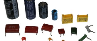
Capacitor Characteristics
The main characteristic of any capacitor is its capacity, which determines the amount of accumulated charge. The capacitance depends on the area of the plates and the thickness of the dielectric layer.
Attention! The area of the plates cannot be increased indefinitely, as this leads to an increase in the dimensions and weight of the device. The thickness of the dielectric layer can also be reduced only to a certain value, since any insulator has its own electrical strength limit
In this regard, the second main characteristic is the operating voltage at which the capacitor retains its properties throughout its entire service life
The thickness of the dielectric layer can also be reduced only to a certain value, since any insulator has its own electrical strength limit. In this regard, the second main characteristic is the operating voltage at which the capacitor retains its properties throughout its entire service life.
Exceeding the operating voltage leads to electrical breakdown and malfunction of the device, in particular, in some applications it is necessary to take into account additional parameters, namely:
- Temperature coefficient, which takes into account the effect of heating on the capacity of the radio element;
- Dielectric loss tangent, characterizing the properties of a radio element when operating at high frequencies;
- Switching polarity, which arises due to the design features of certain types of devices.
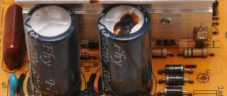
To increase the capacity while maintaining acceptable dimensions, it is necessary to apply various technical subtleties. For example, in electrolytic capacitors, a narrow and long strip of aluminum foil is used as one of the plates. A thin layer of oxide on the surface of the foil acts as an insulator, and a liquid electrolyte is used instead of a second plate. To make such a capacitor, a sheet of foil is rolled into a thin cylinder, which is then placed in the housing.
Electrolytic capacitor
This design combines a large plate area and a small dielectric thickness, which makes it possible to obtain very large capacitance values with small dimensions.
The main disadvantage of such capacitors is the need to strictly observe the polarity of the connection. Failure to comply with this requirement leads to high currents, leaks and structural failure. Electrolytic capacitors must have polarity markings for proper connection.
Color of wires plus ( ) and minus (-) in DC networks
Is the red wire positive or negative? Such questions arise when working with DC electrical circuits.
Red
To remember which plus is red or black, they use the name of a well-known international organization - the Red Cross. This phrase suggests that red means plus.
Black
Black color indicates the negative conductor. These markings can be seen on typical household equipment:
- power supplies;
- audio, video equipment;
- other devices with electronic software control units.
The polarity of conductors must be observed when repairing standard electrical equipment of cars. In some situations, confusion with plus and minus is accompanied by a violation of the functional state.
The high power of connected consumers increases the responsibility for performing repair and adjustment work. In such situations, it is necessary to eliminate errors in determining polarity. Strong direct current is used to supply electricity:
- warehouse and municipal transport;
- lifting mechanisms;
- sensors and automation.
Something to remember! Domestic standards have changed several times over the past decades. Currently, the markings discussed above are used.
https://www.youtube.com/watch?v=channelUChB8KhWMvtTMXpi-zgHx5FQ
The color options for the shells will help you recognize the intended purpose of the conductors:
- blue – working zero;
- transverse or longitudinal combinations of yellow and green stripes - protective zero;
- main blue with a change to a combination of yellow and green stripes at the junctions - combined working and protective zero.
For your information. The last universal option can be done in the reverse way. The main part of the line is created from a combination of yellow and green stripes, with blue color applied at the junctions.
Checking polarity
AC current can be tested using a multimeter or ohm voltmeter. Testing with a multimeter usually involves touching the positive and negative leads from the meter to the wiring being tested.
Voltmeter
Note! A flashing negative sign ("-") before the digital readout on the meter indicates incorrect polarity
Reverse polarity
If one of the outlets in your home is found to have reverse polarity, it is not difficult to correct the problem, but you will need to be careful to avoid electrocution. Before inspecting the wiring, you must turn off the household power supply. The positive wires, which are usually red or black, should be connected to a brass terminal. The neutral wires, which are usually white or gray, should be connected to a light-colored chrome terminal.
Important! If the wires are connected incorrectly, the polarity will be reversed, causing the current to flow in the opposite direction. This could result in electric shock to anyone who touches the device or outlet, and even damage to the device itself.
What is battery polarity?
The current carrying elements of the battery are located on its front or top cover. There are two main layouts of current leads - “direct” and “reverse”; to put it simply, the whole difference is in the location of the terminals - the positive terminal can be on the right or left, which is the main difference between batteries with direct and reverse polarity.
1. Features of straight polarity of a car battery
Straight polarity is found only on domestically produced cars and is usually marked as “1”. To determine the polarity, turn the battery so that the front part of the battery is facing you so that the current carrying elements are at the bottom and the label is in front of your eyes. If the battery polarity is straight, the positive terminal will be on the left and the negative terminal on the right.
2. Features of reverse polarity of a car battery
With rare exceptions, reverse polarity batteries are found on European cars.
The differences between reverse and direct polarity batteries are minimal, externally they are almost identical (case, current strength, number of cans, label), which is why you can easily confuse and buy a battery with the wrong position of the current leads. That is why, if you are thinking about replacing the battery, you need to know exactly which battery is suitable for your car.
How to determine ground, zero and phase on wires if there are no markings
It is more difficult to determine in practice than in theory. Not all manufacturers comply with the standards. Therefore, when laying a two-phase 220 V network with grounding, you have to use a VVG cable with blue, brown and red colors. Combinations may be different, but without complying with regulatory requirements.
For your information. In old wiring from “Soviet times” there is no color marking. Identical white (gray) shells do not allow the purpose and correspondence of the lines to be known by simple visual inspection.
To avoid problems, it is recommended to carry out installation work using the same type of cable products. When color coding is not available, it should be created at the joints using insulating tape or heat shrink tubing. The latter option is preferable, as it is designed to maintain integrity for a long time.
Below are methods for determining phase and neutral wires with the advantages and disadvantages of each option. In any case, first clarify the network parameters. In old houses, for example, a two-wire connection scheme with a single working and grounding conductor is often used.
The figure shows a modern network with separate grounding and working zero connections. It is possible to connect three- and single-phase loads.
Determining the phase using an indicator screwdriver
Touching the tip of such a device to the phase wire closes the current circuit. This is accompanied by the warning lamp or LED lighting up. A built-in resistor limits the current to a safe level.
Advantages of the indicator:
- minimum cost;
- compactness;
- reliability;
- durability;
- autonomy;
- good protection from adverse external influences.
The disadvantage is the limited measurement accuracy. Under certain conditions, false positives cannot be ruled out.
Determination of ground, zero and phase using a test lamp
To reproduce this technology, you need to prepare a simple design. An incandescent lamp designed for the appropriate mains voltage is screwed into a standard socket. Connect wires of sufficient length to perform work operations in a specific location.
Next, connect one of the wires to the known zero line. Others sequentially check other cable cores. Lighting of the lamp indicates the presence of a phase.
Using a measuring device
When checking a 220 V household network, you do not need to know how to determine the polarity. The power supply is organized using alternating current, so set the multimeter switch to the appropriate position. Touching the phase-zero (phase-ground) wires with the probes is accompanied by an indication of the corresponding voltage (≈220 V). The potential difference between the neutral conductor and ground is minimal.
For your information. When checking an old two-wire circuit, one of the probes touches the reinforcement in a concrete slab, a radiator of a heating system, or another grounded element of a building structure.
When switching to constant voltage, the multimeter will show where the plus and minus are. In the absence of reliable information about the electrical parameters in the circuit, they begin with the maximum measurement range with a sequential transition to smaller values with insufficient accuracy.
Such a “device” is useful for testing DC circuits in the absence of specialized measuring instruments. Bubbles near the negative wire are the release of hydrogen during the electrolysis reaction. The area near the plus will take on a greenish tint after a few minutes.
Using LED
You can create a control device with your own hands by analogy with an indicator screwdriver. Instead of a light bulb, install AL 307 or another LED with similar characteristics. A 100-120 kOhm resistor with a power of 1-2 W is added in series to the circuit.
Colors for 220V and 380V networks
Installation of single- and three-phase electrical networks is facilitated if the wiring is made with multi-color wire. Previously, a flat two-core white wire was used for single-phase residential wiring. During installation and repair, to eliminate errors, it was necessary to ring each core individually.
The production of cable products with colored cores in different colors reduces the labor intensity of the work. To indicate phase and zero in single-phase wiring, it is customary to use the following colors:
- red, brown or black – phase wire;
- other colors (preferably blue) – neutral wire.
The phase markings in a three-phase network are slightly different:
- red (brown) – 1 phase;
- black – 2 phase;
- gray (white) – 3 phase;
- blue (cyan) – working zero (neutral)
- yellow-green – grounding.
Domestic cable products comply with the standard for core coloring, so a multiphase cable contains differently colored cores, where the phase is white, red and black, the neutral is blue, and the ground is yellow-green conductors.
When servicing networks installed according to modern standards, it is possible to accurately determine the purpose of the wires in the junction boxes. If there is a bundle of multi-colored wires, the brown one will definitely be phase. The neutral wire in distribution boxes has no branches or breaks. The exception is branches to multi-pole switching devices with complete circuit breaking.
ᐉ Buy connectors of all types at the best price in Kyiv with delivery throughout Ukraine
Showing 33 of 815 products
- Connector type: plug Plastic case
- Screw-on
- Connector: 3 pin
- Mounting method: On cable Plug diameter: 6.3mm Type of execution: straight Mono/stereo: stereo Overall connector length: 30.3mm Pin length: 20mm
- Connector: micro USB 5 pin Type: plug Type of execution: straight
- Connector: USB A Type: female Type of execution: straight
Type: plug Connector: RCA Mounting method: under cord Housing material: plastic Color: yellow
Type: plug Connector: RCA Mounting method: under cord Housing material: plastic Color: white
Type: plug Connector: RCA Mounting method: under cord Housing material: plastic Color: red
Type: plug Connector: RCA Mounting method: under cord Housing material: plastic Color: green
Type: plug Connector: RCA Mounting method: under cord Housing material: plastic Color: blue
Connector: PowerCon Number of contacts: 3 Type: wire Housing: plastic
Connector: PowerCon Number of contacts: 3 Type: wire Housing: plastic, moisture-resistant
What color are the poles in the wires?
The protective neutral cable connects the protective ground and N-neutral cables. These types require double grounding along the line. The marking of electrical wires is the same as for the protective conductor, yellow-green. Blue color was also used in older installations, but nowadays such markings are rare. It is much more common to see installations marked with alternative yellow and green stripes.
Note! The very tip of the protective neutral cable is usually marked blue. Neutral cable is found in very old electrical installations
It was used in cases where circuits did not yet have neutral and protective cables. The installation only had phase and ground neutral wires, which could be identified by their blue color. Today the neutral conductor is no longer used in electrical installations
The neutral cable is found in very old electrical installations. It was used in cases where circuits did not yet have neutral and protective cables. The installation only had phase and ground neutral wires, which could be identified by their blue color. Today, the neutral conductor is no longer used in electrical installations.
Green cable with positive potential
Green color is for electrical cables with positive potential.
In electronic devices, positive charge flows in the red wires, negative charge in the black wires.
Description of poles
In the case of an electric current passing between two points, or poles, one of the poles will have more electrons than the other. The pole with more electrons is said to have a negative charge. The pole with fewer electrons has a positive charge. When two poles are connected by a wire, electrons move from the negative pole to the positive pole. This flow is called electric current.
Polarity can be of different types
For your information! In a DC circuit, one pole is always negative and the other positive with electrons flowing in only one direction. In an alternating current (AC) circuit, the two poles alternate between negative and positive poles with the electrons flowing in the opposite direction.
Ground wire color
By modern standards, the ground conductor is yellow-green. It usually looks like yellow insulation with one or two longitudinal bright green stripes. But there are also transverse yellow-green stripes in color.
Grounding may be this color
In some cases, the cable may only have yellow or bright green conductors. In this case, the “earth” has exactly this color. It is displayed in the same colors on diagrams - most often bright green, but it can also be yellow. Signed on circuit diagrams or on ground equipment in Latin (English) letters PE. The contacts to which the “ground” wire must be connected are also marked.
Sometimes professionals call the grounding wire “neutral protective”, but do not be confused. This is an earthen one, and it is protective because it reduces the risk of electric shock.
Other types of polarity markings
There are generally accepted standards for indicating polarity; they are mandatory not only for alternating current circuits, but also for alternating voltage – single- and three-phase. The standards are:
- red or brown. This insulation is typical for phase wires;
- blue or black. Means "ground" or, more simply, zero;
- color combination. Used to designate grounding conductors. Yellow and green alternate.
The above colors are basic. However, in practice there are other shades, which sometimes confuses users.
Wire marking
Wire marking is the application of a specific mark to their outer surface to indicate the required characteristics. Marking can be in the form of color markings, inscriptions (numbers and letters), labels or tags.
Important! Letter or numerical markings indicate the material of the shell and cores, cross-sectional area, number of cores inside and other parameters. The red wire indicates the positive phase or plus
You can remember it by the name “Red Cross”. Black corresponds to negative phase
The red wire indicates the positive phase or plus. You can remember it by the name “Red Cross”. Black corresponds to the negative phase.
But this designation does not always work: the colors may be different, for example, green and blue, or absent altogether. There are many more colors in three-phase wires:
- The phase is indicated by red, orange, purple or gray colors:
- Neutral - blue or white-blue;
- Grounding - stripes of green or yellow colors.
To avoid mistakes during installation, if in doubt, it is better to check the polarity in advance.
Wire Classification Options
The typical cable name contains letters and numbers. By decoding these symbols you can find out the main characteristics of products in this category:
- conductor (shell) materials;
- number of cores;
- cross-sectional area;
- Extra options.
Standard designation according to GOST
Example of decoding (AVBbv-ng):
- A – the core is made of aluminum (copper is not marked);
- B – insulating shells are made of PVC;
- BB – protection against mechanical damage, made of steel tape without a damping gasket;
- ng – components that prevent combustion have been added to the polymer shell.