The author of the article is a professional tutor, author of textbooks for preparing for the Unified State Exam Igor Vyacheslavovich Yakovlev
Topics of the Unified State Examination codifier: carriers of free electric charges in metals.
In this worksheet, we begin a detailed study of how electric current flows in various conducting media - solids, liquids and gases.
Let us recall that a necessary condition for the occurrence of a current is the presence in the medium of a sufficiently large number of free charges that can begin to move in an orderly manner under the influence of an electric field. Such media are precisely called conductors of electric current.
Metal conductors are the most widely used. Therefore, we begin with questions of the propagation of electric current in metals.
We have talked many times about free electrons, which are carriers of free charges in metals. You are well aware that electric current in a metal conductor is formed as a result of the directed movement of free electrons.
What are conductors and non-conductors?
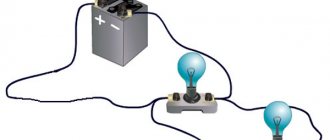
Substances through which electrical charges are transmitted are called conductors of electricity. Good conductors of electricity are metals, soil, solutions of salts, acids or alkalis in water, graphite. Substances through which charges are not transferred are called non-conductors (or insulators). ...
Interesting materials:
Is it possible to enter the theater with an electronic ticket? Is it possible to bake a non-stick frying pan? Is it possible to consult with MFC? Is it possible to rinse your nose if you have sinusitis? Is it possible to view a presentation without Power Point? Is it possible to just lay linoleum? Is it possible for a baby to have millet porridge? Is it possible to pay with a torn banknote? Is it possible to overclock an i5-2400 processor? Is it possible to heat food in a plastic container in the microwave?
Electricity. Charge carriers
Electric current is the directional movement of electric charges. If a substance contains free charge carriers - electrons, ions, capable of moving over significant distances, then when an electric field is applied, they acquire directional movement, which is superimposed on their thermal chaotic movement. As a result, free charge carriers drift in a certain direction. Speaking of electric current as the directed movement of free charge carriers, we abstract from chaotic motion, since it does not contribute to the formation of electric current.
The main characteristic of current is the current strength, numerically equal to the charge flowing through the cross section of the conductor per unit time. If the current I is constant, then I = q/t,
and in the general case I = .
The unit of current is ampere (A):
A current that does not change over time is called constant.
Both positive and negative carriers can participate in the formation of current; the electric field moves them in opposite directions. The direction of the current is usually determined by the direction of movement of the positive carriers. If positive (along the field) and negative (against the field) carriers simultaneously move in an electric field, then the total current is determined as the sum of the currents formed by carriers of each sign.
The current density j is a value equal to the ratio of the current dI flowing through the area dSx, perpendicular to the direction of movement of the carriers, to the area of this area. Unit of current density A/m2. Current density is a vector quantity; it has the direction of the average speed of the ordered movement of positive carriers:
j = qnv+,
where n is the carrier concentration and q is the charge of the carrier. If q < O,
then the vectors and v have opposite directions.
The medium provides a certain resistance to the movement of charges. Therefore, in a homogeneous substance at constant field strength, charges move with a constant average speed v, proportional to the field strength:
v = uE,
where u is the mobility of carriers, equal to the speed of their directional movement under the influence of a field with a strength E = 1 V/m. The mobility of carriers depends on their nature, as well as the density and state of the substance.
When current passes through a substance, electrical energy can be converted into internal, chemical, etc. However, the most common manifestation of electric current under any conditions is the appearance of a magnetic field in the surrounding space.
Ohm's law. Conductor resistance.
The simplest laws of electric current are for metals. For them, the proportionality between the current strength and the potential difference (voltage) U at the ends of the conductor is well satisfied:
This is Ohm's law for a section of a circuit. Here R is the conductor resistance. The unit of resistance is 1 ohm. The reciprocal of resistance is called the conductivity of the conductor.
The graph of current I versus voltage U is called the current-voltage characteristic of a conductor. For a metal at a constant temperature it is linear (Fig. a). For gases, the current-voltage characteristic can have a complex shape (Fig. 61, b); Ohm's law is satisfied in this case only at low current strength (section OA). The current-voltage characteristics of semiconductors and liquids over a wide voltage range are also nonlinear.
This means that their conductivity does not remain constant.
The amount of heat generated by a conductor when an electric current passes through it is equal to the work done by the current and is determined by the Joule-Lenz law:
dQ = I2R dt,
where dQ is the amount of heat in joules.
Resistance of a homogeneous conductor of length l
and cross-sectional area S is expressed by the formula
where r is the resistivity of the substance (the unit of this value is 1 Ohm×m). Magnitude, reverse
The specific resistance is called the specific electrical conductivity of the substance.
Let's find the connection between the vectors of current density and field strength E at some point of the conductor. In the vicinity of this point, let us mentally select a small cylinder oriented along the lines of tension. The voltage along the length of the cylinder is equal to E l
, the current strength through its cross section DS is equal to jDS, and the resistance of the cylinder. Substituting these values into the formula of Ohm's law, we obtain (after abbreviations):
The directions of the vectors j and E coincide. This formula expresses Ohm's law in differential form: the current density is proportional to the electric field strength and has the same direction as it. In this form, Ohm's law expresses the relationship between quantities related to a given point (locally), and is therefore applicable to inhomogeneous conductors.
EMF of the source. Ohm's law for a non-uniform section of a circuit
Let a constant current flow in a closed circuit. If a homogeneous metal conductor is connected to the poles of the current source (Fig. a), then inside this conductor (external section of the circuit) there is an electric field, under the influence of which charges move. For this field to exist at the source poles there must be
be a potential difference, this potential difference determines the presence of an electric field inside the source. If charges in an external circuit move under the influence of an electric field, then inside the source the charges must move against the field forces. This is possible if there are forces of non-electrostatic origin inside the source - external forces. Figure b conventionally shows the distribution of potential along a closed circuit (potential is plotted vertically). Third-party forces can be forces of any nature, except Coulomb forces (in galvanic cells these are chemical forces). A physical quantity equal to the work of external forces when moving a unit charge in a given section of the circuit is called the electromotive force acting in this section (denoted by the letter x):
EMF is the most important energy characteristic of a source, measured, like potential, in volts (V). A section of a chain is called inhomogeneous if, in addition to Coulomb forces, external forces act on it. This is section 1-2 in the figure. The resistance of this section is R12, and the emf is xl2. A potential difference is maintained between points 1 and 2. Since the section under consideration is an integral part of a circuit in which there may be other sources, the direction of the current in this section can be any. Let the current flow from point 1 to point 2. During the time dt, the charge dq = Idt flows. Work of Coulomb and third-party forces on charge transfer
dAK + dAcm = (j1 - j2)dq + x12dq is equal to the amount of heat released in the area
dQ = IR12dq.
Equating the right-hand sides of these two equalities, we get:
The formula expresses Ohm's law for a non-uniform section of the chain. The product IR12 = U12 in equality is called the voltage in the section. The signs of voltage U12, potential difference and EMF can be either positive or negative and are determined relative to the selected direction of bypassing the circuit section.
Literature: T.I. Trofimova Physics course. M. 1990 p. 154-162
Electrodynamics
A magnetic field. Induction and magnetic field strength
Conductors carrying current interact with each other, being located at some distance. These interactions occur through a magnetic field. A magnetic field is a type of matter through which the interaction of moving electric charges occurs. Experiments have shown that a magnetic field accompanies any transfer of charges in the coordinate system under consideration: current in conductors, liquids and gases, the movement of electrons or ions in a vacuum, the movement of a charged body. A magnetic field is not detected around charges at rest in a given coordinate system.
A magnetic field can be detected by its forceful effect on currents, moving charged particles, and magnetized bodies (magnetic needle). To study the magnetic field, you can take a small closed test circuit with current and place it at the points of the field being studied. The magnetic field orients such a free circuit (like a magnetic needle) in a certain way. Experience shows that the maximum value of the moment of force M turning the test circuit is proportional to the area S of the circuit and the current strength I in it:
M~IS.
The value rt = IS is the modulus of the so-called magnetic moment of the current-carrying circuit. The magnetic moment p itself is a vector:
Pm=ISn,
where n is the unit vector normal to the plane of the circuit, associated with the direction of the current in the circuit by the right-hand screw rule.
As shown in the figure, magnetic induction B is a vector whose direction coincides with the direction of the normal to the plane of the test circuit with current in the position of its stable equilibrium
(or with the direction of the north pole N of the magnetic needle). The magnetic induction vector B is the main force characteristic of the magnetic field (similar to the intensity vector E for the electric field). The unit of magnetic induction is tesla (T):
For magnetic fields, the principle of superposition is valid: the magnetic induction of the field B created by several currents is equal to the vector sum of the inductions Bi of the fields of each of the currents separately.
The magnetic field is depicted using magnetic induction lines, which are constructed according to the same rules as electric field lines. Magnetic induction lines are always closed; they have no beginning or end. Such fields are called vortex fields. The nature of the magnetic field induction lines of direct current, a single turn with current, a solenoid and a permanent magnet is shown in the figure.
The two poles of a magnet - north N and south S - always coexist together. No matter how finely crushing a magnet does not lead to the separation of its poles; they only exist in pairs. A solenoid or coil with current, like a permanent magnet, can be assigned magnetic poles and represented as a magnetic dipole, characterized by the vector of the magnetic moment Hg. Any magnetic dipole is a carrier of its own magnetic field.
Induction B (under other identical conditions) depends on the properties of the medium. Induction B in a medium (substance) and induction Bo in vacuum are related by the relation
B = m B0,
The dimensionless quantity m characterizes the magnetic properties of the medium and is called the magnetic permeability of the medium.
Along with induction B, there is another characteristic of the magnetic field - intensity H, associated with magnetic induction B by the relation
where m0 is the magnetic constant.
Vectors B and H in an isotropic medium have the same direction.
The value of H does not depend on the properties of the medium and is determined only by the values and location of the currents that create the magnetic field. The unit of voltage N is 1A/m (ampere per meter).
A uniform magnetic field (B = const) can be obtained inside a long solenoid with current. Its intensity is determined by the current strength I in the solenoid, the number of turns N and length l
solenoid:
H = NI/ l
The flux of the magnetic induction vector (magnetic flux) Ф through an arbitrary area DS in a uniform magnetic field is equal to:
Ф = В × DS × cos a, where a is the angle between the direction of the normal n to the surface DS and the magnetic induction vector B, DS^ is the projection of the DS area onto the plane normal to the induction lines. Magnetic flux Ф is characterized by the number of induction lines penetrating the area. Magnetic flux unit - weber (Wb):
1 Wb = 1 T • m2.
The effect of a magnetic field on a current. Ampere's law. Frame with current in a magnetic field
'- Ampere, based on experiments (1820), established that for a piece of conductor of length A/ with a current / from the side of a uniform magnetic field,
the induction of which is B, the so-called Ampere force acts:
FA = IB l
sina,
where a is the angle between the direction of the current in the conductor and the induction vector B. The formula expresses Ampere's law. The direction of the Ampere force can be found using the left hand rule: if you position your left hand so that the four fingers are directed along the current, and the component of vector B normal to the conductor enters the palm, then the bent thumb will indicate the direction of the force FA. Ampere's force is perpendicular to the plane in which vector B and current I are located, therefore it is always perpendicular to the conductor with current.
For a conductor of complex shape, you can determine the forces acting on individual elements of the current, and then sum them up vectorially and find the resulting force.
Ampere's forces are not central, they do not have a force center. like gravitational or Coulomb forces.
Based on Ampere's law, it is possible to determine the forces acting, for example, on a rectangular frame with current in a uniform magnetic field
with induction B (Fig.). The forces acting on sides ab and cd balance each other. The sides bc and ad are acted upon by forces equal in magnitude:
They form a couple of forces
Taking into account that the area of the frame is equal to S = lr and its magnetic moment pm = IS, we obtain the following expression for the moment of the pair of forces acting on the frame:
M = IBS sin j = рmВ sin j.
At j = 0, the moment M of this pair of forces is equal to zero. Under the influence of a magnetic field, the frame with current is oriented so that the vector of its magnetic moment pm becomes parallel to vector B. This is a stable equilibrium position of the frame, corresponding to the minimum of its energy in the magnetic field. In this position, the Ampere force frame only stretches it.
The orienting effect of a magnetic field on a current-carrying frame underlies the design of many electrical measuring instruments. Let us explain the principle of operation of the magnetoelectric system device.
In devices of this type, a light movable wire frame R, mounted on an axis, is located in the magnetic field of a permanent magnet (Fig. 106). When the measured current passes through the frame, a moment of force arises, which tends to rotate it to an equilibrium position and at the same time twists the spiral spring P. When the torque is balanced by the counteracting moment of the spring, the frame stops and the arrow associated with it gives readings on the scale. As the current increases, equilibrium is achieved at large twist angles and the instrument readings increase. Magnetoelectric instruments (galvanometers, voltmeters, ammeters) are used for measurements in direct current circuits.
Lorentz force
The action of Ampere forces on a current-carrying conductor means that each of the charged particles involved in charge transfer is also acted upon by a certain force Fl from the magnetic field. An expression for this force can be found by taking the ratio of the Ampere force acting on a current-carrying conductor to the number N of charge carriers in it:
Consider a section of a cylindrical conductor of length l
and cross section S, located in a magnetic field (Fig.). If n is the concentration of particles (charge carriers), v is the speed of their directional movement and q is the charge of the particle, then the current density j will be expressed as follows:
j = qvn.
Since I= jS, the formula takes the form:
Fa = qvnSB l
sin a,
Considering that N = nS l
is the number of particles in the volume S
l
of the conductor, we find the force acting on an individual particle:
f = qvB sin
This is the so-called Lorentz force.
The Lorentz force is directed perpendicular to the plane in which
vectors v and B are located. The direction of the Lorentz force fn can be determined by the left-hand rule (for q > 0, four fingers are located along the vector v, for q < 0 - in the opposite direction). The directions of Lorentz forces that act on positive and negative charges are shown in the figure. The Lorentz force acts only on a charge moving relative to the magnetic field (in the coordinate system under consideration).
A characteristic feature of the Lorentz force is that it
being always perpendicular to the velocity vector and, does not do work and does not change the kinetic energy of the free particle. When a charged particle moves in a magnetic field, only the direction of velocity can change, but not its magnitude.
The phenomenon of electromagnetic induction
In 1931, the English physicist M. Faraday, as a result of persistent experimentation, obtained an electric current in a closed wire circuit, influencing it with a magnetic field (in his words, “turned magnetism into electricity”). This phenomenon was called electromagnetic induction, and the resulting current was called induction. This fundamental discovery revealed the inextricable connection between electrical and magnetic phenomena. It served as the basis for the creation of a unified theory of the electromagnetic field and subsequently became one of the foundations of electrical engineering.
From Faraday's experiments it followed that the condition for excitation of the induction current in the circuit is a change in the flux of magnetic induction penetrating the area of this circuit. This change in magnetic flux is achieved in different ways: by changing the module
or the direction of magnetic induction B, the movement of conductors making up the circuit, etc. It was also found that the induced current has a direction in which its magnetic field counteracts changes in the external magnetic flux (Lenz's rule). The induced emf is determined by the rate of change in time of the magnetic flux penetrating the circuit.
The “—” sign in this formula reflects the correspondence of the direction of the induction current to Lenz’s rule. The formula is valid for all possible cases of change in magnetic flux, since the derivation of this formula is based on a universal law of nature - the law of conservation of energy.
Vortex electric field. Eddy currents
The nature of induced emf was revealed by the English physicist Maxwell. He came to the conclusion that any time-varying magnetic field excites an electric field in the surrounding space. This field is the reason for the appearance of induction current in the conductor. The presence of a conductor only helps to reveal this electric field. The essence of electromagnetic induction lies precisely in the excitation of an electric field.
The electric field excited by a non-stationary magnetic field is not associated with charges and has closed lines of tension (unlike the electrostatic field, whose lines of tension are not closed), i.e. it is a vortex field. The vortex electric field does work when moving a charge along a closed path and, therefore, is not potential. This is its fundamental difference from the electrostatic field.
If there is a massive conductor in an alternating magnetic field, then in its thickness, under the influence of an eddy electric field, induction eddy currents (Foucault currents) arise, circulating in planes perpendicular to the magnetic field induction lines. In solid conducting bodies, these currents are very large and lead to strong heating of the bodies. This effect is used to melt metals in induction furnaces. But the appearance of eddy currents in the cores of transformers and electrical machines leads to energy losses. To reduce these losses, the cores are made from insulated plates of sheet electrical steel.
Eddy currents can be excited in electrolytes and ionized gas (plasma). They can also arise in the human body located in an alternating magnetic field. This is used in medicine for deep heating of individual parts of the body for medicinal purposes.
The phenomenon of self-induction. Mutual induction. Transformer
The phenomenon of self-induction consists of exciting an EMF in a circuit when the current flowing through it changes. The magnetic flux associated with the circuit is proportional to the current flowing in it:
Ф = L l
, ‘
where L is a coefficient depending on the shape of the circuit, its dimensions and the magnetic permeability of the medium; it's called inductance
If during the time dt the current in the circuit has changed by dI, then the change in the magnetic flux associated with it is equal to dF = LdI. According to the law of electromagnetic induction, an EMF will appear in the circuit
Inductance L determines the value of the self-inductive emf, which occurs in the circuit when the current in it changes at a speed of 1 A/s. The unit of inductance is henry (H). If the inductance is large, then the current strength in the circuit cannot quickly increase (decrease); As a result, the change in current lags in time from the change in voltage.
Let us calculate the inductance L of a solenoid of length l
, consisting of N turns, each of which limits the area S, and having a core with magnetic permeability m. The magnetic flux penetrating all turns of the solenoid (magnetic coupling) is equal to:
BSN = momHSN.
momHSN = LI.
L = momn2V,
where n is the number of turns per unit length of the solenoid, and V = S l
— solenoid volume.
The phenomenon of excitation of EMF in one circuit when the current strength changes in another is called mutual induction.
The magnetic coupling of two circuits (1 and 2) is characterized by mutual inductance L12, which determines the value of the emf in one circuit when the current in the other changes at a speed of 1 A/s. Mutual inductance depends on the relative location, size, shape of the circuits and the magnetic permeability of the medium (in ferromagnetic media it can depend on the magnetic field strength).
The action of a transformer, a device for increasing or decreasing alternating voltage, is based on the phenomenon of mutual induction. Two windings of the transformer - primary 1 and secondary 2 - are placed on a common closed iron core. When winding 1 is connected to an alternating current circuit, an alternating magnetic flux F arises, concentrating in the core and penetrating the turns of both windings. An emf is induced in each turn. If the primary winding contains N1 turns and the secondary winding contains N2, then an emf is induced in them. EMF x1 is practically equal to the voltage U1 feeding the transformer, and EMF x2 is almost equal to the voltage U2 at the ends of the secondary winding. In powerful transformers, energy losses are insignificant (efficiency reaches 98%). Therefore, the powers in the windings are approximately the same:
I1Ul » I2U2,
where I1 and I2 are the currents in the primary and secondary windings, respectively.
Electromagnetic waves
Oscillatory circuit. Electromagnetic vibrations
Electrical and magnetic phenomena do not occur separately, they are closely related to each other. The simplest system where this can be observed is an oscillatory circuit - a circuit consisting of an inductor L and a capacitor C. If the plates of a charged capacitor are connected to the ends of the coil (Fig.), the capacitor will discharge and a current i will appear in the circuit. The energy of the electric field of the capacitor (where q is the charge on the plastic
on the capacitor) will be converted into magnetic field energy
coils.
When the capacitor is completely discharged, the current in the circuit and the associated magnetic field energy will reach a maximum. Next, the current will be maintained for some time due to the self-induction EMF until the capacitor is recharged. The energy of the magnetic field of the coil is converted into the energy of the electric field of the recharged capacitor. However, there will be no balance in this case either. The capacitor will begin to discharge again, and the phenomena will repeat in reverse order. During time T, the circuit will be restored to its original state. Periodic electrical oscillations occur, accompanied by the conversion of electrical energy into magnetic energy and vice versa.
Oscillations with a period T experience a charge q on the capacitor plates, the potential difference between them, the current strength in the circuit, the electric field strength of the capacitor and the induction of the magnetic field of the coil.
Let's create an equation for oscillations, for example, of a charge on the plates of a capacitor and determine the period of these oscillations. Let us assume that the resistance R of the circuit is very small and energy losses in the circuit can be neglected. In this case, the total energy of the electric and magnetic fields does not change over time:
. Considering that i= , we get
Taking w2 = , we have
This differential equation is no different from the equation of oscillation of a harmonic oscillator. Consequently, the charge and all the electrical quantities listed above will change harmoniously in time
The period of these oscillations is determined by Thomson's formula:
T=
With a decrease in the inductance of the coil L and the capacitance of the capacitor C, the period of oscillations decreases and, consequently, their frequency increases.
Bias current. Concept of Maxwell's theory
The theory of the electromagnetic field was developed in the second half of the 19th century. English physicist D. C. Maxwell based on Faraday's research on electromagnetic induction.
Maxwell suggested that a magnetic field can be excited not only by an electric current, but also by an alternating electric field.
In an alternating current circuit (Fig.) containing a capacitor, the conduction current iPr creates a magnetic field around the wires. Having a capacitor whose plates are separated by vacuum means essentially breaking the circuit. But according to Maxwell's hypothesis, a magnetic field should also exist in the capacitor. Maxwell introduced the concept of mixing current. Physically representing an alternating electric field. The displacement current closes the circuit between the plates of the capacitor and excites a vortex magnetic field in the surrounding space. The alternating electric field between the plates of a capacitor received the name current precisely because the magnetic field accompanying it is the most common and obligatory sign of electric current. Experiments confirmed Maxwell's hypothesis: a magnetic field around a changing electric field was discovered. If there is a dielectric between the plates of the capacitor, then a polarization current additionally arises in it: the associated charges of the dielectric are displaced by an alternating electric field over short distances (or the dipoles rotate) in one direction or the other. The polarization current is a component of the displacement current and also excites a magnetic field.
It turned out that the displacement current density jcm is determined by the rate of change in the electric field strength E; an alternating electric field excites a magnetic field. The displacement current in a vacuum is not associated with the movement of charges and is not accompanied by the release of Joule heat.
Maxwell's theory of electromagnetic field is based on the following principles.
1. Any change in the magnetic field creates a vortex electric field in the surrounding space (Fig. a). The lines of intensity of the vortex electric field are located in the plane, per-
perpendicular to the induction lines of the alternating magnetic field,
and embrace them; they form “left screw” the vector (their direction corresponds to Lenz’s rule).
2. Any change in the electric field (displacement current) excites a vortex magnetic field in the surrounding space, the induction lines of which are located in a plane perpendicular to the lines of intensity of the alternating electric field and cover them (Fig. b). The induction lines of the emerging magnetic field form a “right screw” with the vector.
Electric and magnetic fields, being variable in time, can exist in isolation from charges and conduction currents as a single electromagnetic field. In nature, electrical and magnetic phenomena act as two sides of a single process. The division of the electromagnetic field into electric and magnetic has only a relative meaning. Indeed, around charges at rest in a given frame of reference, there is only an electric field; however, these same charges can be in motion relative to another reference system and generate in this reference system, in addition to the electric field, also a magnetic field.
The basic properties of the electromagnetic field are described by Maxwell's equations. These equations are not derived, because they are a kind of axioms of electrodynamics, obtained by generalizing experimental facts. Maxwell's theory linked together electrical and magnetic phenomena.
Electromagnetic waves
A periodic change in the electric or magnetic field in a certain region of space gives rise to a chain of successive interconnected transformations of these fields, covering more and more new regions of space. Both of these fields are vortex,
Moreover, the vectors E and H are located in mutually perpendicular planes. The process of propagation of an electromagnetic field is shown schematically in the figure. A periodically changing electromagnetic field propagating in space forms an electromagnetic wave.
From Maxwell's equations follow formulas that describe the oscillations of the vectors E and H. For a plane monochromatic electromagnetic wave propagating along the r axis, they have the form:
E = Emcos (wt - kr)
H = Hm cos (wt - kr)
Here E and H are instantaneous, and Em and Hm are the amplitude values of the electric and magnetic field strength, w is the cyclic oscillation frequency. Vectors E and H oscillate with the same frequency and phase, are mutually perpendicular and, in addition, perpendicular to the vector v, indicating the direction of wave propagation (Fig.).
From Maxwell's theory it also follows that the phase velocity of electromagnetic waves in a medium with dielectric constant e and magnetic permeability m is equal to:
For vacuum (e = 1, m = 1) the speed of electromagnetic waves is equal to: c = 3×10⁸ m/s. Therefore, in the general case.
Magnitude
is called the absolute refractive index of the medium and shows how many times the speed of electromagnetic waves in a vacuum is greater than their speed in a given medium. In a vacuum, any electromagnetic wave travels at the speed of light c.
The electromagnetic waves predicted by Maxwell's theory were first experimentally obtained by the German physicist Heinrich Hertz (1888). Hertz studied in detail the behavior of electromagnetic waves. Experiments have shown that electromagnetic waves propagate at the speed of light, are transverse, and obey the laws previously established for visible light. These experiments confirmed Maxwell's theory and proved the electromagnetic nature of light. Light differs from any other electromagnetic waves only in its frequency of vibration.
An electromagnetic wave transfers a certain energy in the direction of its propagation. The energy flux density in an electromagnetic wave is equal to the Umov-Poynting vector.
S = E´H
Literature: T.I. Trofimova Physics course. M. 1990 p. 176-202, 213-216, 254-259
OPTICS
PRELIMINARY INFORMATION
Electromagnetic wave scale
The research of many scientists has established the electromagnetic nature of various types of radiation, which differ from each other in frequency and conditions of occurrence. The figure shows a scale of electromagnetic waves ranging from long radio waves to very short g-rays. It shows the wavelengths l, in vacuum.
Radio waves are characterized by wavelengths from 10 km to fractions of a millimeter. They are recorded using an oscillatory circuit. In research in chemistry and biology, the ultrashort wave (microwave) region is used - from 1 m to fractions of a millimeter.
Infrared rays (IR rays) have wavelengths from 1 mm to 760 nm. There are two regions of infrared rays: near (760–5000 nm) and far (5000 nm–1 mm). IR rays are emitted by heated bodies and recorded using thermal receivers - thermocouples and bolometers, photocells and photoresistors, and special photographic plates.
Visible light is electromagnetic waves perceived by the eye. Visible light wavelengths range from 380 to 760 nm. (0.38 - 0.76 µm The eye perceives radiation in a narrow range of wavelengths as single-color, and complex radiation containing all wavelengths as white light. The light wavelengths corresponding to the main colors of the visible spectrum are given in the table.
Table
| Color | Wavelength, nm | Color | Wavelength, nm |
| Red Orange Yellow Green | 760-620 590 — 575 620 — 590 575 — 510 | Light Blue Blue Purple | 510–480 450— 480 450 — 380 |
As the wavelength changes, the colors smoothly transition into each other, forming many intermediate ones (the average human eye begins to distinguish the difference in colors at 2 nm).
Ultraviolet rays (UV rays) have a wavelength range from 380 to 1 nm. They are contained in the radiation of the Sun, incandescent solids and electrical gas discharge. There are two regions of UV radiation: near (380-180 nm) and far (180-10 nm). At l < 180 nm, UV rays are strongly absorbed by all substances, including air. UV rays are recorded using photographic plates, photocells, and photoresistors. They cause ionization of gases, photochemical reactions, luminescence of many substances and exhibit biological activity. UV rays do not pass through ordinary glass.
X-rays have a wavelength range from 10 to 10~2 nm. In laboratories, these rays are obtained using X-ray tubes, and they are recorded using photographic, ionization and luminescent methods. X- rays penetrate well through many substances, but are strongly absorbed by atoms of heavy elements. They produce ionization of gases and have a strong biological effect.
Gamma rays (g-rays) have a wavelength of less than 0.1 nm. G-rays are emitted by radioactive atomic nuclei. This is the shortest wavelength electromagnetic radiation. It has great penetrating power and is biologically very active. G-rays are detected by the ionization they cause in the atoms of the substances through which they pass. The boundaries of the wavelength ranges are arbitrary; these ranges partially overlap. The combination of the IR, UV and visible radiation ranges forms the optical range.
Electrons, protons, ions
Particles that carry a negative charge are electrons. Protons have a positive charge. The charges of electrons and protons are opposite in sign, but exactly equal in magnitude. But these particles differ greatly in mass: protons are 1800 times heavier than electrons.
Mobile, nimble electrons are free charge carriers in many substances: metals, semiconductors, and gaseous media.
Protons, as individual particles, are free charge carriers only in high-temperature plasma. Under normal conditions, positively charged free charge carriers exist in the form of ions. An ion is an atom or group of atoms that has fewer electrons in its electron cloud than protons in its nuclei.
Ions can be free charge carriers in liquid and gaseous media. In a solid, ionized atoms are firmly held in a crystal lattice.
The structure of an atom affects the electrical conductivity of a substance
An atom is a massive positive nucleus and an electron cloud. According to the laws of the microworld, the electron cloud of an atom cannot be homogeneous and chaotic. It is divided into so-called shells, where the hierarchy of quantum states is strictly observed.
The properties of an atom depend on how many electrons are in the outer shell. The outer electron shell of noble gases is completely filled. Under normal conditions they do not conduct current. But if special conditions are created (low pressure, high electrical voltage), atoms lose electrons and an electric current arises.
Metal atoms have from one to three electrons in their outer shell, and these outer electrons inside the crystal lattice of the metal easily “fly” from their orbits and form an “electron gas” that ensures good electrical conductivity of metals.
For the occurrence of an electric current in a metal, no additional conditions are necessary: the electron gas reacts to the slightest electrical voltage, measured in millivolts, microvolts. Moreover, metals are also suitable for transmitting high currents and voltages.
Elements with more than three electrons in their outer shell are nonmetals, with the presence of four electrons giving the elements a special transition status. They conduct current, but much weaker than metals, and their conduction mechanism differs from the “metallic” one.
Nonmetals that have five or more electrons in their outer shell form a group of dielectrics. Their conductivity under normal conditions, at low voltages, is very small. Among them there are substances from which reliable insulators are made. However, for each insulator the electrical strength is indicated: the maximum voltage that it can withstand. Exceeding this voltage leads to breakdown of the insulator: electrons are torn from their orbits, atoms are destroyed, and a channel with high electrical conductivity appears in the dielectric.

