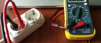
Dim light from lighting fixtures or the refusal of the washing machine to perform its functional duties indicates a possible drop in the supply voltage below normal. In such cases, it is necessary to measure the voltage, which will determine its compliance with the specified rating of the electrical network.
The same procedure is performed when repairing electronic devices, where the voltage drop on radio components and individual sections of the circuit is measured. This procedure is performed quite easily, but without understanding the physics of the process and the specifics of taking measurements, a person risks not only damaging expensive equipment, but also getting electrical injury, so next we will look at the basic principles of measurement.
Peculiarities
The device in question combines several devices that connect differently to one section of the circuit.
In order to use it correctly and get a complete picture of the state of the electrical network or an individual outlet, you should know at least some theory. At a minimum, you should understand how you can measure voltage, and how exactly you can measure current, and how you can correctly connect this or that device. When the cables are connected to a working power source, they receive an electrical voltage measured between zero and phase. To put it simply, it’s “– + “and” – “. The voltage in a standard electrical network can be measured both without a load connected to the electrical network and with it present.
There may also be a ground connection in the outlet.
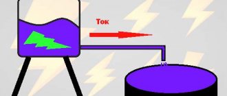
But the current itself appears only when the circuit is closed. Only after this does it begin to strive to move between the poles. In this case, measurements should be carried out exclusively when the device is connected in series. To measure the magnitude of the current, you should first let it pass through the multimeter.
To ensure that the multimeter itself does not distort the current strength and displays the most accurate data, its resistance should be kept to a minimum. If it is set to the current measurement mode, and at the same time you try to measure the voltage with it, then the result will be a simple short circuit. Although modern models do not have this problem, and voltage and current measurements are made using the same terminal connection. But it won’t hurt to remember some knowledge from the physics course. According to them, the same voltage will be observed in sections of the electrical circuit connected in parallel, and the current strength will be the same only when the conductor connection is in series.
In order to avoid errors and inaccuracies, before starting measurements, you should analyze the markings on the contacts of the multimeter and the mode switch. Note that in domestic conditions several groups of electrical networks are used . The most commonly used system in modern homes is a system with a voltage of 220 volts at a frequency of 50 hertz. Usually it consists of two elements - zero and phase. And the outlet itself plays the role of an exit.
In recent years, in newly built houses, a different power supply circuit has been installed - three-phase. Its difference will be a higher voltage at 380 volts. This makes it possible to power more powerful devices that do not work correctly in traditional systems. At a minimum, for this reason, the rated voltage in the outlet should be measured in order to simply understand whether it is possible to connect some powerful device to the outlets and the wiring capabilities to withstand the load created by the device.
In addition, voltage measurements will be required in other cases:
- if you need to check the operation of power cables;
- if it is necessary to check the functionality of a switch or socket;
- if the light bulb in the chandelier does not light up, although it is known that it is operational.
The ability to use a multimeter yourself will be an excellent opportunity to save on calling a technician.
And if there is information about unstable power supply, it will be possible to protect household appliances from failure by purchasing voltage stabilizers.
A little theory - how measuring instruments are connected
An electronic multimeter combines several different devices that are connected to a section of the circuit in different ways. To use it correctly, you need to know how voltage is measured, and how current is measured, and connect the device correctly.
When the wires are simply connected to a working power source, an electrical voltage appears on them, which can be measured between plus and minus (phase and zero). This means that the voltage can be measured both with a load (operating device) connected to the network and without it.
Electric current appears in the wires only when the circuit is closed - only then does it begin to flow from one pole to the other. In this case, current measurements are carried out when the measuring device is connected in series. This means that the current must pass through the device and only in this case will it be able to measure its value.
Of course, in order for the measuring device not to influence the current it measures, the resistance of the multimeter should be as low as possible. Accordingly, if the device is configured to measure current, and you mistakenly try to measure voltage with it, a short circuit will occur. True, not everything is clear here either - current and voltage measurements with modern electronic multimeters are carried out with the same connection of the terminals to the device.
If you recall at least superficial school knowledge about electrical circuits, then you can formulate the rules for measuring voltage and current as follows: the voltage is the same on parallel-connected sections of the circuit, and the current is the same when the conductors are connected in series.
To avoid errors, before taking measurements, be sure to check the markings located near the contacts of the multimeter and its mode switch.
Preparatory stage
Before you check the voltage in the outlet using a multimeter, you should do some preparatory work. To calculate voltage in different cases, different methods of supplying current in devices and systems are used. For example, there is alternating current in the outlet. At the same time, in accumulators or batteries the current is constant. For this reason, testers provide different operating modes. Before you start working with a certain device or system, the device must be switched to the desired mode.
Additionally, each instrument will have a specific flux in voltage measurement . And if this characteristic is unknown in advance, then the lever should be moved to the maximum position. You should also recall the purpose of the connectors located on the multimeter. The “10ADC” connector is needed to determine the DC current characteristics. The maximum allowed value is then 10 amperes.
Only the red probe is inserted here, that is, a plus.
The connector with the word "COM" is generic. Only a black probe, that is, a minus, is connected here to carry out measurements. The “VΩmA” connector is intended for various types of measurements. We are talking about resistance, voltage, current.
To carry out the work, the correct wire connection must be made. The red probe is connected to “VΩmA”, and the black one to “COM”. After this, you should move the control lever to the desired operating mode. To find out the voltage, the lever must be set to the abbreviation “ACV” or “V~”. Moreover, the position of the wheel should be set so that it is at a mark that will be higher than the expected voltage. For a regular power point, the standard is usually 220 volts. That is, it is necessary to set the nearest larger value. For most tester models, this value is 750 volts.
If the user does not even know the expected voltage and it is higher than the specified value, then this can lead to problems. The minimum would be failure of the multimeter, and the worst would be burns to the user’s hands. So before making the necessary measurements, it is better to calculate the network parameters.
Connecting plugs
Before measuring voltage, the multimeter must be set to the appropriate mode. To mark voltage, either the abbreviations ACV - alternating, and DCV - constant, or pictograms that complement the designation V - voltage are used. Yes, V
- this is alternating voltage. V with a horizontal long line, under which there are three short ones - this is a constant.
If your meter only has a V symbol on it, then it is capable of automatically detecting whether it is variable or constant.
In addition to pictograms indicating the type of voltage, ranges of values are marked on the multimeter body. Most household appliances have measurement limits of up to 750 V AC and up to 1000 V DC.
The black probe is either negative or zero. It is always installed in the multimeter socket marked COM. The red probe is either positive or “phase”. To connect it, select a socket equipped with appropriate markings. If there are only 2 slots, the question is removed; if there are more, choose the one with the V symbol next to it.
Other sockets can be marked either 10-20A or mA - respectively for measuring current strength (extra-high or ultra-low), or have other designations and, accordingly, purposes. There is always one voltage socket.
Standard indicators of the home electrical network
Before checking the voltage in the outlet with a multimeter or using the same device to find out the current strength in the extension cord, it is important to know what parameters to focus on for comparison.
The main indicators of the home electrical network are presented in GOST 32144-2013. Moreover, in addition to data that is incomprehensible to the average user (deviation from frequency, non-sinusoidal oscillations, lack of voltage symmetry in a three-phase network), it also indicates more understandable things:
- powered by alternating current with an oscillation frequency of 50 G;
- standard voltage and its permissible deviations - for residential and public premises for non-industrial purposes, 220 V is accepted with a permissible deviation of up to 10%, for more powerful consumers - a three-phase network with a voltage of 380 V;
- permissible rated current in the consumer - 6, 10, 16, 25, 32 A. Sockets and switches designed for a current of 6...16 A are intended for domestic purposes, 25 A - for devices with high energy consumption, 32 A - for three-phase circuits industrial value.
In this case, in the simplest ways - by plugging the device into a socket, turning on a toggle switch - you can only establish the presence of current in the network, but not the magnitude of its strength and voltage. The so-called “probes” also work—screwdrivers with a light or sound indication that is triggered upon contact with active wiring.
For a more detailed and competent study of the state of the electrical network, special multifunctional devices are used - multimeters.
Conclusions and useful video on the topic
The video will clearly demonstrate the sequence of actions when taking measurements in dynamics:
The article clearly explains how to measure voltage and current in an outlet for everyone who knows and is just getting acquainted with electrical outlets and electrical wiring. Using a multimeter will significantly reduce the likelihood of dangerous situations occurring when installing and repairing wiring, replacing sockets and switches.
Do you have some interesting information to share about using a multimeter? Did you have any questions while reading the article? Please write comments in the block intended for feedback.
How to check voltage with a multimeter
The thematic article “How to use a multimeter: detailed instructions for beginners” will help you understand the general principles of operation of the device. Here we will talk about using the device to work with sockets and other household electrical appliances.
The simplest multimeters used for household needs “can” measure current, voltage and resistance for AC and DC devices. If you need to check the voltage in a 220 V socket with a multimeter, the device regulator is set to the “alternating” voltage measurement area, marked V~ or ACV (depending on the multimeter model). In this case, taking into account the possible excess of voltage in the network of standard indicators, the regulator is set to the maximum value - 750 V. After turning on the device, the display should show three zeros (depending on the number of digits of the device - there can be from 2.5 to 8.5 - the number of zeros may differ).
Next you need to connect the probes. They are mounted like this: black in a socket marked COMMON (COM), red - or in a socket marked VΩmA.
Important: to make it easier to navigate the symbols on the front panel of the multimeter, we recommend studying the standard marking options.
The probes are installed in both sockets of the socket. The display will show the AC voltage value at that point in the network. If, when asked how to measure the voltage in a socket with a multimeter, the user is “stuck” on the choice of which hole to insert which probe into, we can reassure you. This is not important; in most modern instruments, the polarity of the probes when measuring voltage is not important.
Important: if you need to clarify how to measure the voltage with a multimeter in the socket of a low-power extension cord or in an old, Soviet-style electrical network, you can install the positive probe in the socket marked mA. In this case, overloading the device is practically eliminated.
Functional elements of a multimeter
Modern manufacturers produce various models of multimeters. Digital instruments with various additional functions, which are considered more accurate, are widely popular. An error of up to those percentages is considered normal. The lower the deviation indicator, the more reliable the test check.
Even the simplest electrical measuring device is capable of determining the most standard values - current, voltage and resistance. More expensive multimeters are equipped with special sensors for measuring temperature. Also, using such a hand tool, capacitance, intervals between pulses, frequency and inductance are determined.
Among the functional capabilities of the multimeter are:
- Recognition of disturbances in the operation of an electrical circuit. The device is capable of detecting the resistance value, which has fallen below the required scale, using a sound signal - “diagnosis”.
- Checking semiconductor elements. Using a multimeter, you can check diodes, transistors or thyristors, namely their serviceability.
- Many advanced models are equipped with displays that receive a signal and can carry out the necessary calculations.
The most popular additional features are:
- recording of the detected value by the device - push-button or automatic;
- illumination of indicators on the screen;
- power failure counter;
- reboot indicator;
- automatic detection of measurement boundaries.
In professional models, the minimum accuracy error is established. Sometimes digital processing ability is used. The necessary maximum parameters are fixed in the working memory, with the help of which the device calculates the average value.
Also on the front side of the multimeter there is a “continuity” icon and a knob for switching ranges
Almost all multimeters have catchy symbols that display the functional elements of the device:
- “DCA” – direct current measurement;
- “Ω” – resistance icon;
- “ACV” – constant voltage indicator;
- “DCV” is a designation for alternating voltage.
Some electrical measuring devices have two indicators at once - digital and dial. To make it easier to work with the device, two measuring scales are used, which allow you to measure in different values.
Digital multimeter: how to use?
The procedure from the moment of preparation is as follows:
- Set the preliminary range of the measured parameter. It is necessary to play it safe and put the switch in a position 10-15% greater than the expected one. In this case, even if it is exceeded, the multimeter fuse will not fail.
- Connect the cords to the connectors. Make sure that the red (negative) one is inserted into the socket that matches the type of value being measured. At the same time, the black (positive) is connected to the common COMMON (COM) connector.
- Bring the bare ends of the probes to the contacts of the circuit or part being tested. Be sure to hold the insulating layer with your fingers. The black probe is connected to the negative section, and the red one, respectively, to the positive section.
- Record the readings shown on the display. If the excess turns out to be excessive, move the rotary switch handle to a position corresponding to a lower range of the measured parameter.
Make sure that the multimeter measures exactly the value that is required in this particular case. Before switching buttons and handles, remove the probes and then touch them again to the bare contacts as described above.
Multimeter accuracy
For any multimeter, the instructions describe the characteristics, which say how much the measurement result may differ from the actual value. The digit capacity of the indicator matters. For the simplest devices it is 2.5. For precision ones, this characteristic is higher and equal to 8.5. By bit depth we mean the ability to display the result from 0 to 9 in full.
In an example it looks like this. If the digit is 3.9, the tester is capable of outputting data from 0.000 to 1.999 inclusive without switching modes. Otherwise, additional simple setup is required.
But this concerns ease of use. The accuracy of the multimeter depends on the discharge only indirectly. However, the connection is obvious. If you take a device with a bit depth of 2.5, deviations are possible within 10% in the direction of increase or decrease.
For professional work, electronics engineers buy testers with a 4.5 rating. Then the maximum error is only 0.1%. More expensive devices allow you to measure the parameters of the circuit and electrical components with a deviation of 0.01% from the readings displayed on the indicator (screen, monitor). Portable devices have a lower accuracy class than stationary, non-portable devices.
What if it’s not plugged in?..
Typically, all studies of household electrical networks, as already mentioned, are carried out through accessible points - sockets and switches. But from time to time it becomes necessary to check the wiring parameters where either sockets have not yet been installed (dismantled), or for some reason this is inconvenient/impossible. A good example is new buildings with “construction renovation”, where the wiring has just been installed in the apartment and there are no electrical appliances in sight except the meter.
If you need to know how to check the voltage in a 220 V network with a multimeter and still get the correct data, it is important to remember:
- the easiest way is to check the data in those places where sockets are planned to be installed or they have already been removed - there are two wires here, when connected to which the required characteristic is determined;
- mixing up the probes is not a problem. If the polarity is incorrect, the display will show the voltage value with a “-” sign;
- The main safety rule is not to touch the metal parts of the probes with your bare skin when they are in contact with the socket/wiring, and do not connect the probes in this position.
Often, beginners also ask how to check the battery voltage (on the battery) with a multimeter. In this case, the procedure is similar, but you should take into account:
- different characteristics of the electrical network and the battery - unlike household wiring, the current in the battery is constant. Consequently, the device regulator is set to the area marked DCV (V-);
- compared to the mains, the battery voltage is much lower - 1.5...24 V. Therefore, there is no need to set the regulator to the maximum value of the measured range;
- The polarity of the probes also does not matter, but it is easier to connect the red (positive) contact to the positive output of the battery, and the negative (black) contact to the negative one.
The concept of polarized and non-polarized plug
There are two types of single-phase sockets used in everyday life.
Non-polarized socket
These are devices into which the plug can be inserted in two ways - straight and rotated 180°. Such sockets are used to connect electrical appliances in which the polarity of the connection does not matter.
Non-polarized plugs and sockets with and without grounding are used in most European countries, in the former USSR and in some other countries.
Polarized plugs and sockets
These devices can be turned on only in one position and supply “zero” and “phase” to the electrical device through certain wires. In devices connected using such plugs, protective switches are installed only on the phase wire.
There are different types of polarized sockets that are used in different countries:
- In France and some other countries in Europe, Asia and Africa, standard connectors are used - CEE 7/5. In these connectors, the pin contacts are arranged in a triangle, in which the ground electrode is located at the obtuse corner of the triangle.
- English Standard BS 1363. British 3-prong plugs have three flat prongs - two horizontal for power and one vertical for earth.
- American standard NEMA 5-15. The North American 3-pin plug has two flat pins parallel to each other to supply power. At the third vertex of the triangle there is a round pin for connecting to ground.
In addition to those listed above, there are other, less common types of polarized plugs and sockets.
Advice! An American, French or other type of plug can be connected to a regular European socket through an adapter.
Security measures
Now let's talk about safety measures that you should know when carrying out this type of work. The first thing you should know is to avoid touching the parts with your fingers. The fact is that the human body has resistance, which will affect the accuracy of measurements and can distort them. Another aspect is that if the master does not have information about the pre-voltage in the network, then you can measure the indicators so that the control wheel is set to the highest value in volts.
In addition, it is best to carry out work wearing special dielectric gloves . Although ordinary rubber or household ones may be suitable. When determining line resistance, it is best to ensure that the power is completely turned off and the capacitors are completely discharged.
In addition, when working with a 20-amp power point, measurements should be taken no more than a quarter of a minute. Also, you should not check the network performance with a tester if the room humidity is high . In addition, the control wheel must not be turned under any circumstances while taking measurements. Also, you should not use the device if the braiding of the probes is deformed and there is serious damage to the body.
The battery of the device should be replaced only after the wheel has been switched to off mode. After this, the used battery is disposed of. Under no circumstances should it be thrown away with household waste. When measuring the internal resistance of a circuit, make sure that it is not energized so that the tester is not damaged. There are standards for the operation and storage of such a precision instrument as a multimeter. Do not apply voltage to the device if the rotary type lever is at “Ohm”.
In addition, the device in question should not be used if the housing cover is not securely or completely closed.
An equally important aspect is that replacing a galvanic-type battery should be done not only when the device is turned off, as mentioned above, but also when all probes are disconnected from the multimeter sockets. Measuring the voltage in an outlet with a multimeter is a rather responsible process. The person who is going to carry it out must have certain theoretical and practical knowledge, as well as take into account certain standards and requirements that are put forward for the equipment.
But, nevertheless, with all the necessary knowledge of a theoretical and practical nature, even a person who has never done anything like this before can carry out this type of measurement . The main point will be the correct setting of the expected characteristics of the electrical network, because it is this aspect that most often leads to equipment breakdowns, since users do not pay due attention to it. Therefore, we should once again recall the importance of this particular component.
Screwdriver indicator
To determine the phase in the socket, you can use a tester screwdriver. This is a small device in the form of a regular screwdriver with a transparent handle, which has a built-in LED light bulb. When the operating circuit is closed, it lights up, indicating the presence of voltage. At the end of the handle there is a contact plate for determining 0.
Test rules:
- Holding the screwdriver carefully in your hand, insert the tip into the socket of the socket.
- If there is phase, the LED indicator inside the transparent handle will light up. If there is no light, then this is a neutral conductor.
- To check if there is current in the circuit, place your finger on the end. The circuit will close and the indicator will work.
Using such an indicator screwdriver it is impossible to set the numerical value of the potential, but it is quite enough to determine a break. A screwdriver with advanced functionality has much more capabilities. This miniature device has a switch with 3 modes:
- O - for contact determination of voltage, if present, the red diode lights up;
- L - for contactless operation, when approaching a phase the green light is on;
- N - for working using a non-contact method with high sensitivity, in addition to the green diode, the signal is generated by an audible buzzer.
The choice of mode is determined by the possibility of open contact with conductors, as well as the circuit resistance. For O it should be no more than 5 mOhm, for L and H - 50 and 100 mOhm, respectively.
There is a metal plate on the side of the indicator screwdriver body. During contact work, you do not need to touch it to determine the phase. If a continuity test is performed, then in the O mode the sting touches the contacts, and the finger is placed on the plate, forming a jumper in the circuit. If the circuit is intact, the red indicator lights up. In this way, not only sockets are checked, but also incandescent lamps, heating elements, switches and other devices.
Why know the voltage in the outlet?
The outlet is carrying alternating current. This means that deviations from the nominal value occur, up or down. The nominal voltage in Russia is considered to be 220 Volts, but in fact the value is 230 Volts. Modern household appliances are created taking into account permissible deviations; exceeding the specification can cause damage to the devices. Devices with electric motors (air conditioners, refrigerators) are especially susceptible to influence. To reduce the risk of breakdown, you need to be able to determine voltage using special testers.
Many people believe that this skill is not necessary for the average user and is only needed by specialists. This is not so, because fixing the socket, checking the presence of a network in the apartment and other work related to wiring begins with determining the voltage.
Which wire can you touch in a live socket? Phase or zero?
Since we are in the electrical safety section, we will also discuss the issue of touching the neutral and phase wires in the socket. Electricity will not be disassembled by accident or on purpose, the result will be the same.
We immediately touched the phase and zero
A current flowed through you of the same magnitude as U/R. Where R is your internal resistance, which depends on various factors. That is, the current will flow and you will be sad or posthumous. There are several ways current flows through a person.
Touched the phase conductor:
If you are soaring in the air like a bird or standing on a dry wooden stand, plus you don’t touch grounded objects with other parts of your body, plus a bunch of other factors that you “took into account” (although most likely you didn’t take into account, but circumstances just happened that way) => Then you will not will give you an electric shock.
Note: Let's assume that the situation was such that you survived. And you tell everyone that this is how you can do it. Someone will listen to you and repeat, but with a sadder outcome. Either because of a wet floor or hands, or because of accidental contact with a grounded equipment case. This means that you doomed a person to disaster, only because you used the “survivor effect”. Is not cool.
Touched the working zero:
Nothing will happen to you only if the load in the network is symmetrical in all three phases, and the current does not flow in the neutral wire (more about neutral displacement), and this is a rare case that can sometimes occur in production.
It is always easier to turn off the power and carry out the necessary work than to put your life at risk. As they say, safety rules are written in blood. But I do not deny that there were people who took up the phase and neutral wires and got nothing. Simply playing with electricity will not lead to anything good. It's like walking blindly through an unmarked highway at night.
Personally, I always use the following rule: if you want to tinker with sockets or switches in the apartment, turn off the input circuit breaker and make sure that no one turns it on.
What will it show if the socket is faulty?
If there is no network, the multimeter will read 0 Volts. The reason is a faulty socket or lack of electricity. To determine the cause, you need to ring other outlets in the room. If only one does not work, its contacts are checked and, if necessary, replaced with a new one.
During voltage surges, the values on the multitester will differ greatly from the nominal 220 Volts. According to GOST, a deviation of 10% is permissible; a larger deviation can lead to damage to electrical appliances. If a strong voltage surge is detected, it is worth installing an additional stabilization device in the apartment.
The home network operates at a voltage of 220 Volts, but in the outlet it may differ from the nominal value. Voltage within the limits established by GOST is the key to high-quality and stable operation of household appliances. It is important to be able to check voltage using a multitester to prevent the risk of damage to electrical devices. If there is a significant deviation from the set values, care should be taken to stabilize the voltage in the room.
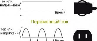
Difference Between AC and DC Voltage
It would be more correct to talk about the difference between direct and alternating current. Various electrical appliances operate on either direct current or alternating current.
Variable means that the direction of movement of electrons in a conductor changes from plus to minus with a given frequency, that is, the polarity of the current changes. In a household outlet, according to the standard, the effective voltage is 220 V (amplitude 311 V) and the frequency of current change is 50 Hz. All devices that are plugged into an outlet operate from this voltage.
But accumulators and batteries are sources of direct current. They always have a fixed plus and minus (polarity). Naturally, direct current has no frequency.
Connecting probes to a multimeter
Probes are a special type of connectors that help measure the characteristics of electrical parts and sections of a wire circuit. They easily connect the necessary connectors of the multitester with other outputs.
Usually they are a metal rod with plastic insulation, at one end of which the rod exits from the other - a wire with a connector for insertion into the 20A, A, COM and VΩ connectors of the device.
In addition, sometimes it is necessary to have an additional set of probes in your arsenal, but instead of a rod, metal “crocodiles” are used - toothed clamps.
“Crocodile” is a special type of attachment for multitester probes, very convenient for measuring the electrical characteristics of medium and large parts
Most devices are imported from China, where they are manufactured in factories, workshops and mini-workshops. In this regard, manufacturers save on everything, including materials for probes, which quickly fail.
It is recommended to make the probes yourself by purchasing parts on the radio market or in a radio store. Instead of insulating plastic, empty ampoules and casings for ballpoint pens are often used.
The COM connector is an electrical “minus” and performs the grounding function in all modes and ranges. Usually a black probe is connected here
We connect the plug of the black probe into the multimeter connector marked COM. And we connect the plug of the red probe into the connector marked VΩ, which is designed for measuring direct and alternating voltage.
We strongly do not recommend pressing the red and black probes onto the contact in any mode, with the exception of the rotary switch in the “►” position (chain continuity).
In addition to voltage, the multitester can measure current and resistance values. It is important to remember that when measuring resistance values, you must turn off the power
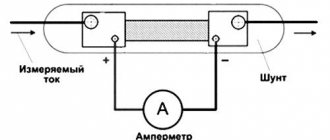
Measuring AC current with a voltmeter
If you need to measure the strength of alternating current, but you only have a budget multimeter at hand, which does not have such functionality, then you can get out of the situation by using the measurement method using a shunt. Its meaning is reflected by the formula I = U / R, Where I is the current strength that needs to be found, U is the voltage in the local section of the conductor, and R is the resistance of this section. From the formula it is clear that if R is equal to one, then the current strength in the circuit section will be equal to the voltage.
To measure, you need to find a conductor with a resistance of 1 ohm - this can be a fairly long wire from a transformer or a piece of spiral from an electric stove. Wire resistance, i.e. its length is adjusted by the tester in the appropriate test mode.
The result is the following circuit (incandescent lamp as a load):
- From the first connector of the socket, the wire goes to the beginning of the shunt, and one of the multimeter probes is connected here.
- The second probe of the multimeter is connected to the end of the shunt and from this point the wire goes to the first contact of the lamp base.
- From the second contact of the lamp base, the wire goes to the second connector of the socket.
The multimeter is set to AC VOLTAGE MEASUREMENT MODE. It is connected in parallel to the shunt, so all the rules are followed. When the power is turned on, it will show a voltage equal to the current passing through the shunt, which in turn is the same as the load.
Resistance measurement
Typically, the resistance measurement range of a multimeter is divided into five ranges:
Most multimeters have another range, indicated by a diode or buzzer icon - this is intended for checking contact. When the contact is closed, the LED lights up and a signal sounds. In some types of multimeters, this function is performed by the 200 Ohm range.
In everyday life, resistance measurement is usually used to check for breaks in the electrical circuit, as well as the serviceability of some household appliances, for example, light bulbs, an iron, electric motor windings, etc.
By measuring resistance, you can check the serviceability of the fuse, the functionality of the switch and other switching devices.
If one appears on the left side of the display, it means that the resistance of the measured circuit is higher than the included range; you need to switch to the next one. A unit in all resistance measurement ranges indicates the presence of an open circuit.
How to Measure Battery or Battery Voltage
All kinds of batteries and various accumulators, in general, everything where you see “+” and “-” are all sources of direct electric current. Measuring DC voltage is no more difficult than alternating voltage.
To do this, take, for example, the most ordinary AA battery. Connect the red wire of the multimeter to “+” terminal of the battery, and the black wire to the “-” terminal of the battery . If you connect them the other way around, nothing bad will happen, the readings will simply be displayed on the multimeter screen with a minus sign, something like this.
Usually the voltage on the batteries is low, so you don’t have to be afraid to press the probes with your fingers. Up to 20 volts you most likely won't feel anything. In the case of an AAA battery, its maximum voltage is 1.5 volts, which is not at all dangerous for a person.
As we can see from the multimeter readings, the voltage in our battery is 1.351 volts, which means the battery is still fully charged and can be used.
In a similar way, you can check any other batteries and measure their voltage, and as you now know, there is nothing complicated about it.
Voltage measurement
Usually in this case the task is to measure the voltage in the outlet or simply check its presence. The first step is to prepare the tester itself - the black wire is inserted into the terminal marked COM - this is negative or “ground”. The red one is inserted into the terminal, which has the letter “V” in its designation: it is often written next to other symbols and looks something like this ֪– VΩmA. Near the multimeter mode selection wheel, the limit values are shown - 750 and 200 Volts (in the section marked ACV). When measuring the voltage in the outlet, the voltage should be about 220 Volts, so the switch is set to the 750 division.
Zeros will appear on the device screen - the device is ready for use. Now you need to insert the probes into the socket and find out what voltage is in it now and whether there is any voltage at all. Since it is necessary to measure the voltage in the AC network, it makes no difference which probe touches the phase and which zero - the result on the screen will be unchanged - 220 (+/-) Volts if there is voltage in the outlet or zero if there is none. In the second case, you need to be careful - if there is no zero in the socket, the device will simply show that the socket is not working, so in order not to receive an electric shock, it would not hurt to additionally check the contacts with a voltage probe.
DC voltage is measured in exactly the same way - the only difference is that the probe with the black wire must touch the minus, and the red wire must touch the plus (if they are correctly connected to the terminals of the device). The mode selection wheel, of course, must be moved to the DCV area.
There is the same nice feature here as when measuring alternating voltage: in fact, when determining the voltage, you can touch both minus and plus with the black probe - just if you reverse the polarity, the correct result will be displayed on the device screen, but with a minus sign.
These are all the features that you need to know before measuring the voltage with a multimeter - in any device or outlet.
Checking the diode with a multimeter
The diode only conducts current in one direction, so two measurements will be required to check for functionality. In the first position there is conductivity, in the second there should not be. A breakdown is indicated by two cases when the current does not flow in both directions or vice versa, if the readings are zero in any of the cases. When checking, the handle is moved to a position whose range satisfies the nominal characteristics of the diode being tested.
Analogues of the Duwi and KVT socket testers - which is better?
Other manufacturers also have similar testers. For example duwi or KVT MS686ODR.
However, they lack the ability to check voltage. Sockets are tested in the same way.
You plug in the tester and by the flashing indicators you get the information you are interested in. Fortunately, everything on these testers is written in Russian and there is no need to translate anything.
For example, checking the carry.
As you can see, the middle LED is blinking. This means that there is no grounding in the carrier. Unfortunately, this picture occurs all the time. Therefore, when choosing extension cords, be extremely careful.
Unfortunately, the functionality of similar devices from KVT and other manufacturers is slightly limited and they lack a voltage display. And this is perhaps the main thing that interests the average consumer.
You can get acquainted with an adequate price and order such a miracle Habotest tester from our Chinese comrades here.
Tester operating instructions (in English)
As a result
Even a budget universal measuring device - a multimeter - allows you to take measurements within a fairly wide range, sufficient for home use. But when buying a device, you need to at least have a general idea of what purposes it will be used for - it may be better to overpay a little, but as a result, have a tester on hand that can perform any task assigned to it. Also, before using it, it would not hurt to at least in general refresh your memory of the basics of constructing electrical circuits and using electrical measuring instruments in them.
Sources
- https://stroy-podskazka.ru/multimetr/proverit-napryazhenie-v-rozetke/
- https://stroy-okey.ru/house/instrument/kak-proverit-naprjazhenie-v-rozetke-multimetrom/
- https://instanko.ru/instrumenty-i-materialy/tester-elektricheskij-multimetr-instrukciya-2.html
- https://electric-220.ru/kak-proverit-naprjazhenie-multimetrom
- https://pomegerim.ru/electrobezopasnost/sila-toka-v-rozetke.php
- https://domikelectrica.ru/kak-proverit-rozetki-v-kvartire/
- https://YaElectrik.ru/elektroprovodka/kak-proverit-napryazhenie-v-rozetke-multimetrom
[collapse]
Similar posts:
- Calculation of cable cross-section by power: formulas, tables,…
- Location of sockets in the kitchen: diagram with dimensions,…
- Connecting the hob to the power supply yourself
- How to connect a phone socket yourself
- Triple socket: installation diagram, with and without grounding,…
- Oven socket: what kind of socket is needed for...