Hello. It is difficult not to find information on this topic, but I will try to make this article as complete as possible. We will talk about such a topic as the connection diagram for a three-phase 220 volt motor and the connection diagram for a three-phase 380 volt motor.
First, let's understand a little what the three phases are and what they are needed for. In ordinary life, three phases are needed only to avoid laying large cross-section wires throughout the apartment or house. But when it comes to motors, three phases are needed to create a circular magnetic field and, as a result, higher efficiency. Motors are either synchronous or asynchronous. To put it very roughly, synchronous motors have a large starting torque and the ability to smoothly regulate speed, but are more complex to manufacture. Where these characteristics are not needed, asynchronous motors have become widespread. The material below is suitable for both types of motors, but is more relevant to asynchronous ones.
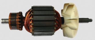
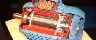
What you need to know about the engine? All engines have nameplates with information indicating the main characteristics of the engine. As a rule, motors are produced for two voltages at once. Although if you have an engine with one voltage, then if you really want to, you can convert it to two. This is possible due to a design feature. All asynchronous motors have a minimum of three windings. The beginnings and ends of these windings are brought out into the BRNO box (switching (or distribution) unit for the beginning of the windings) and, as a rule, the engine passport is inserted into it:
If the motor has two voltages, then there will be six terminals in the BRNO. If the motor has one voltage, then there will be three pins, and the remaining pins are connected and located inside the motor. We will not consider how to “get them” from there in this article.
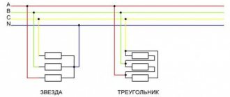
So, which engines are right for us? To turn on a three-phase 220 volt motor, only those with a voltage of 220 volts, namely 127/220 or 220/380 volts, are suitable. As I already said, the motor has three independent windings and, depending on the connection diagram, they are capable of operating at two voltages. These schemes are called “triangle” and “star”:
I think there is no need to even explain why they are called that. It is necessary to note that windings have a beginning and an end and these are not just words. If, for example, it doesn’t matter to a light bulb where to connect the phase and where the zero is connected, then if the connection is incorrect, a “short circuit” of the magnetic flux will occur in the motor. The engine will not burn out immediately, but at a minimum it will not rotate, at most it will lose 33% of its power, begin to get very hot and, ultimately, burn out. At the same time, there is no clear definition of “this is the beginning” and “this is the end.” Here we are talking more about the unidirectionality of the windings. I'll give you a small example.
Let's imagine that we have three tubes in a certain vessel. Let's take the beginnings of these tubes as the designations with capital letters (A1, B1, C1), and the ends with lowercase letters (a1, b1, c1). Now, if we supply water to the beginnings of the tubes, then the water will spin clockwise, and if to the ends tubes, then counterclockwise. The key word here is “accept.” That is, from whether we call the three unidirectional outputs of the winding the beginning or the end, only the direction of rotation changes.
But this is what the picture will look like if we confuse the beginning and end of one of the windings, or rather not the beginning and end, but the direction of the winding. This winding will begin to work “against the flow”. As a result, it does not matter which output we call the beginning and which the end, it is important that when applying phases to the ends or the beginning of the windings, the magnetic fluxes created by the windings do not short-circuit, that is, the direction of the windings coincides, or more precisely, the direction of the magnetic fluxes , which create the windings.
Ideally, for a three-phase motor it is desirable to use three phases, because capacitor connection to a single-phase network results in a power loss of about 30%.
Well, now directly to practice. We look at the engine nameplate. If the voltage on the engine is 127/220 volts, then the connection diagram will be “star”, if 220/380 – “triangle”. If the voltages are different, for example, 380/660, then such an engine will not be suitable for connecting the engine to a 220-volt network. More precisely, an engine with a voltage of 380/660 can be turned on, but the power loss here will already be more than 70%. As a rule, on the inside of the BRNO box cover it is indicated how to connect the motor leads to obtain the desired circuit. Look again carefully at the connection diagram:
What we see here: when switched on by a triangle, a voltage of 220 volts is supplied to one winding, and when switched on by a star, 380 volts is supplied to two windings connected in series, which results in the same 220 volts per winding. It is due to this that it becomes possible to use two voltages at once for one engine.
There are two methods for connecting a three-phase motor to a single-phase network.
- Use a frequency converter that converts one phase 220 volts into three phases 220 volts (we will not consider this method in this article)
- Use capacitors (we will consider this method in more detail).
Connecting a three-phase motor to a 380V network
There are two basic schemes (video and diagrams in the next subsection of the article):
- triangle,
- star.
The advantage of a delta connection is that it operates at maximum power. But when the electric motor is turned on, high starting currents are produced in the windings, which are dangerous for equipment. When connected by a star, the motor starts smoothly, since the currents are low. But it will not be possible to achieve maximum power.
In connection with the above, motors when powered by 380 Volts are connected only by a star. Otherwise, high voltage when switched on by a delta can develop such inrush currents that the unit will fail. But under high load, the output power may not be enough. Then they resort to a trick: they start the engine with a star for safe inclusion, and then switch from this circuit to a delta for gaining high power.
Triangle and star
Before we look at these diagrams, let's agree:
- The stator has 3 windings, each of which has 1 beginning and 1 end. They are brought out in the form of contacts. Therefore, for each winding there are 2 of them. We will designate: winding - O, end - K, beginning - N. In the diagram below there are 6 contacts, numbered from 1 to 6. For the first winding, the beginning is 1, the end is 4. According to the accepted notation, this is HO1 and KO4. For the second winding - NO2 and KO5, for the third - HO3 and KO6.
- There are 3 phases in the 380 Volt electrical network: A, B and C. Let’s leave their symbols the same.
When connecting the windings of an electric motor with a star, first connect all the beginnings: HO1, HO2 and HO3. Then KO4, KO5 and KO6 are respectively supplied with power from A, B and C.
When connecting an asynchronous electric motor with a triangle, each beginning is connected to the end of the winding in series. The choice of the order of winding numbers is arbitrary. It may turn out: NO1-KO5-NO2-KO6-NO3-KO2.
Star and delta connections look like this:
Watch the video to help you understand how to connect the windings.
Transition circuit
To smoothly switch the 380 electric motor into a 3-phase power supply and high power output, it is started with a star. After overclocking, it automatically switches from the circuit and starts working as a triangle. The disadvantage of this method is the impossibility of changing the direction of rotation of the shaft.
The transition circuit involves connection through a magnetic starter (see also video). You will need 3 of these:
- The first one in the diagram is designated MP1 (magnetic starter 1). It connects the beginning of the stator windings HO1, HO2 and HO3 with the phases of the 380 Volt network: A, B and C.
- The second starter is MP2. It connects the ends of windings KO4, KO5 and KO6 with phase wires A, B and C using a triangle.
- The third starter is MP3. Necessary for connecting the ends of windings to a 3-phase star network.
Attention! Starter 2 and 3 cannot be turned on at the same time, because a short circuit will occur. In this regard, a protective shutdown will occur on the emergency panel. To prevent starter 2 from accidentally turning on at the same time as 3, an electrical interlock is required. Then the third magnetic starter will turn on only after the second one turns off. And vice versa.
Principle of operation:
- The first starter turns on;
- The time relay is triggered, which turns on the third magnetic starter (star start);
- After a specified time, the relay turns off the third and turns on the second starter (triangle operation).
The work is stopped by opening MP1. When you restart, steps 1-3 will be repeated.
Reversing circuit of an asynchronous motor
This method is based on changing the phasing of the supply voltage of the motor that supplies the stator windings. The engine reverse circuit, in contrast to the conventional control circuit (start and stop), contains not one, but two magnetic starters.
As can be seen from the diagram, their power contacts are connected in such a way that the operation of each magnetic starter will ensure the supply of supply voltage to the motor of different phasing.
The order of alternation of the phases supplying the electric motor when the KM1 starter is triggered will be as follows: L1, L2, L3, and when KM2 is triggered: L3, L2, L1. Changing the supply phases L1 to L3 and vice versa will provide different directions of rotation of the electric motor.
To start the electric motor in different directions, there are two start buttons in the circuit; pressing each will trigger a specific contactor. Depending on which starter triggered, the power phasing at the motor terminals will be L1, L2, L3 or L3, L2, L1.
To stop the electric motor, there is one “Stop” button in the power supply circuit for the coils of both starters, pressing which will interrupt the supply circuit to the coil of the triggered starter.
In order to avoid simultaneous operation of both starters due to erroneous pressing of the “start” buttons and to prevent the short circuit of the phase conductor L1 to L3, such operation is blocked in the control part of the proposed circuit based on relay logic.
When one of the magnetic starters is triggered, the power circuit of the coil of the other will be open by the normally closed contact of the triggered contactor, connected in series to this circuit.
- home
- Electrical circuits
- Reversing an asynchronous motor
Connecting a three-phase motor to a 220V network
Connecting a three-phase motor to a single-phase network is just as possible as connecting it to a three-phase network. The only difference will be in the connection method and the operating power produced by the motor. It cannot exceed 50% of the maximum value achieved when powered from a 380 Volt network if the windings are connected with a star. When connected using the delta method, 70% of the maximum possible power can be developed. Therefore, if the power is supplied from a 220V network, it makes sense to connect the electric motor only in the second way.
Attention! If the voltage in the electrical network is 220 Volts, then the currents at startup do not reach critical values even when connected in a triangle. Therefore, this scheme is optimal.
Motor connection diagram 380 to 220
When powered by 380, there is one phase per winding. But when connected to 220 Volts, the phase and neutral wires are connected to two windings, the third remains free. To compensate for the absence of the third phase, the electric motor starts through a capacitor.
Important! You can start a 380 Volt motor from a voltage of 220V only using capacitors. Without them, only engines designed to be powered by 220 initially can operate.
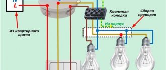
If a low-power motor (no more than 1500 W) is started without an initial load, then it can only be connected through a working capacitor. There are two wires coming from it. The first one needs to be connected to zero, and the second one to the 3rd vertex of the triangle.
Attention! If you need to reverse the direction of rotation of a motor connected to a 220 Volt network, then connect the first terminal from the capacitor not through zero, but through a phase wire.
When starting a powerful asynchronous motor (from 1500 W) or when starting a low-power one, but with an initial load, connect it to 220V through the operating and starting capacitors. The latter is connected in parallel to the first. It is necessary to increase the starting torque, so it is turned on only at the moment the motor is started.
The starting capacitor is connected to the circuit through a button, and 220V power is supplied by moving a special toggle switch to the “on” position, and turning it off to the “off” state. Instead of a toggle switch, you can use a button with two positions. Then the launch will be as follows:
- Power is supplied through a toggle switch or a special button;
- The capacitor start button is pressed;
- It is held until the electric motor accelerates;
- The start button is released, causing its springs to open the capacitor circuit.
When you turn on the electric motor in a 220-volt network with reverse, you will need another toggle switch to change the direction of shaft rotation. When changing position, one of the terminals of the working capacitor will be connected either to phase or to zero.
The figure above shows a diagram for connecting a 380 motor to a 220 network with reverse with a start button. It is relevant if the motor does not pick up speed in the absence of a starting accumulator (it is on the right in the figure).
Electric drive control circuits
Scheme for starting an asynchronous motor with a wound rotor using a magnetic station P. When the three-pole switch Q1, made in the form of a switch, is switched on, pressing the start button S2 leads to the connection of the coil of the linear contactor K1 to the power source and switching on by the main closing contacts K1. The circuit provides direct starting and reversing of the engine, as well as back-on braking during manual non-automatic control.
When the temperature drops to the set temperature, the DOT opens and the compressor turns off. Scheme of sequential connection of motors Example 5.
Rheostatic starting of an asynchronous motor with a short-circuit rotor. Point P is the starting point. One asynchronous low-voltage electric motor designed to drive the compressor.
Motor protection for reverse control is the same as for non-reversible control. When reversing the engine while moving, it first decelerates from a given speed to zero, and then accelerates in the other direction. If it is only necessary to brake the engine when it reaches zero rotation speed, the SВЗ button must be pressed again, which will lead to disconnecting the engine from the network and returning the circuit to its original position. Means for inhalation anesthesia: Anesthesia occurs as a result of inhalation of drugs, which is carried out or using a mask. It is enough to apply three-phase voltage to the engine stator and the engine starts immediately. The rotational speed of an asynchronous motor can be adjusted by changing the frequency of the supply network current, the number of pole pairs of the stator winding, and introducing a resistance into the rotor circuit, which causes an increase in slip. Magnetic starter control circuits
Connecting an electric motor via a magnetic starter
In principle, the connection diagram for a 3-phase motor through a magnetic starter is almost exactly the same as through a machine. It simply adds an on/off block with “Start” and “Stop” buttons.
One of the phases of connection to the electric motor passes through the “Start” button (it is normally closed). That is, when it is pressed, the contacts close and current begins to flow to the electric motor. But there is one point. If you release Start, the contacts will open and the current will not flow as intended.
Using a star-delta circuit
A combined connection diagram known as “star-delta” is used relatively rarely. It allows for a smooth start with a star circuit, and during the main operation a triangle is turned on, providing maximum power to the unit.
This connection diagram is quite complex, requiring the use of three magnetic starters installed in the winding connections. The first MP is connected to the network and with the ends of the windings. MP-2 and MP-3 are connected to opposite ends of the windings. The delta connection is made to the second starter, and the star connection is made to the third. Simultaneous activation of the second and third starters is strictly prohibited. This will cause a short circuit between the phases connected to them. To prevent such situations, an interlock is installed between these starters. When one MP turns on, the contacts of the other open.
The entire system operates according to the following principle: simultaneously with MP-1 being turned on, MP-3, connected by a star, is turned on. After a smooth start of the engine, after a certain period of time set by the relay, the transition to normal operating mode occurs. Next, MP-3 is turned off and MP-2 is turned on according to a triangle diagram.