In the world of the seemingly victorious alternating current, no, not a revolution is brewing, but an organic evolution: direct current is not just returning, but is laying claim to the laurels of the winner. Investments in renewable energy and cross-border electricity transmission have made high-voltage DC grids more relevant than ever. In this post we tell you why direct current gave way to alternating current and how, a century after the “War of Currents,” direct current took its revenge.
Source: Shutterstock
Direct current is the basis of modern technological society: all semiconductor electronics, powered by mains or batteries, use direct current, with its help the extraction of pure aluminum, magnesium, copper and other substances. The vehicle's on-board network also has direct current, as does the electrical transmission of diesel ships. And of course electric trains: trams, subways and some electric locomotives are powered by direct current. And space: all man-made space objects function exclusively thanks to direct current from batteries or RTGs.
In addition to all this, there is another area where direct current, if not irreplaceable, is at least much more efficient than alternating current - high-voltage lines for transmitting high power. Direct current lines (HVDC, High-voltage direct current) a century ago became the salvation of high-voltage alternating current lines (HVAC, High-voltage alternating current). If it were not for direct current, the electricity in our outlets would be much more expensive and disappear more often than it does now. Let's understand this interesting story of “mutual assistance”.
The irony of DC
To appreciate the irony of the situation with the return of direct current to high-voltage power lines, you need to remember the events of the “War of Currents” - a battle between apologists for direct current represented by the inventor and businessman Thomas Edison and alternating current, the advantages of which were realized by entrepreneur George Westinghouse. Let's take a quick look at how DC lost the battle to become the backbone of the world's energy supply.
After humanity subjugated electricity and learned to benefit from it in industry, far-sighted businessmen realized that by electrifying cities in the future they could make not just capital, but a fantastic fortune. Inventor Thomas Edison was excellent at monetizing his talent as an innovator and made money not so much from his own inventions as from improving the ideas of others. One example of such a successful “fine-tuning” was the creation of an incandescent lamp, which appeared thanks to arc lamps with carbon electrodes that fell into the hands of Edison. Although such lamps provided light, they were not suitable as constant sources of lighting - in those days, carbon arc lamps worked for several hours at most, and they could only be turned on once.
Edison's first production lamp - still with a carbon filament and an operating time of several tens of hours. Source: Terren / Wikimedia Commons
Having improved the design and created his famous incandescent lamp, which could work for 40 hours, and after modification for 1200 hours, Edison realized that his light bulb could become the basis of lighting systems for cities and buildings - giving brighter light compared to candles and gas lamps, incandescent lamps had a lower cost, did not smoke, did not burn oxygen in the premises, and required replacement less frequently than the same candles. The production of lamps was undertaken by the Edison Electric Light enterprise, and the production of direct current generators by Edison General Electric. By selling lamps below cost, Edison conquered the lighting market, and began building power grids in London and New York for the first consumers.
An incandescent lamp can operate with both alternating and direct current, but Edison chose direct current. The reason for this decision is very trivial and far from physics. As we said, Edison was not only an inventor, but also a very enterprising businessman. He saw electricity not only as a way to cheaply illuminate cities, but also as an opportunity to modernize industry through the introduction of electric traction. The electric motors that existed at that time operated only on direct current.
In addition, in order to make money on electricity supplies, it was necessary to somehow measure the consumption of each subscriber. Edison created an individual meter, which was a reservoir with an electrolyte and a plate on which copper was deposited under the influence of a passing current - every month the plate was weighed and electricity consumption was calculated based on the difference in mass. Such a meter worked only with direct current.
DC meter designed by Thomas Edison. “Transfer of readings” consisted of handing over a jar of plates to representatives of the power company. Source: Thomas A. Edison Papers / edison.rutgers.edu
But direct current also had unsolved problems, the main one of which was the impossibility of transmitting high power over long (more than 2 km) distances. In order to transmit the high power that is necessary to power an enterprise or a city lighting system, either the current or the voltage must be increased in the electrical network (power, recall, is equal to the product of voltage and current). But at the end of the 19th century there were no ways to change DC voltage. Electrical appliances produced in the USA operated on a voltage of 110 V, so Edison's power plants, which operated on steam generators, had to send exactly 110 V to the network.
All that remained was to control the current strength. As the current increases, part of the energy is spent on heating the wires (there is no such problem with high voltage). To reduce losses and heating, you need to reduce the resistance by increasing the diameter of the conductor or using materials with good electrical conductivity, such as copper. And still, losses will increase depending on the length of the cable.
To reduce the length of the conductor to acceptable levels, consumers had to be located no further than 1.5-2 km from the power plant, otherwise the power in the network would drop to unacceptable values. For example, on the 56-kilometer line between the French cities of Creil and Paris, losses reached 45%. No matter how Edison struggled with the problem of losses in DC networks, he was never able to solve it. The only solution was to build low-power power plants near consumers. At that time it did not seem like an outrage against the environment and residents - these were precisely the stations that Edison’s company built. The first of these was built on Pearl Street in Manhattan, New York in 1882, the same year the installation of underground 110-volt DC cables began.
Edison laid underground power lines for street lighting even before it became fashionable in Moscow. The illustration shows the installation of a DC line in New York in 1882. Source: WP Snyder/Wikimedia Commons
Thomas Edison realized the error of his choice, although he did not publicly admit it, when his competitor in the electrical business, George Westinghouse, began investing in the construction of power plants and alternating current networks, which had serious advantages over direct current networks. Thanks to transformers that had already been invented by that time, alternating current voltage could be easily increased and decreased. Transformers solved the problem of transmitting high power, because instead of current, you could simply increase the voltage, the transmission of which did not require thick wires made of expensive copper.
In this way, Westinghouse networks could transmit very high power over cheap, smaller-diameter cables with virtually no losses. This is proven by the example of a 175-kilometer alternating current network between the German city of Lauffen am Neckar and Frankfurt - its efficiency was 80.9% after launch in 1891 and 96% after modernization - incomparably higher than 45% at a three times shorter distance for the direct current network .
Three-phase alternator in Lauffen am Neckar, Germany. Source: Historisches Museum, Frankfurt
AC networks had no hard limit on length. Thanks to this, it became possible to build hydroelectric power stations, from which electricity could be transmitted to large cities located tens and even hundreds of kilometers from the place of generation. And a hydroelectric power station is a much more significant and profitable project than a low-power coal station inside the city.
The “War of Currents” continued with Edison’s ugly PR campaign against alternating current (shown, in particular, in the 2022 feature film “The Current War”, directed by A. Gomez-Rejon), judicial and legislative red tape against Westinghouse and the gradual loss Edison's business position under pressure from the increasingly popular AC networks. The last Edisonian DC power plant ceased operation in 1981, but as for consumers, there are still hundreds of facilities in San Francisco (mostly vintage elevators) using DC through AC rectifiers. But for us this is no longer so important.
Battery selection
The choice of battery is based on two main conditions: the battery must maintain power during the entire time of operation in emergency mode; the voltage at the battery terminals at the time of peak emergency load must be greater than the minimum permissible under the operating conditions of electrical receivers.
At moments of peak emergency load, the battery voltage can decrease significantly, but, unlike a long-term discharge, for a short time. In such modes, you should separately consider the battery’s current-voltage characteristics to determine the minimum voltage and, if such a mode is unacceptable, select another battery or change the circuit parameters in order to reduce voltage losses. Moreover, to make the right decision, it is necessary to carry out repeated calculations of the steady state of the network, which requires the use of automated software.
According to GOST 26881–86, open batteries (electrode plates) must provide a short-term (no more than five seconds) discharge with a current of no more than 1.25C10 A (where C10 is the ten-hour discharge current), while the voltage of fully charged batteries (electrode plates) should not decrease by more than 0.4 V from the voltage at the moment preceding the discharge.
The duration of the emergency mode depends on the type of station (substation), its position in the system and a number of other conditions. When designing a battery installation, this value is usually taken to be 30 minutes.
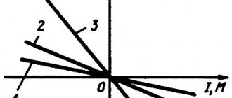
The battery operating time is estimated based on a certain calculated load using the discharge characteristics supplied as catalog or data sheets of the batteries (example in Fig. 2).
Rice. 2. Discharge characteristics of battery GroE
This characteristic is usually given for operating a new battery at 25 °C. Since operating conditions may be different, there is a need to recalculate the discharge characteristics taking into account the aging and operating temperature of the battery.
According to GOST 26881–86, the battery capacity at the end of its service life (operating time) must be at least 80% of the nominal.
The new version of the EnergyCS Electrics PC implements a powerful tool for automated battery selection. It allows you to automatically select the number of batteries of each type according to a given load time and permissible voltage at the end of the discharge. The calculations can take into account shock loads at the end of the discharge mode, including when using voltage stabilizers.
The program also provides a battery calculator mode (Fig. 3), which allows you to instantly calculate the battery operating time or current using discharge characteristics calculated using the Peukert equation taking into account the ambient temperature.
Rice. 3. Automated selection of batteries in the PC EnergyCS Electrics
In addition, the program allows you to perform a refined check of the selected battery, taking into account the current-voltage characteristics and the specific entered model, including taking into account the elemental switch.
Direct current saves alternating current
Just a few years after large-scale construction of power plants and alternating current networks began, it turned out that alternating current has problems transmitting energy... over long distances! Corona discharge in high-voltage overhead lines, which can account for up to half of the losses, surface effect, in which alternating current flows unevenly through the conductor and, because of this, requires conductors of larger diameter, reactive power due to the high capacitance of submarine cables, “eaten up” almost 100% alternating current after 50 km - all this caused losses of percent and tens of percent of power in the first main alternating current networks.
Leaks over long distances are the first thing. And secondly, interconnection of AC power grids required perfect synchronization of generators located in different parts of the country. In the absence of synchronization, the generator, at best, will not supply current to the network, at worst, a short circuit will occur.
The salvation of high-voltage alternating current networks was high-voltage direct current networks, free from some of the disadvantages of their competitors. Direct current does not create skin effect in the conductor and therefore uses the entire cross-sectional area of the conductor with maximum efficiency (this reduces the diameter and cost of the wires). There is no reactive power in DC circuits, so there is no loss in submarine cables with high capacitance.
In high-voltage AC networks, the thickness of the skin layer (marked with the letter δ) is determined by the point where the current density drops by 63%. In networks with a frequency of 50 Hz, the skin layer reaches 9.34 mm - part of the volume of an expensive conductor simply does not work. Source: biezl/Wikimedia Commons
A remarkable synergy emerged: power plants and consumers use alternating current, but DC networks are used to transport it hundreds of kilometers. There was only one “trivial” problem left - how to turn alternating current into direct current and vice versa?
At the end of the 19th century, Swiss engineer Rene Thury proposed using a “motor-generator” system to connect networks with different types of current, in which at one end of the network alternating current rotated a motor driving a direct current generator, and at the other end direct current rotated its the turn was rotated by a motor with an alternating current generator. An idea that was brilliant in its simplicity, but with low efficiency - double conversion due to motors and generators “ate up” part of the power. However, there were no other solutions other than the Thüry system, so in 1883 the construction of backbone DC networks with Thüry machines began, connecting large power plants and cities in Europe.
One of Türi's cars. The largest of them, weighing 4500 kg, generated 66 kW. Source: Wikimedia Commons
In 1902, American Peter Cooper-Hewitt invented the mercury-arc rectifier, a simple device for converting alternating current into direct current. The original Cooper-Hewitt rectifier was an intricate glass flask with electrodes coming out of it, the bottom of which was filled with mercury. The rectifier looks very impressive in operation. However, due to the fragility of the flask, the glass in the rectifier was soon replaced with metal.
The work of mercury arc rectifiers is fascinating. Alas, now you can only admire such beauty in museums - mercury rectifiers have not been used for a long time, and those that remain are made of metal.
Mercury rectifiers gave impetus to the development of high-voltage direct current networks - instead of bulky and unreliable Türi system machines, it was enough to install rectifiers, the only disadvantages of which were potential toxicity during depressurization and the need for good cooling due to thermal losses. The efficiency of the device reached 98-99%.
To replace mercury rectifiers, gastrons and thyratrons were created (1940s), MOSFET field-effect transistors and IGBT polar transistors with an insulated gate (1959), and GTO turn-off thyristors (1962) - more advanced, compact and reliable converters.
Modern thyristor AC/DC converter. Source Toshiba Energy Systems & Solutions Corporation
Battery Directory
The battery directory of the EnergyCS Electrics complex stores the minimum required set of data for carrying out all types of calculations. Discharge characteristics are presented in the form of a table, where only the lower limit points of the discharge are indicated. Temperature characteristics, battery discharge and aging coefficients are collected in a separate reference book. This data is stored in relative units separately from specific types of batteries, which makes it possible to apply them to an entire group of batteries.
During input, automatic conversion of units is provided, which makes it even faster and more convenient.
The general view of the directory is shown in Fig. 4.
Rice. 4. Directory of batteries and their characteristics of the EnergyCS Electrics software package
When calculating the operating time from a battery, the Peukert equation is used, which consists in the fact that the relationship between the discharge current I and the battery discharge time T (from fully charged to fully discharged) is a constant ratio and can be described by the formula
— Peukert capacity (constant ratio for a given battery), n — Peukert exponent.
When every percentage counts
Despite significant progress in the field of current rectification, equipment for converting alternating current into direct current and vice versa still costs a lot of money. So large that the construction of AC networks, even taking into account the increased consumption of material for wires, is much cheaper. Regardless of the length of the line, the starting price of a high-voltage DC line necessarily includes the cost of two converters at the beginning and end of the line - large and very expensive devices produced by only a few companies in the world, including Toshiba. This equipment accounts for up to half the cost of the network.
But as the length of the line increases, the cost of an AC line increases faster than that of a DC line. This is due to the complexity of the HVAC line - to transmit the same power to HVDC, you need half as many conductors of smaller diameter, which means half as many supports, which themselves cost a lot and require extremely expensive installation. With a line length of about 600 km, the cost of HVDC and HVAC is equal, but over long distances, about 2000 km, HVDC is much cheaper than HVAC, by about 30-40%, and this is hundreds of millions of dollars in savings.
HVDC and HVAC costs intersect on a line about 600 km long. Further, HVDC becomes noticeably more profitable. Source: wdwd/Wikimedia Commons
For every 1000 km of line, losses in HVDC are 2-3%, and the most modern equipment can reduce this parameter to 1%. HVAC losses can be as high as 6%. Even in the most efficient AC networks with the best equipment, losses will be 30-40% greater than in HVDC. A few percent of total power seems to be tolerable nonsense? When it comes to networks transmitting several gigawatts, each percent turns into dozens of wasted megawatts that could be used to power a small city. Not to mention lost profits.
What it is
The abbreviation stands for power lines. This installation is necessary for transmitting electrical energy through cables located in open areas (air) and installed using insulators and fittings to racks or supports. The linear inputs or linear outputs of the switchgear are taken as the starting and ending points of power lines, and for branching - a special support and a linear input.
What does a power line station look like?
Supports can be divided into:
Power lines can be divided into overhead and underground. The latter are increasingly gaining popularity due to ease of installation, high reliability and reduced voltage losses.
Note! These lines differ in the method of laying and design features. Each has its own pros and cons.
When working with power lines, you must follow all safety rules, because during installation you can not only get injured, but also die.
Types of supports used
What is the power line voltage
Based on certain characteristics, you can find out the voltage of power lines by their appearance. The first thing you should pay attention to is the insulator. The more of them there are on the installation, the more powerful it will be.
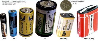
The most popular 0.4 kV overhead line insulators. They are usually made of durable glass. Based on their number, the power can be determined.
VL-6 and VL-10 are the same in shape, but much larger. In addition to pin fixation, sometimes such insulators are used similar to garlands based on one/two samples.
Note! On a 35kV overhead line, hanging insulators are most often installed, although sometimes you can see the pin type. The garland consists of three to five types.
The number of rollers in a garland can be as follows:
You can also find out the voltage by the number of cables:
In conclusion, it should be noted that in the modern world it is impossible to do without power lines. They supply the entire country with electricity. Currently, overhead and cable power lines are used everywhere.
Source