Reactive power sources are almost all electric motors, both large and small (for example, a fan in a computer unit). More complex reactive power source devices are nonlinear elements - for example, semiconductor devices (regulators, rectifiers, switching power supplies, etc.), which are widely used in modern consumer electrical installations.
In most consumer electrical installations, significant inductive reactive power is generated. This applies to industrial plants as well as office and residential load centers.
Reactive power not only wastes a portion of the energy produced by generators on the grid. With an increase in inductive power, the voltage on the buses of substations of electricity consumers decreases. A feature of modern semiconductor regulators is that as the voltage decreases, they begin to consume more current. Which in turn leads to an even greater increase in reactive power. This can lead to a cascading accident - the so-called voltage avalanche. When a decrease in voltage in the external network (for example, as a result of repairs or an accident) leads to an explosive increase in the reactive load of the consumer and to an emergency decrease in voltage in the network.
Therefore, reactive power compensation is not only a means of increasing the efficiency of equipment and the quality of electrical energy, but also a means of ensuring the reliability of power supply.
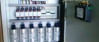
Since most electrical installations of consumers generate inductive power, it can be compensated using special capacitor units - banks of static capacitors (SCB). Electrically, the BSC is a capacitor whose power is approximately equal to the equivalent inductive power of the consumer's electrical installation. BSK compensates for the decrease in bus voltage and increases the power factor.
A battery of static capacitors (shunt capacitor bank) is an electrical installation consisting of capacitors, auxiliary electrical equipment and a busbar, designed to compensate for reactive power and increase voltage. BSK are installed in AC electrical networks with voltages of 0.4 – 500 kV.
BSK - general
The issue of efficient use of fuel and energy receives a lot of attention in many countries around the world.
In the strategic development plan of many countries, a separate aspect is allocated to the competent use of available energy. To achieve maximum effect, it is necessary to consider all stages: from the generation of electrical energy to its final use. The supply of electrical energy over many kilometers using power lines in any case leads to inevitable losses. In this case, there is an increase in the load of equipment that is designed to redistribute energy. Thus, there is a decrease in the reliability of the functioning of parts of energy networks. Free consultation with a BSC Engineer
Purpose and scope
BSK are used to increase the power factor in electrical networks. They allow reactive power to be produced at load nodes rather than at remote power stations, which reduces voltage and power losses in the power supply system. They are used in close proximity to large load nodes on the high voltage side. Individual and group reactive power compensation (RPC) is carried out by various devices at a voltage class of 0.4-6-10 kV; at high voltage, with the help of BSK, centralized RPC is usually carried out.
Voltage regulation using BSK
The voltage at different points in the power system varies depending on the load and network design.
According to GOST 13109-87, this parameter should be in the range from 5 to 20% (Table 1). Grid voltage
| Rated voltage (linear) UNOM, kV | 6 | 10 | 20 | 35 | 110 | 220 | 330 | 500 | 750 | 1 150 |
| Highest operating voltage (linear), kV | 7,2 | 12 | 24 | 40,5 | 126 | 242 | 363 | 525 | 787 | 1 200 |
| Excess of the highest operating voltage over the rated voltage, % | 20 | 20 | 20 | 15 | 15 | 10 | 10 | 5 | 5 | 5 |
In addition, the limitation on the highest operating voltage of electrical equipment is dictated by the reliability of the insulation of electrical equipment, since constantly increased voltage causes accelerated aging of the insulation and its failure. For most electricity consumers, long-term voltage deviations from the nominal voltage are allowed by no more than ±5%. Exceeding the rated voltage leads to a reduction in the service life of the equipment; a decrease reduces the productivity and efficiency of electrical receivers, the throughput of power lines, and can disrupt the stability of the operation of synchronous and asynchronous electric motors.
As can be seen from Table 1, with an increase in the rated voltage, the permissible voltage increases decrease from 20 to 5%. This is due to the rising cost of insulation in higher voltage installations, minimizing insulation costs and running equipment at near rated voltage.
Allowable voltage drops in the power system are also limited and range from 10 to 15%. As we can see, voltage fluctuations from -15 to +20% are possible in electrical networks. Therefore, when changing the circuit parameters, load size, and operating mode of the electrical network, it is necessary to regulate the voltage level through technical measures.
As you know, the consumer voltage is determined by the formula:
U = UCP − (PНRE + QНХЭ) / UN,
where: UCP is the voltage of the power center;
РН and QН - active and reactive power of the consumer load;
RE and XE - equivalent active and inductive resistance between the power center and the consumer.
From the above formula it is clear that it is possible to influence the voltage of the consumer by changing the reactive power QH, for example, by regulating it using a battery of static capacitors.
Problems solved by installing BSK
Using installations, it is possible to successfully solve a number of the following problems:
- Reduced energy losses;
- Voltage level equalization;
- Improving power quality;
- Reducing the use of reactive energy;
- Increasing the capacity of existing electrical networks without using the capacity of power plants;
- Maintaining the stability of the electrical supply system components.
| Modern production | Individual order | All batteries are in stock |
BATTERIES OF STATIC CAPACITORS BSK AND BLOCKS OF CAPACITORS TYPE BKE
Designed to complete shunt batteries with a voltage of 6; 10; 35; 110 and 220 kV frequency 50 Hz.
| Standard rating | Voltage, kV | Power, kvar | Capacity, µF | Overall dimensions (length x width x height), mm | Weight, kg |
| BKE1-1.05-252 U1 | 1,05 | 252 | 728 | 900 x 580 x 575 | 150 |
| BKE1-1.05-300 U1 | 300 | 866 | |||
| BKE1-2,1-400 U1 | 2,1 | 400 | 289 | ||
| BKE2-1.05-500 U1 | 1,05 | 500 | 1444 | 900 x 580 x 910 | 260 |
| BKE2-1.05-600 U1 | 600 | 1732 | |||
| BKE2-2.1-800 U1 | 2,1 | 800 | 578 |
Reducing losses during electricity transmission using BSK
The share of technological losses of electricity in distribution electrical networks with a voltage of 6-10 kV averages 8-12% of the amount of electricity supplied to the network of this voltage. The amount of electricity losses is determined by the parameters of the electrical circuit, the design of the networks and the load mode. As calculations for real 10 kV networks have shown, electricity losses significantly depend on the amount of reactive power transmitted to consumers through network elements. For example, when the power factor (tg φ) changes from 0.5 to 0.8, electricity losses increase by approximately 20%.
An analysis of the readings of active and reactive electricity meters showed that the power factor values on the 10 kV buses of power sources and at 35-110/10 kV substations change during operation and reach values of 0.77-0.85. That is, electricity losses during reactive power transmission become significant.
| Nomenclature of BSK and KRM | Power |
| KRM 0.4—0.66 kV | 50—2000 kvar |
| BSK 6-10 kV | 5—50 MVAr |
| BSK 35 kV | 10—50 MVAr |
| BSK 110 kV | 20—60 MVAr |
| BSK 220 kV | 52—104 MVAr |
An effective way to reduce electrical energy losses in 10 kV networks is to install banks of static capacitors.
The choice of power and installation locations of compensating devices is carried out according to the condition of minimum reduced costs, taking into account the cost of compensating devices and the expected savings from reducing electrical energy losses.
| Technical characteristics of BSK 104 MVAr 220 kV | |
| Power, MVAr | 104 |
| Voltage, kV | 220 |
| frequency Hz | 50 |
| Rated current, A | 272,9 |
| Capacity, µF | 6.84 (one capacitor 27.37) 0..+5% |
| Ambient temperature | from -50 to +50°С |
| Relative humidity, % | up to 90 |
| Altitude above sea level, m | up to 1000 |
| Protection | Fuses built into capacitors. Unbalanced current (TFZM-220) – 3 pcs. Current-limiting reactors – 3 pcs. |
| Number of racks | 3 |
| Weight, kg | 22 200 |
| Dimensions L × W × H, mm | 16 500 × 1 970 × 9 200 |
| Dimensions L × W × H, mm | 22,500 × 22,500 (along the fence) |
| Connection: - serial groups - parallel blocks - serial groups | 16 2 2 |
| Total capacitors | 192 |
| Neutral operating mode | Solidly grounded neutral |
| Design | Modular, star connection of capacitors with a solidly grounded neutral, two parallel groups of capacitors for each star phase, each group has 16 capacitors operating in series, 2 capacitors per group |
| Capacitors | Single phase 542 kVAr / 7.94 kV / 50 Hz with built-in fuses |
Fuses in BSK Batteries
| Battery with external fuse | Battery with internal fuses | Battery without fuses |
Design features of static capacitor banks
Currently, open-type BSKs are in high demand for use directly at outdoor switchgear. In this case, it is not necessary to erect a number of additional buildings. The devices produced by NPO PromElectroAvtomatika LLC fully meet the requirements of the relevant standards. They meet all technical requirements that apply to devices for resistance to the negative effects of climate. The complete set of units includes a capacitor of the KEPF type (with one phase). Fuses are placed inside it to help identify areas where a malfunction has occurred. In this case, the capacitor continues to function. This allows for uninterrupted operation of all devices over a long period of time. The capacitors are located directly in metal frames, which are made from special materials. They have an anti-corrosion coating that protects it from the negative effects of the environment. The capacitors are insulated based on the capabilities of the device housings. Electrical connections of capacitors are made with flexible wires with multiple cores and bus bars. Flexible conductors are connected using a die clamp, which was specially designed for this purpose. This avoids oxidation. It is also worth noting the use of a special electrically conductive lubricant, which ensures a minimum level of resistance.
All BSKs are connected to each other to signal the occurrence of an emergency and errors during their use. In the event of a mechanical impact on the capacitor section in the event of an emergency, the fuse located inside will blow. This leads to a transformation of the capacity of one of the existing battery arms. Subsequently, the unbalance current moves in the conductor, controlled by a special relay. It directly activates an alarm indicating the occurrence of an unusual situation in the operation of the device. The lowest current level of this type occurs when a capacitor placement plan is formed individually for each unit.
At the customer's request, capacitor blocks for high-voltage shunt batteries for other voltages and powers can be developed and manufactured with both vertical and horizontal arrangement of capacitors in the blocks. Batteries of static capacitors BSK for voltage 35; 110 and 220 kV are developed and manufactured according to individual customer requirements.
- 1193,6613,5
| № | Battery rating designation | Rated voltage, kV | Maximum permissible voltage, kV | Nominal capacity, µF | Rated power, MVAr |
| 1 | BSK-6-2.7 UHL1 | 6 | 7,2 | 238,73 | 2,7 |
| 2 | BSK-6-4 UHL1 | 353,68 | 4 | ||
| 3 | BSK-6-5.4 UHL1 | 477,46 | 5,4 | ||
| 4 | BSK-6-6 UHL1 | 530,52 | 6 | ||
| 5 | BSK-6-6.7 UHL1 | 592,41 | 6,7 | ||
| 6 | BSK-6-8 UHL1 | 707,36 | 8 | ||
| 7 | BSK-6-9.4 UHL1 | 831,14 | 9,4 | ||
| 8 | BSK-6-10 UHL1 | 884,19 | 10 | ||
| 9 | BSK-6-12 UHL1 | 1061,03 | 12 | ||
| 10 | BSK-6-13.5 UHL1 | ||||
| 11 | BSK-10-2.5 UHL1 | 10 | 12 | 79,58 | 2,5 |
| 12 | BSK-10-3.75 UHL1 | 119,37 | 3,75 | ||
| 13 | BSK-10-5 UHL1 | 159,15 | 5 | ||
| 14 | BSK-10-5.65 UHL1 | 179,85 | 5,65 | ||
| 15 | BSK-10-7.5 UHL1 | 238,73 | 7,5 | ||
| 16 | BSK-10-8.75 UHL1 | 278,52 | 8,75 | ||
| 17 | BSK-10-10 UHL1 | 318,31 | 10 | ||
| 18 | BSK-10-11.25 UHL1 | 358,10 | 11,3 | ||
| 19 | BSK-10-12.5 UHL1 | 366,06 | 11,5 | ||
| 20 | BSK-10-13.15 UHL1 | 418,58 | 13,2 | ||
| 21 | BSK-10-15 UHL1 | 10 | 12 | 477,46 | 15 |
| 22 | BSK-35-3.8 UHL1 | 35 | 40,5 | 9,87 | 3,8 |
| 23 | BSK-35-5.1 UHL1 | 13,25 | 5,1 | ||
| 24 | BSK-35-7.6 UHL1 | 19,75 | 7,6 | ||
| 25 | BSK-35-10.2 UHL1 | 26,50 | 10,2 | ||
| 26 | BSK-35-11.4 UHL1 | 29,62 | 11,4 | ||
| 27 | BSK-35-15.2 UHL1 | 39,50 | 15,2 | ||
| 28 | BSK-35-19 UHL1 | 49,37 | 19 | ||
| 29 | BSK-110-12.5 UHL1 | 110 | 126 | 3,29 | 12,5 |
| 30 | BSK-110-17 UHL1 | 4,47 | 17 | ||
| 31 | BSK-110-25 UHL1 | 6,58 | 25 | ||
| 32 | BSK-110-34 UHL1 | 8,94 | 34 | ||
| 33 | BSK-110-37.5 UHL1 | 9,86 | 37,5 | ||
| 34 | BSK-110-50 UHL1 | 13,15 | 50 | ||
| 35 | BSK-110-63 UHL1 | 16,57 | 63 | ||
| 36 | BSK-110-67 UHL1 | 17,63 | 67 | ||
| 37 | BSK-110-75 UHL1 | 19,73 | 75 | ||
| 38 | BSK-110-84 UHL1 | 22,10 | 84 | ||
| 39 | BSK-110-91 UHL1 | 23,94 | 91 | ||
| 40 | BSK-110-100 UHL1 | 26,31 | 100 | ||
| 41 | BSK-110-113 UHL1 | 29,73 | 113 | ||
| 42 | BSK-110-125 UHL1 | 32,88 | 125 | ||
| 43 | BSK-110-134 UHL1 | 35,25 | 134 | ||
| 44 | BSK-110-143 UHL1 | 37,62 | 143 | ||
| 45 | BSK-110-156 UHL1 | 41,04 | 156 | ||
| 46 | BSK-220-25 UHL1 | 220 | 252 | 1,64 | 25 |
| 47 | BSK-220-33.5 UHL1 | 2,20 | 33,5 | ||
| 48 | BSK-220-50 UHL1 | 3,29 | 50 | ||
| 49 | BSK-220-67 UHL1 | 4,41 | 67 | ||
| 50 | BSK-220-75 UHL1 | 4,93 | 75 | ||
| 51 | BSK-220-100 UHL1 | 6,58 | 100 | ||
| 52 | BSK-220-125 UHL1 | 8,22 | 125 | ||
| 53 | BSK-220-134 UHL1 | 8,81 | 134 | ||
| 54 | BSK-220-150 UHL1 | 9,86 | 150 |
Structure and characteristics of capacitor banks
Several capacitors are required for manufacturing. They are connected in series. These radio parts are produced in different capacities and for different voltages.
What is a capacitor bank? These are essentially capacitors connected one after another. Their connection can be serial, parallel or mixed.
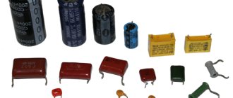
What is a capacitor?
Essentially, this is a part consisting of two conductive plates, divided in half by a dielectric. This device stores energy and releases it. Moreover, the process happens very quickly. If you charge a 1000 microfarad capacitor with a voltage of 25 volts and connect an LED to it. It will burn out in only 5-10 seconds.
It was experimentally found that at the moment of charging an electric field appears around the conductors. The increase in charge occurs due to high capacity and increased voltage. The capacitance increases as a result of an increase in the size of the conductors that make up the capacitor. It will also be large if the conductors are located very close to each other.
There is insulating material between the conductors. Its role is usually played by paper, film or simply air. All this electricity practically does not conduct. The dielectric should be carefully selected, since at high currents it must provide reliable insulation. Even if it is only 10-15 microns thick.
The quality of an insulator depends on its permeability, or ability to store charge. For example, the permeability of paper is 3.54, and that of film is 2.5-2.7.
"H-type" circuit
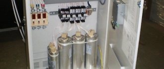
Naturally, the batteries are supplied based on the needs of the customer. The devices consist of a frame made of special types of metals in which capacitors are placed. To protect the capacitors, they are galvanized. Also in the device body there are various types of insulators, bus bars, devices for measuring current, units to enhance the protection of the device, reactors that limit the current and a set of accessories. The company's products can be supplied either assembled or disassembled. The final collection is carried out under the control of the head of the enterprise’s engineering service. Many years of successful battery production can greatly simplify installation, reducing time and material costs for installing the device. Thus, the company’s products are distinguished by their quality and reasonable cost.
Design
BSK consists of groups of power capacitors assembled into steel supporting blocks mounted on polymer insulators. The BSC is performed on three racks with capacitors, current-limiting reactors and current transformers placed on them. Between the BSK racks there are 6-meter passages for a truck crane, intended for the installation of capacitor units.
BSK is supplied in the U1 version for temperatures from -55 to +45°C. For lower temperatures, the BSK is installed in an insulated prefabricated building. Steel structures are made of welded profiles, protected from corrosion by galvanic zinc plating (zinc coating - at least 650 g/m2). The structures are assembled into blocks of 6-8 capacitors, mounted on site and complete with fasteners, lugs and copper bars for connecting capacitors, as well as flexible copper transitions. BSK uses power capacitors 700 kVAr / 6-10 kV, 560 kVAr / 11.7 kV for voltages 35 kV, 542 kVAr / 7.94 kV for voltages 110-220 kV with two porcelain insulators and built-in fuses.
TFZM current transformers (1 per phase) are connected by the primary winding in the gap of two parallel groups, and in case of imbalance they issue a signal to the relay protection and automation devices to turn off the main switch. Current-limiting reactors (1 per phase) limit the current when the BSC is turned on. The connections are made with a flexible copper busbar to prevent damage to the insulators during thermal expansion/compression or when exposed to electrodynamic forces.
When ordering a BSC, indicate the battery power, rated voltage and short-circuit current at the installation site, the type and number of capacitors in the battery, placement category and climatic modification.
Victor ITKIN, technical director of JSC Matic-Electro.
Distinctive features of BSK LLC NPO PromElektroAvtomatika
All products of the enterprise undergo mandatory certification. They have an adequate price, which quickly pays for itself. Thanks to many years of operation, devices produced by NPO PromElectroAvtomatika LLC are reliable and will serve for many years. The devices are developed based on individual customer requirements, which allows us to take into account all the nuances. The implementation of numerous projects that are being implemented in many countries around the world confirms the success of the work of NPO PromElectroAvtomatika LLC. Much attention in the work of the enterprise is paid to quality control. All products undergo mandatory testing, which confirms their potential for further use and application. If you are interested in BSK, then you can contact us at the indicated telephone numbers. You will be able to ask questions that interest you regarding our products. Below is a product catalog where you can download. Here are presented various types of BSK, from which you can select the device models that interest you.
BSK-35-15 BSK-6.3-9.2 BSK-12.64-7.2 BSK-103-30 BSK-103-30

