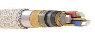
Magnetic field amplifier
The electromagnetic field is inextricably linked with current. Its properties are used in all electrical machines, electronics and automation devices. The purpose of magnetic cores is to transmit and amplify the magnetic field.
A magnetic field amplifier is a core surrounded by turns of coils (windings). Depending on the type of material used, certain characteristics of the MP are achieved.
There are two types of amplifiers based on their operating principle:
- amplistates – UMPs of static design;
- Transducers are a device with moving elements.
Why is a magnetic circuit needed?
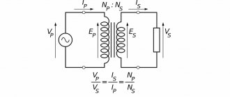
To understand what a magnetic circuit is, we need to consider the structure of a simple transformer. Two induction coils are wound on cores combined into a single structure. They are the magnetic circuits (MC).
What is the source of the magnetic field
The energized primary coil induces a magnetic field into the core, which induces magnetic flux into the secondary winding. As a result, the MF induces a current in the second coil, but with different characteristics.
Important! The cores are made of special transformer steel - ferrites. It is an alloy of iron with oxides of other metals.
Connection diagrams for windings of three-phase transformers
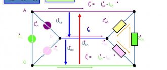
In most cases, the windings of three-phase transformers are connected either in star (Y) or delta (Δ).
The choice of winding connection diagram depends on a number of reasons. For example, for networks with a voltage of 35 kV and more, it is more profitable to connect the transformer winding in a star and ground the zero point, since in this case the voltage of the transformer terminals and transmission line wires relative to the ground will always be √ 3 times less than linear, which leads to a reduction in the cost of insulation. Incandescent lighting lamps of lower voltage have greater luminous efficiency, and it is advantageous to build lighting networks at a higher voltage. Therefore, the secondary windings of transformers supplying lighting networks are usually connected in a star and the lighting lamps are switched on to phase voltage - between the linear and neutral conductors. In a number of cases, when the winding current is small, when connected in a star, the windings are cheaper, since the number of turns is reduced by √3 times, and the cross-section of the wires also increases by √3 times, as a result of which the labor intensity of manufacturing the winding and the cost of the winding wire are reduced . On the other hand, from the point of view of the influence of higher harmonics and the behavior of the transformer under asymmetrical loads, it is advisable to connect one of the transformer windings in a triangle.
| Figure 1. Zigzag connection of three-phase winding |
In some cases, a zigzag connection of windings is also used (Figure 1), when the winding phase is divided into two parts, which are located on different rods and connected in series. In this case, the second half of the winding is connected counter to the first (Figure 1, a), since in this case the electromotive force (emf) of the phase will be √3 times greater (Figure 1, b) than with consonant switching on (Figure 1, c). However, when the halves of the winding are turned on oppositely, its e. d.s. (√3 E1) will still be 2 / √3 = 1.15 times less than when both halves are located on one rod (2 E1). Therefore, the consumption of winding wire when connecting with a zigzag increases by 15%. As a result, a zigzag connection is used only in special cases when uneven phase loading with the presence of zero-sequence currents is possible.
Tank with fittings
The transformer tank serves many functions. This is, firstly, a mechanical base, on which all elements of the transformer are attached inside and outside; it is also a cooling element that transfers heat losses to the surrounding air, and an oil reservoir that has sufficient oil density. Previously, corrugated and tubular tanks were produced. Now all the tanks are smooth, oval or rectangular in shape. The tank consists of a shell 3, a bottom 4, a frame 2 and a cover 1 (see Fig. 17) with holes for bolting to the frame.
Rice. 17 — Main parts of the transformer tank
The lid covers the tank and at the same time serves as the basis for installing the expander, inputs, drives of switching devices, lifting rings and other devices (see Fig. 18). The joint between the lid and the tank is connected with sealing rubber, placed on the frame in the ledge between the protruding end of the shell and the holes in the frame. To move the transformers, rollers are installed under the bottom; to lift the transformer, hooks are installed on the walls of the tank; for mounting radiators and filters - pipes with flanges; There are valves for filling transformers with oil.
1 - flange for connection to the expander, 2 - eye, 3 - HV input, 4 - switch, 5 - tap, 6 - thermometer, 7 - blow-out fuse, 8 - LV neutral input, 9 - LV linear input, 10 - cover, 11—installation location of the expander
Rice. 18 — Transformer cover (top view)
The expander serves to localize (compensate) fluctuations in the oil level in the transformer when the temperature changes (see Fig. 19). In addition, it reduces the area of contact between air and oil, and therefore protects the oil from premature oxidation. The volume of the expander is selected in such a way that during all operating modes of the transformer from the switched-off state to the rated load and when the ambient temperature fluctuates from – 45C to + 45C, there is oil in it (usually 8-10% of the volume of oil in the transformer). Figure 19 shows that when heated, oil from the transformer tank is forced out into the expander through the pipe connecting it to pipe 7; when the temperature drops, it flows back into the tank. An oil indicator 1 is installed on the end wall of the expander housing 2, on which there are 3 divisions with control numbers: -45, +15, +45. This means that when the transformer is not operating, the oil levels marked with divisions must correspond to the specified ambient temperatures. To collect and remove sediment and moisture from the bottom of the conservator, a sump 10 is provided with a hole that is closed with a plug 9 and also serves to drain oil from the conservator. The change in the oil level in the conservator, and therefore its volume, is compensated by atmospheric air entering the conservator from the environment through a dryer connected to pipe 6. The hole with plug 5 is intended for filling the conservator with oil, rings 3 are for lifting, pipe 4 is for connection to the safety pipe. To prevent precipitation from entering the transformer from the bottom of the expander, the end of pipe 7 protrudes inside the expander by 50-60 mm. The expander is installed slightly above the level of the cover 8 of the transformer tank using support plates 12, which are welded to brackets 11, bolted to the cover.
Rice. 19 — Expander device
The thermosiphon filter (Fig. 20) serves for continuous oil regeneration during the operation of the transformer and is a metal vessel 4 filled with silica gel 3 and connected by pipes 6 and 7 to the upper and lower pipes of the tank. Silica gel is loaded into it through hopper 5, and the spent gel is poured out through hopper 1. Metal gratings with meshes are installed in the hoppers to prevent silica gel from entering the transformer tank. Oil circulation through the filter is based on convection due to the temperature difference between the upper and lower layers of oil. Moistening and the need to replace the sorbent or restore it are indicated by a change in color from blue to pink indicator silica gel poured into the transparent cap of the air dryer. In modern transformers, the air dryer is built into the expander.
Rice. 20 — Thermosyphon filter
When transformers operate, the heat generated by the magnetic system, windings and other parts subject to heating is transferred to the oil. The oil transfers heat by convection to the walls of the tank, and the walls to the surrounding air. Each square meter of tank surface with natural oil circulation is capable of discharging 400-450 W. If the thermal load on the surface of the tank is greater, the temperature of the active part and the transformer may exceed the permissible temperature. In low-power transformers (25-40 kVA), energy losses are relatively small; a smooth surface of the tank is sufficient for its removal. In transformers with a power of more than 40 kVA, mounted radiators with oval and round pipes are used (see Fig. 21). They are bolted to the tank pipes, sealed with rubber gaskets. Radiators can be removable or welded. Removable radiators are easier to repair, but vibration in their seals often causes oil leaks.
1 - pipe with flange, 2 - box (manifold), 3 - oval pipe, A - distance between the centers of the pipes (main mounting dimension of radiators)
Rice. 21 — Straight-tube double-row radiator
Characteristics and principle of operation
The principle of operation of the MF is to increase the magnetic field directed to the secondary winding of the electrical device. The characterizing values of MF directly depend on the composition of the alloy used for the manufacture of cores. Ferromagnets are considered the most effective amplifiers.
Electromagnet
In order for the magnetic flux strength in the core to constantly increase, it is necessary to increase the current strength and the number of turns in the coil.
You should understand! The magnitude of the magnetic field is limited by the characteristics of the material from which the core is made.
To clearly express the characteristics of the magnetic circuit, they are displayed graphically on coordinate axes. The change in values looks like a closed curved line called a hysteresis loop.
Design
The transformer design assumes the presence of one or more individual coils (tape or wire), located under a single magnetic flux, wound on a core made of a ferromagnet.
The most important structural parts are as follows:
In devices you can most often see two types of winding: the primary, which receives electric current from an external power source, and the secondary, from which the voltage is removed.
The core provides improved return contact of the windings and has reduced magnetic flux resistance.
Some types of devices operating at ultrahigh and high frequencies are produced without a core.
The production of devices is established in three basic winding concepts:
The design of core transformers involves winding the winding onto the core strictly horizontally. In armor-type devices it is enclosed in a magnetic circuit and placed horizontally or vertically.
Reliability, operational features, design and principle of operation of the transformer are taken without any influence from the principle of its manufacture.
Hysteresis loop
Hysteresis in Greek means delay. The graphical representation of the hysteresis loop reflects the degree of magnetization of a body located in an external magnetic field. Hysteresis is the dependence of magnetization vectors and magnetic field strength in any medium on the applied external MF. The state of the body at a given time is compared with its previous state. In this case, there is a lag in the body’s reaction to the influence of external MF. The physical effect is clearly manifested in ferromagnets: iron, cobalt, nickel and their alloys. The hysteresis loop provides an explanation for the existence of permanent magnets.
Hysteresis loop
Note! Magnetic hysteresis of a ferromagnet is the lag between changes in the degree of magnetization of a body and changes in the external magnetic field. That is, the loop shows the dependence of the degree of magnetization on the sample’s history
The magnetic permeability of a ferromagnet is a variable value; it is closely related to the induction of an external field. The magnetization curve of the core is a curved loop, at a certain degree of saturation of the ferromagnetic field. In the future, this value does not increase. If the external induction is reduced to zero, the ferromagnet will retain residual magnetization. When the direction of the external field changes, the ferromagnet is remagnetized in the opposite direction.
Types of magnetic cores
Magnetic cores are made of rod, armor and ring structures.
Rod type
Vertical cores of stepped cross-section form a circle with horizontal yokes. The windings are located only on the vertical elements. The entire magnetic circuit system is arranged in the form of a closed circuit.
Lamellar magnetic cores
Armor type
The cores have a rectangular cross-section. They occupy a horizontal position. The windings are also made in a rectangular shape. In order to implement such an equipment configuration, a rather complex production technology is required. Therefore, this type of MP is used only in special types of transformers.
Ring – toroidal type
Ring tape magnetic cores are used in the assembly of single-phase power transformers. MPs are made from cold-rolled electrical steel with a thickness of 0.08, 0.3 and 0.35 mm. Toroidal cores are made of ferrite or carbonyl iron. They are widely used in radio electronics.
Ring toroidal MPs
Lamellar (laminated) magnetic circuit
The magnetic core of an electrical product (device), according to GOST 18311-80, is the magnetic system of an electrical product (device) or a combination of several of its parts in the form of a separate structural unit.
A plate magnetic circuit is a part or set of parts designed to pass the main part of the magnetic flux excited by an electric electric shock The magnetic core is an integral part of transformers, inductors, relays, etc.
Stages of production of lamellar magnetic cores, features of assembly of lamellar magnetic cores
In their design and properties, lamellar (laminated) magnetic cores differ significantly from twisted tape and ring (toroidal) magnetic cores. The production of cores of this type is regulated by GOST 20249-80 and is carried out according to the following scheme:
- Cutting materials. Produced on slitting units equipped with circular knives. The material is cut into strips of the required sizes.
- Cutting plates. Parts are cut using guillotines and cross-cutting units (including punching holes in the plates).
- Assembly of magnetic circuits. It is produced using the technology of assembling butt or laminated magnetic cores.
- Quality control. Measuring the main characteristics of the resulting products and their compliance with the technical specifications
The procedure consists of a set of plates in a package and their fastening (pulling) together. The parts are connected in several ways:
- studs and bolts;
- crimping staples;
- metal holder.
An important assembly condition is the isolation of fasteners from the magnetic circuit. In some cases, the package is compressed. In this case, a change in magnetic permeability and electrical resistance occurs. The procedure is performed at a pressure of 2-5 MPa, the compression force is selected depending on the materials and design of the plates.
After compression, quality control must be carried out. With its help, it is possible to find out the resulting magnetic induction and permeability, as well as the no-load current of the plate magnetic circuit.
Compliance with a precise technological process allows us to obtain reliable and durable structures that can withstand heavy loads and are ready for use in almost any conditions.
Magnetic cores of transformers
The magnetic core of a power transformer consists of steel plates. Using laminations instead of a solid core reduces eddy currents, which increases efficiency and reduces heat.
magnetic cores of transformers
Magnetic cores of type 1, 2 or 3 are produced by stamping. Magnetic cores of types 4, 5 or 6 are produced by winding a steel tape onto a template, and magnetic cores of types 4 and 5 are then cut in half.
The types of magnetic cores of transformers are:
1, 4 – armored, 2, 5 – rod, 6, 7 – ring.
True, I have never seen stamped ring magnetic cores. To determine the cross-section of the magnetic circuit, you need to multiply the dimensions “A” and “B”. For calculations in this article, the section size in centimeters is used.
Transformers with stamped armored magnetic cores, position 1, and core magnetic cores, position 2. Transformers with twisted rod position 1 and armored magnetic cores position 2. Transformers with twisted ring magnetic cores.
Butt design
In this design, the assembly of yokes and rods is carried out separately. First, a winding is mounted on the rod, after which the upper yoke is attached. To insulate the plates, electrical cardboard is placed between the joining elements. After installing the yoke, the structure is pressed and tightened using vertical pins. This type of assembly is used for shunt and current-limiting reactors. This depends mainly on the dimensions of the installation. With small dimensions of the final product, this assembly is very convenient, since you only need to remove the upper yoke to install the windings.
When it comes to using such a design in power transformers, there is a need for bulky devices to tie the product. The surfaces of the rods and yokes to be joined must be mechanically processed. This reduces magnetic resistance, but requires large material costs and time. Therefore, another type of assembly is used for power transformers - fusion.
Laminated design
In this design, the yokes and rods form a binding. They are divided into layers of a certain thickness. Each package consists of two or three sheets of steel. Each layer contains plates, some of which must fit into the yoke. It is necessary to ensure that the plates of the previous layer overlap the joints of the plates of the adjacent element.
The advantages of this type of assembly are:
Among the disadvantages, one can highlight the factor of more complex assembly of the transformer.
First, it is necessary to strip the upper yoke into separate layers. Then the windings are placed on the rods and the fusion is repeated. This makes installation more labor-intensive. It must be carried out by a qualified specialist, since poor-quality assembly can worsen the technical parameters of the transformer.
Design of magnetic cores of power transformers
Armored magnetic cores have rectangular cross-sections, and rod and armored magnetic cores have the cross-sectional shape of a polygon inscribed in a circle (Figure 8, a, b). In this case, the windings have the form of circular cylinders and, due to the stepped cross-section of the magnetic circuit, the coefficient of filling the winding cavity with steel is large. This design is the most rational from the point of view of material consumption, reducing the size and cost of manufacturing the transformer, as well as the mechanical strength of the windings. The number of magnetic circuit stages increases with increasing power. In powerful transformers, channels are provided in the cross-section of the magnetic core for cooling it with circulating transformer oil (Figure 8, b).
Fig. 8, Sectional shapes of transformer rods, Fig. 9 Sectional shapes of transformer yokes
To simplify the manufacturing technology of yokes, their cross-section is taken rectangular or with a small number of steps (Figure 9). The cross-sectional shape of the yoke and its connection with the rod are selected to ensure uniform distribution of the magnetic flux in the cross-section of the magnetic core. The cross-sectional areas of the yokes are selected so that the induction in them is 10–15% less than in the rods. The tie rods of medium (up to 800 - 1000 kVA × A) and high power transformers are shown in Figures 10 and 11. The transformer yokes are tied using wooden or steel beams. For very powerful transformers, more complex magnetic circuit designs are also used.
Fig. 10. Tie rods of medium power transformers. Figure 11. Tie rods of high power transformers 1 – wooden plank; 2 – insulating cylinder; 3 – wooden rod 1 – steel pin; 2 – tube made of baked paper; 3 and 5 – washers made of electrical cardboard; 4 – steel washer
are compressed (fastened) to avoid fluffing This is usually done by placing a bandage made of glass tape or steel wire on the rod. The steel bandage is made with an insulating buckle, which eliminates the creation of closed steel turns on the rods. The bandage is applied evenly, with a certain tension. To crimp yokes 3 and their joints with rods 1, yoke beams 2 are used, which are tightened with pins in places extending beyond the outer rods (Fig. 18). In order to avoid the occurrence of a potential difference between the metal parts during operation of the transformer, which can cause breakdown of the insulating gaps separating these parts, the magnetic circuit and its fastening parts must be grounded. Grounding is carried out with copper strips inserted between the steel plates of the magnetic circuit at one end and attached to the yoke beams at the other ends. Magnetic cores of low-power transformers (usually with a power of no more than 1 kVA) are most often made from a narrow strip of electrical cold-rolled steel by winding. Such magnetic cores are made split (Fig. 1.9), and after fitting the windings they are assembled end-to-end and tightened with special clamps.
Figure 12. Magnetic core of a low-power transformer Figure 13. Cutting sheets (a) and laying the magnetic core (b) of a low-power transformer
In single-phase transformers of very low power (up to 150 - 200 VA), an armored design of magnetic cores is used. At the same time, they strive to simplify their production and assembly as much as possible, as well as to reduce sheet steel waste. Typically, stamping of magnetic circuit sheets is carried out according to one of the options shown in Figures 12 and 13. In the first case, the sheet is cut out with one blow of the stamp and has a slot n; during assembly, the middle petal is temporarily bent and inserted inside the winding coil, the petal of the subsequent sheet is inserted into the coil from the opposite, end end, and so on. In the second case, W-shaped sheets Sh1 and Sh2 and yoke sheets Y1 and Y2 are simultaneously cut down (Figure 13, a), from which two layers of magnetic circuit sheets are made (Figure 13, b). In this case, the sheets are also inserted into the coil alternately from one and the other end.
Magnetic cores of power transformers are assembled from sheets of electrical steel 0.35 or 0.5 mm thick, grades 1511, 1512, 1513 or 3411, 3412, 3413. The use of cold-rolled steel has been increasingly expanding in recent years.
Intersheet insulation is carried out by one-sided gluing of steel sheets with insulating paper 0.03 mm thick or double-sided coating with insulating oil varnish.
Induction in the rods of transformers with a power of 5 kVA and above is in the range of 1.2 - 1.45 T for hot-rolled steels and 1.5 - 1.7 T for cold-rolled steels for oil transformers and, accordingly, 1.0 - 1.2 T and 1.1 - 1.5 T for dry transformers.
BUTT AND LAMINED MAGNETIC CONDUCTORS
Magnetic cores of power transformers are assembled from separate plates. The simplest design solution for the magnetic core and the subsequent first assembly of the transformer, i.e., fitting the windings onto the rods, would be a separate assembly of rods and yokes that make up the magnetic core. The diagram of the butt magnetic circuit arrangement is shown in Fig. 11.6, a.
However, the butt design suffers from a number of serious disadvantages. To avoid shorting the plates of the rod and yoke at the junction (Fig. 11.7, a), it is necessary to lay a gasket of insulating material
terial (Fig. 11.7, b).
But this gasket increases the magnetic resistance of the magnetic circuit, which leads to an increase in the magnetizing current. If the insulating gasket is damaged, the short circuit of the rod and yoke plates can lead to a so-called steel fire, i.e., a transformer failure.
Rice. 11.6. Design of magnetic cores:
a - butt; b - blended
Rice. 11.7. Butt connection between yoke and rod:
I - without insulating gasket; b - with an insulating gasket: 1 - yoke plate; 2—plate insulation; 3—insulating gasket at the joint between the yoke and the rod; 4 - path of eddy current closure; 5— rod plates
Due to these disadvantages, the butt design has not found widespread use. In the domestic transformer industry, a laminated design of magnetic cores has been adopted for power transformers of all capacities. It provides greater rigidity of the magnetic circuit, requires fewer fasteners and is more reliable in operation.
All even layers have the position of the plates, and all have the opposite (mirror) position, so that the plates of one layer overlap the joints in adjacent layers.
Thus, the plates of adjacent layers are, as it were, intertwined with each other (Fig. 11.6, b).
The magnetic core of a laminated structure is assembled from separate layers, each of which consists of several plates arranged in a certain way.
CHARGING DIAGRAMS FOR SINGLE- AND THREE-PHASE MAGNETIC CONDUCTORS
A diagram of the mixing of single- and three-phase core magnetic cores is shown in Fig. 11.8 and 11.9.
When laminating the magnetic circuit, the yokes and rods form as if one whole. But to attach the windings to the rods, i.e., for the first assembly of the transformer, after manufacturing the magnetic circuit, it is necessary to unload the upper yoke, i.e., remove all the sheets of the yoke, and after installing the windings, it is necessary to laminate it again.
To reduce unnecessary operations for double lamination of the upper yoke for size I transformers at some plants
Rice. 11.8. Charging diagram of a single-phase core magnetic circuit:
a is the first position of the plates (odd layers); b - second, opposite to the first, position of the plates (even layers); c - overlap of joints
Rice. 11.9. Charging diagram of a three-phase magnetic circuit: a - first position of the plates (odd layers); b—second, opposite to the first, position of the plates (even layers)
began to combine the operations of assembling the laminated magnetic core and the first assembly into one operation, in which the fusion of the magnetic core is carried out directly in the windings laid horizontally (Fig. 11.10).
Rice. 11.10 Assembly (lamping) of the magnetic circuit directly in the windings
In addition, in some factories, the fusion of the upper yoke in small transformers is also not done when assembling the magnetic circuit, and to lift it, the yoke beams are placed on rods below the future fusion.
Date added: 2019-02-12; ; We will help you write your work!
Source
Application of transformers
When transmitting electricity over long distances, quite large losses can occur due to heating of the wires. To avoid such a negative phenomenon, transformers are repeatedly used. Initially, the voltage at the power plant is increased accordingly with a significant decrease in current. After the energy passes through the power lines, before delivering the current to the consumer, the voltage is reduced to an acceptable level (220 V) using transformers.
Since three-phase current flows in power line networks, groups of 3 single-phase transformers connected in a star or triangular circuit are used to transform it. Three-phase transformers with a single magnetic core are also used. The equipment has high efficiency. Due to this, a large amount of heat is released. Therefore, powerful transformers are placed in containers filled with special oil.
Powerful power transformer
Various electrical appliances require power supply at a certain voltage level. To do this, transformers with the required characteristics are built into their housings. High-frequency pulse transformers are used to power modern radio engineering and electronic devices.
Transformers are the basis of control and measuring devices. The point of using such devices is to safely transmit the shape of the voltage pulses of the electrical circuit under study. For example, instrument transformers are used in diesel generator systems with medium power currents (up to 1 megawatt).
Matching transformers are used when connecting devices with low resistance to electronic stages with high input or output resistance values. An example would be connecting an audio amplifier to speakers that have very low impedance.
Additional Information. The amount of energy losses in a transformer directly depends on the quality of the electrical steel core. Minimal losses due to heating, hysteresis and eddy currents occur where the cores are assembled from a large number of sections.
Transformer bushings
The inputs are used to connect the transformer to the network. The inputs are installed in holes on the lid or, less commonly, on the side wall of the tank. There are different designs of inputs, they depend on the electrical parameters (voltage class and current value), the type of installation (internal or external) and on the method of connection to the transformer windings. The current-carrying rod or wire is insulated from the cover with porcelain insulators. Porcelain and metal lids have different volumetric expansion with temperature fluctuations and therefore a rigid fastening between them cannot provide the necessary oil tightness. Previously, they used a connection between insulators and metal parts through a special reinforcing putty. Figure 14 shows the HV input. The insulator is reinforced into a round flange. LV bushings are designed for high currents of the order of hundreds and thousands of amperes, and in order to avoid heating the flanges by eddy currents arising in them, all three insulators of LV bushings (Figure 15) are reinforced into a cage, which is secured in the common hole of the cover with studs and nuts on the seal.
1 - porcelain insulator; 2 - current-carrying pin: 3 - rubber washer: 4 - cap; 5 - flange; b - gasket; 7 — electric cardboard washer; 8— steel washer; 9— transformer cover; 10 - reinforcing putty
Rice. 14 — Reinforced VN input
Rice. 15 — Installation of LV bushings in the cage
Now all transformer factories have switched to the production of removable bushings, which are more technologically advanced to repair: replacing a damaged porcelain insulator does not require disassembling the transformer and disconnecting the taps inside the tank. The insulator (Figure 16) of the HV input is attached to the cover through cams made of aluminum alloy. They are fixed in a strict position by a steel flange.
1 — contact tip; 2 - bolt with nuts and washers; 3 — tip bolt; 4 - special nut; 5 — brass bushing; 6 - rubber ring; 7 — brass cap; 8 — screw for air release; 9 — rubber washer; 10 — stud protrusion: 11 — electric cardboard washer; 12 — stud collar; 13 - porcelain insulator; 14 - current-carrying pin; 15 — installation pin; 16 - nut; 17 - flange; 18 - cam; 19 — rubber gasket; 20 — transformer cover; 21 — getinaks bushing; 22—copper washer; 23 - nut
Rice. 16 — Removable HV input
The holes in the cover for LV inputs are connected by a slot welded with non-magnetic metal.
How are magnetic circuits arranged?
A magnetic circuit, in fact, is not as difficult to imagine as it might seem to a person who hears about them for the first time. Usually . Perhaps one of the simplest single-source examples to use is illustrated below:
Before continuing, let us agree that among electrical engineers the core is called a magnetic circuit . The part of the magnetic circuit on which there are no windings and which serves to close the magnetic circuit is called the “yoke”.
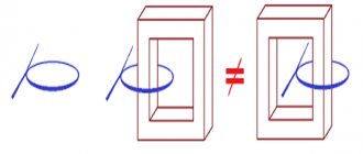
Let's start with the toroidal core. Such a toroidal core can serve as a form for a coil, no matter how strange it may sound. But what kind of coil? Well, the first thing that comes to mind is a wire that forms turns. Okay, but what is its purpose? Let's return to electrical circuits and remember that there are current / voltage sources, the so-called. So, in magnetic circuits
Let us now remember about ferromagnetic materials. Why them? The fact is that due to the high value of magnetic permeability, which indicates good magnetization of the ferromagnet, the magnetic field lines practically do not extend beyond the core, or do not extend at all. However, this will only be true when our core is closed or has small gaps . That is, ferromagnets have strongly pronounced magnetic properties, when, like paramagnets and diamagnets, they are much weaker, which can be observed in the following graph of the dependence of magnetization on the magnetic field strength:
Why are magnetic circuits laminated?
When laminating the magnetic circuit, the plates of the rod and yoke are overlapped, the air gap at the junction of the rods and the yoke can be minimal, which will reduce the magnetic resistance and reduce losses. The mechanical strength of a laminated magnetic core is much higher than that of a butted one.
Eddy currents create their own magnetic flux, which, in accordance with Lenz's rule, tends to weaken the change in the main flux. Therefore, they act in a demagnetizing manner, reducing the main flux.
Eddy current losses can be determined using the concept of active AC power.
In accordance with the Joule-Lenz law, eddy currents heat the conductors in which they arise. Therefore, eddy currents lead to energy losses (eddy current losses) in magnetic circuits (in the cores of transformers and AC coils, in the magnetic circuits of machines).
To reduce energy losses due to eddy currents (and harmful heating of magnetic circuits) and reduce the effect of “displacement” of magnetic flux from ferromagnets, the magnetic circuits of machines and alternating current devices are made not from a solid piece of ferromagnetic material (electrical steel), but from separate plates isolated from each other ( for example, special varnish). This division into plates located perpendicular to the direction of the eddy currents limits the possible contours of the eddy current paths, which greatly reduces the magnitude of these currents.
Date added: 2015-04-18; ; Copyright infringement
Source
Special types of transformers
This group includes:
Isolation transformers
Placing two windings of exactly the same design on a common magnetic circuit allows us to obtain the same output voltage from 220 volts 50 hertz at the input.
This begs the question: why make such a transformation? The answer is simple: to ensure electrical safety.
When the insulating layer of the wire of the primary circuit breaks down, a dangerous potential appears on the body of the device, which, through a randomly formed circuit through the ground, can shock a person and cause him electrical injury.
Galvanic separation of the circuit allows optimal use of power to electrical equipment and at the same time eliminates injury from breakdowns of insulation of the secondary circuit on the housing.
Therefore, isolation transformers are widely used where working with power tools requires additional safety measures. They are also widely used in medical equipment that allows direct contact with the human body.
High frequency transformers
They differ from conventional ones in the material of the magnetic core, which, unlike conventional transformer iron, is capable of transmitting high-frequency signals well, without distortion.
Used in electrothermal applications, in particular for induction heating in electrothermal installations for high-frequency metal welding, melting, soldering, hardening, etc.
Matching transformers
The main purpose is to match the resistances of different parts in electronic circuits. Matching transformers are widely used in antenna devices and amplifier designs based on audio frequency vacuum tubes.
Welding transformers
The primary winding is created with a large number of turns, allowing it to normally handle electrical energy with an input voltage of 220 or 380 volts. In the secondary winding, the number of turns is much smaller, and the current flowing through them is high. It can reach thousands of amperes.
Therefore, the thickness of the wire of this circuit is chosen to have a larger cross-section. There are many different ways to control the welding current.
Welding transformers are widely used in industrial installations and are popular among those who like to make various homemade products with their own hands.
The types of transformers considered are the most common. Other similar devices that perform special tasks in technological processes also operate in electrical circuits.
Superconducting electromagnet
Superconductivity is considered the property of materials with resistance close to zero. Electromagnets with practically zero resistance have a super-powerful magnetic field. The force of magnetic influence can cause diamagnetic materials such as pieces of lead and organic objects to float in space.
As physicists have noticed, metals acquire the property of superconductivity at ultra-low temperatures. To obtain the superconductivity effect, the EM windings are placed in a Dewar flask with liquid helium, which is equipped with a valve to release the vapor of the substance. Superconducting magnets are used in medical equipment - MRI (magnetic resonance tomography) machines. Experimental hovercraft trains use superconducting magnets.
Superconducting magnet
Core Material Selection
At the moment, a large number of magnetic materials have been developed from which transformer cores are made. The main ones are:
- Electrical steels are used at frequencies up to tens of kHz and have a saturation induction BS ≤ 2 Tesla. At a frequency of 50 Hz, steel with a thickness of 0.35 - 0.5 mm is used, and above - with a thickness of 0.05 - 0.15 mm. For example, 3411, 3412, 3421, 3422, etc.
- Electrical alloys are used at frequencies up to 100 kHz with saturation induction up to 1.5 Tesla. They are made in the form of a tape with a thickness of 0.05 – 0.1 mm. For example, 79NM, 34NKMP, etc.
- Ferrites are used in a wide frequency range from units of kHz to units of MHz with saturation induction up to 0.5 Tesla. They are manufactured in the form of various types of cores. For example, 1500NM3, 700NM, N72, M33, etc.
- Magnetodielectrics have an insignificant magnetic permeability up to hundreds of units, and saturation induction and operating frequency in a wide range depending on the type:
— carbonyl iron (BS < 2.18 T, frequency up to 100 MHz), for example, MP-20, MP-100, etc.;
— alsifers (BS = 0.2 – 0.5 T, maximum frequency 20 – 700 kHz), for example, PM-90, HF-32, etc.;
— pressperms (BS = 0.5 – 0.8 T, frequency up to 100 kHz), for example, MP-60, MP-140, MP-250, etc.
The main parameters of magnetic materials are: saturation induction BS, residual induction Br, absolute magnetic permeability μa, specific losses of Ore per unit volume or mass, coercivity Hc, squareness of the hysteresis loop Br/BS.
The core material should allow the production of cores of the smallest volume (high μa value) and have minimal power losses (low Rud value). But often these requirements are contradictory, so the necessary choice of material should be based on achieving the best value for the most important parameter for the product. Most often, developers choose the weight and size characteristics of a material with acceptable power losses as the main limitation.
With the choice of core material, it is necessary to determine the core fill factor kc depends on the type of core. For pressed materials (ferrites, magnetodielectrics) ks = 1, and for strip and laminated materials it depends on the thickness of the magnetic material
| Tape thickness, mm | 0,35 | 0,15 | 0,1-0,08 | 0,05 | 0,02 |
| Core fill factor, kc | 0,93 | 0,9 | 0,85 | 0,75-0,8 | 0,65-0,7 |
For approximate calculations in the case of strip and laminated cores, ks = 0.9 can be taken.
Magnetic core. Magnetic materials.
Purpose of the magnetic circuit
consists in creating a closed path for the magnetic flux with minimal magnetic resistance. Therefore, magnetic cores for transformers are made of materials with high magnetic permeability in strong alternating magnetic fields. The materials must have low eddy current losses so as not to overheat the magnetic circuit at sufficiently high values of magnetic induction, be fairly cheap and not require complex mechanical and thermal treatment.
Magnetic materials
, used for the manufacture of magnetic cores, are produced in the form of separate sheets, or in the form of long strips of a certain thickness and width and are called
electrical steels
. Sheet steels (GOST 802-58) are produced by hot and cold rolling, strip textured steels (GOST 9925-61) only by cold rolling.
Also used are iron-nickel alloys with high magnetic permeability, for example, permalloy, permindur, etc. (GOST 10160-62), and low-frequency soft magnetic ferrites.
Electrical steels are widely used for the manufacture of a variety of relatively inexpensive transformers.
, which have a low cost and allow the transformer to operate both with and without constant magnetization of the magnetic circuit. Cold-rolled steels, which have better characteristics compared to hot-rolled steels, have found the greatest application.
Alloys with high magnetic permeability
used for the manufacture of pulse transformers and transformers designed to operate at elevated and high frequencies of 50 - 100 kHz.
The disadvantage of such alloys is their high cost. For example, the cost of permalloy is 10–20 times higher than the cost of electrical steel, and permendur is 150 times higher. However, in some cases their use can significantly reduce the weight, volume and even the total cost of the transformer.
Made from soft magnetic low-frequency ferrites
Pressed magnetic cores
are made with high initial permeability , which are used for the manufacture of pulse transformers and transformers operating at high frequencies from 50 - 100 kHz. The advantage of ferrites is their low cost, but the disadvantage is low saturation induction (0.4 - 0.5 T) and strong temperature and amplitude instability of magnetic permeability. Therefore, they are used only in weak fields.
The choice of magnetic materials is made based on electromagnetic characteristics, taking into account the operating conditions and purpose of the transformer.
Specifications
An important characteristic is transformation ratios. They show the dependence of the output voltage on the ratio of turns in the windings. The transformation coefficient is the basic parameter in the calculation.
Another important characteristic of a transformer is its efficiency. In some devices this figure is 0.9 – 0.98, which characterizes insignificant losses of magnetic stray fields. Power P depends on the cross-sectional area S of the magnetic circuit. Based on the value of S, when calculating the parameters of the transformer, the number of turns in the coils is determined: W = 50 / S.
In practice, power is selected based on the expected load, taking into account losses in the core. The power of the secondary winding is Pн = Un× Iн , and the power of the primary coil is Pс = Uс × Iс . Ideally, Pn = Pc (if we neglect losses in the core). Then k = Uс / Un = Iс / Iн , that is, the currents in each of the windings have an inversely proportional dependence on their voltages, and therefore on the number of turns.
for “Magnetic cores of transformers”
- Newbie
:V
Hello everyone! Can you please advise a suitable magnetic core material for the transformer?
Answer
- Admin
:
V
Magnetic cores are selected according to their suitability for a particular application. For example, in widely used equipment (consumer radio electronics) in production, the optimality criterion may be the minimum cost of the magnetic core and winding wire, production efficiency and some other specific criteria (weather balloons, airplanes, etc.)
Answer
- Daemon
:
V
Why is a magnetic core needed in a transformer?
Answer
Admin
:
V
A magnetic core is needed to more efficiently transfer energy from one winding to another through a magnetic field that is almost completely concentrated in the core material. Without the core, a huge part of the magnetic field of the primary winding would have been wasted “dissipated” in space, without taking part in the induction of current in the other winding.
Answer
- Daemon
:
V
What is the reason for the fact that the primary and secondary windings of power transformers are wound on top of each other?
Answer
:
V
All this is to reduce magnetic flux losses. A transformer, like any electrical machine, is based on the conversion of a magnetic field into an electric one and vice versa. So the less energy loss in such a device, the greater its efficiency.
Answer
Design features
Magnetic cores are manufactured in butt and laminated versions. The designs differ in the way the cores are connected to the yokes (the part of the cores without windings).
Butt design
The MP parts are assembled separately. Windings are installed on vertical cores. Then they are fastened with a horizontal upper yoke using pins. After this, the lower yoke is mounted. This design is convenient in that by removing the studs and removing the horizontal section, you can always change the windings. The butt design is used in shunt current-limiting devices of reactors.
Construction and materials
Lamellar magnetic circuits are assembled from flat plates and have an W- or U-shape. W-shaped plates are used to create armor-type products, and U-shaped parts are used for rod structures.
Cold-rolled anisotropic electrical steel, or soft magnetic amorphous alloys and composite (nanocrystalline) material are used as starting materials. Electrical steel usually serves as the basis for power transformers and current (protection) transformers. Amorphous alloys and composite (nanocrystalline) materials are used for instrument transformers, as well as power transformers with reduced no-load losses.
Magnetic cores created on the basis of plates can be assembled by separately preparing rods with yokes. Those. parts of the plate magnetic circuit are assembled separately, windings are installed on the rods, then they are fastened to the upper and lower yoke using pins. Such a magnetic circuit is called a butt one. The butt design is used in shunt current-limiting devices of reactors.
To improve the performance of plate magnetic circuits, a laminated assembly of plates is used. Its principle is based on a clear distribution of layers and the creation of equal gaps in the rod and yoke in such a way that during assembly, all created cavities are filled with minimal joints. In this case, the plates of the rod and yoke are intertwined with each other, forming a strong and rigid structure. They are used in power transformers.
Ferrite grades
Ferrites according to their composition are divided into two groups: manganese-zinc and nickel-zinc. Manganese-zinc ferrites are designated by the letters NM, respectively, nickel-zinc substances are marked by the letters - NN. The number before the letter designation of ferrite means the value of the initial magnetic permeability in units of µinit. This indicator is given with an adjustment to the nominal value. For example, ferrite grade 4000NM has a magnetic permeability with a deviation ranging from – 800 to + 500 µinit.
Magnetic cores are of exceptional importance in the formation of devices such as transformers and other electrical devices. The initial technical characteristics of the devices largely depend on their qualitative composition.