What is an element such as a capacitor? This is a small radio element with a concentrated electrical capacitance formed by two or more electrodes. In some cases, this element is also called the lining. These small parts are separated by a thing called a dielectric (special paper, a thin layer of mica, ceramic, etc.). The capacity of this part will depend on indicators such as the size (area) of the plates, the distance between these elements, as well as on the properties of the dielectric itself.
general information
A very important fact. A capacitor has one property that manifests itself in an alternating current circuit. For such a circuit, this part will be a resistance, the value of which will depend on the frequency. If the frequency increases, the resistance will decrease, and vice versa.
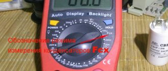
There are basic units of measurement with which you can determine the identity of a particular capacitor. These include Farad, microFarad, etc. The designation on the elements of these units, respectively, is: F, μF.
conclusions
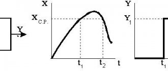
- Changing the relative duration of the periodic connection of an additional capacitor in parallel with the main one while maintaining a voltage on the disconnected capacitor equal to the voltage on the main capacitor allows you to smoothly regulate the equivalent capacitance.
- At a sufficiently high switching frequency, the capacitance control circuit can be replaced with the required accuracy by its equivalent limiting continuous model.
Literature
- Baskakov S.I. Radio engineering circuits and signals. M: Higher school. 2003.
- Toroptsev N. D. Aviation asynchronous generators. M: Transport. 1970.
- Korshunov A.I. Limit continuous model of a system with high-frequency periodic changes in structure // Izv. universities Instrumentation. 2009. T. 52, No. 9.
Variable Capacitance Cells
A variable capacitor has parts such as sections of plates made of metallic material. One of these sections can move smoothly in relation to the second. During this movement, it happens that the plates of the moving part, that is, the rotor, are most often inserted into the gaps existing between the plates of the stationary part, the stator. Thanks to this movement, the following happens. The area of overlap of one plate by another changes, as a result of which the capacitance of the variable capacitor also changes.
The dielectric in such elements is most often air. Although it is worth noting that, if we talk about equipment with small dimensions, for example, about transistor pocket receivers, then they often use variable capacitors with a solid dielectric. Wear-resistant and high-frequency raw materials are used as this element. Most often it is fluoroplastic or polyethylene.
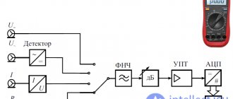
Converters
Variable capacitance is sometimes used to convert physical phenomena into electrical signals.
- In a condenser microphone (commonly known as a condenser microphone), the diaphragm acts as one plate of the capacitor, and vibrations cause changes in the distance between the diaphragm and the stationary plate, changing the voltage maintained across the capacitor plates.
- Some types of industrial sensors use a capacitor element to convert physical quantities such as pressure, displacement or relative humidity to an electrical signal for measurement purposes.
- Capacitive sensors can also be used in place of switches, such as in computer keyboards or "touch buttons" for elevators that do not have user-movable parts.
KPI parameters
The main parameter for such parts, which will help determine the ability of the device to operate in an oscillatory circuit, has become the minimum and maximum capacitance. This indicator is most often indicated next to the variable capacitor itself on the device diagram.
It is worth noting that in devices such as radio receivers and radio transmitters, several oscillatory circuits are used at once. In order to configure the operation of several parts at once, capacitor blocks are used. One block most often consists of two, three or more KPI sections.
The rotor part for such units is usually mounted on one common shaft for all variable capacitors. This is done for convenience, since when just one rotor rotates, it becomes possible to change the capacity of all devices located in this section at once.
Recommendations
- Technical section of the home page G3NPF and M1AIM (capacitors)
- George Washington Pierce: Principles of Wireless Telegraphy
, McGraw-Hill Book Company, New York, 1910, para. 114. (Photograph of Cord's rotary condenser). - Frenzel, Louis (29 January 2009). “Automatic digital antenna tuning is suitable for a variety of wireless applications.” Electronic design
. Archived from the original on August 3, 2014. Retrieved January 23, 2017.
KPI schemes
It is important to note that in the diagram, each capacitor that is included in the block is displayed separately. In order to indicate that the capacitance of the variable capacitor of this block and the remaining elements can be changed by means of just one knob controlling the entire block, those arrows that indicate regulation should be connected by a single dashed line of mechanical connection.
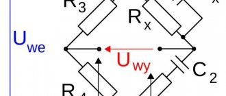
It is worth noting that there are some varieties of such KPIs. One of the types is differential capacitors, which have found their application, for example, in the arms of capacitive bridges. A special feature of this type is that it has two rows of stator plates and one row of rotor plates. The arrangement of the groups of plates is as follows: when one group leaves the gap, the second immediately takes their place. At this moment, the capacitance of the differential type AC capacitor will decrease between the plates of the first stator group and the rotor group. But between the second group of stator plates and the rotor group, this figure will increase. Thus, the total value will remain unchanged all the time.
Adjustment KPIs
Another type of KPI is tuning capacitors. They are used to set the initial capacitance of the oscillating circuit, which will determine the maximum frequency of its tuning. The capacitance of the capacitor in an alternating current circuit of this type can be varied from several units of picoFarads to several tens of picoFarads. In some cases, higher capacity can be achieved.
The main requirement for these types of KPIs is the ability to smoothly change the capacity indicator. Also, this capacitor must ensure reliable fixation of the rotor in a given position.
PDA design
The most common type of trimmer capacitor is ceramic. The design of this device is as follows. The base of the part is a ceramic stator, as well as a movable base mounted on it in the shape of a disk - the rotor. The plates in this element are thin layers of silver. They are applied by burning. Burning is carried out on the stator, as well as on the outer wall of the rotor.
In order to change or determine the capacitance of a variable capacitor of this type, it is necessary to rotate the rotor. If we talk about the simplest equipment, then it most often uses a wire tuning capacitor. This part consists of a piece of copper wire with a diameter of 1-2 mm. The length of this element is 15-20 mm. An insulated wire with a diameter of 0.2-0.3 mm is wound onto the wire very tightly, turn to turn. In order to change the capacitance in this device, it is necessary to unwind the wire. To prevent the winding from slipping off at this time, it is necessary to impregnate it with any insulating compound.
Resistance capacitance of a capacitor in an alternating current circuit
It is important to note here that current in a circuit in which there is a capacitor can only flow if the applied voltage changes. You also need to understand that the strength of the current that will circulate in the circuit during the discharge and charge of this element will be greater, the greater the capacitance of the capacitor itself, and will also depend on the speed at which changes in the electromotive force (EMF) occur.
One more property. A capacitor with variable capacitance, which is connected to a circuit with alternating current, will be a resistance for this circuit. In other words, the value of the capacitance resistance will be the smaller, the greater the value of the capacitance itself and the higher the frequency of the operating current. However, this statement is true only for a circuit in which the current is alternating. The capacitance of the capacitor is equal to infinity, that is, its resistance will be infinite if such an element is placed in a circuit with direct current.
Capacitors | Operating principle and marking of capacitors
Capacitors perform many useful functions in electronic device circuits despite their simple design. If you disassemble several radio-electronic devices to detail and count them, it turns out that the number of elements discussed in this article will exceed the number of other individual radio-electronic devices, including resistors. In view of this circumstance, we should pay special attention to the design, structure and principle of operation of capacitors.
Operating principle of a capacitor
To better understand the principle of operation of a capacitor, consider its design. The simplest capacitor consists of two metal plates called plates. Between the plates there is a dielectric, that is, a substance that practically does not allow electric current to pass through. The covers, as a rule, have the same geometric dimensions (square, rectangle, circle) and are equal in area. The plates are made of aluminum, copper or precious metals. The presence of precious metals in the composition of the plates causes an increased hunt on radio markets for Soviet samples of this radio-electronic element.
Dry paper, ceramics, porcelain, air, etc. are used as a dielectric located between the plates.
The principle of operation of a capacitor is as follows. If one plate is connected to the plus of an electric current source, and the second to the minus, then both plates will be charged with opposite charges. Charges will continue to be held on the plates even after the power source is disconnected. This is explained by the fact that charges of different signs (“+” and “-”) tend to attract each other. However, this is prevented by a dielectric (material that does not conduct charges) located in their path. Therefore, the charges distributed over the entire area of the plates remain in their places and are held by forces of mutual attraction.
Dielectric polarization
This phenomenon is called the accumulation of electrical charges. And a capacitor is called an electric field accumulator, since an electric field acts around each charge, under the influence of which the dielectric is polarized, that is, its molecules become polar - they have clearly defined positive and negative poles. The poles of the molecules of a non-conducting substance are oriented along the lines of the electric field created by the charges located on the plates. Moreover, the negative pole of the molecule is directed towards the positive plate, and the positive pole - towards the negative one.
The ability to accumulate electrical charges is characterized by the capacitance of the capacitor, hence its designation on the drawings of electrical circuits C (English: apacitor - accumulator). Similar to the capacity of a vessel - the larger the capacity of the vessel, the more liquid it can hold.
The capacitance of a capacitor refers to the main parameter and is measured in farads [ F ], named after the outstanding English physicist Michael Faraday.
Please note: it is correct to say not “one farad”, but “one farad”.
A capacitor has a capacitance of one farad, which accumulates a charge of one coulomb if a voltage of one volt is applied to the plates.
Previously, one could often hear the statement that a capacity of 1 F is a lot - almost the capacity of our planet. However, now, with the advent of supercapacitors, they no longer say this, since the capacity of the latter reaches hundreds of farads. However, most electronic circuits use drives smaller than C —picofarads, nanofarads, and microfarads.
Capacitor capacitance calculation
Calculating the capacitance of capacitors is quite simple. It is determined by three parameters: plate area S , distance between plates d and dielectric type ε :
The physical meaning of this formula is as follows: the larger the area of the plates, the more charges can be located (accumulated) on it; The greater the distance between the plates and, accordingly, between the charges, the lower the force of their mutual attraction - the weaker they are held on the plates, so it is easier for the charges to leave the plates, which leads to a decrease in their number, and therefore a decrease in the capacity of the electric field storage device.
Dielectric constant ε shows how many times the charge of a capacitor with a given dielectric exceeds the charge of a similar storage device if there is a vacuum between its plates of the same area and located at the same distance. For air, ε is equal to unity, that is, practically no different from vacuum. Dry paper has a dielectric constant twice that of air; porcelain - four and a half times ε = 4.5. Capacitor ceramics have ε = 10..200 units.
An important conclusion follows from this: in order to obtain maximum capacity while maintaining the same geometric dimensions, a dielectric with maximum dielectric constant should be used. Therefore, ceramics are used in widely used flat-plate capacitors.
Capacitor in DC and AC circuits
Since there is a dielectric between the plates of the capacitor, electric current cannot flow from one plate to another, therefore, an open circuit is formed for direct and alternating current. Therefore, we can confidently say that the capacitor does not allow direct current to pass through! It also does not allow alternating current to pass through, but the alternating current constantly recharges the storage device, which creates the picture of alternating current passing through the plates of the capacitor.
If a constant voltage is applied to the plates of a discharged capacitor, an electric current will begin to flow in the circuit. As it charges, the current will decrease and if the voltages on the plates and the power source are equal, the current will stop flowing - a break in the electrical circuit will form.
Fixed capacitors
The capacity of such capacitors is not intended to be changed during the operation of radio-electronic equipment. They are distinguished by the widest variety and geometric sizes - from a match head to huge cabinets and are most widely used in printed circuit boards of electronic devices. The most common specimens are shown in the photo.
Variable capacitors KPE
To change the capacitance of a separate unit of an electrical circuit directly during operation of an electronic device, variable capacitors (VCA) are used. KPIs were mainly used in old-style receivers to tune the oscillating circuit to the resonant frequency of the radio station. However, now, instead of KPIs, varicaps are used - semiconductor diodes, the capacitance of which is determined by the value of the supplied reverse voltage. Now it is enough to change the voltage supplied to the varicap to change the capacitance of the latter, and as a result, the frequency of the oscillatory circuit.
As a rule, KPI consists of a number of parallel metal plates separated by air, so their dimensions are very significant. Varicaps, on the contrary, have much smaller dimensions, which is why they replaced the KPE.
Trimmer capacitors
Trimmer capacitors are used in final tuning units of electronic equipment. Most often they are found in various kinds of oscillatory circuits or in devices related to frequency formation; in measuring instruments. They can also be found in digital oscilloscope probes. There they are used to eliminate the intrinsic capacitance of the measuring probes, which makes it possible to eliminate errors as much as possible when performing measurements of high-frequency signals.
Electrolytic capacitors
The main difference and advantage of electrolytic capacitors is their large capacity with small dimensions. Due to this property, they are widely used as electrical filters to smooth out rectified voltage, which makes them an integral part of any power supply.
Structurally, the electrolytic capacitor is made of aluminum foil, which serves as one of the plates. The foil is wound into a roll in the form of a cylinder, which allows you to increase the active area of the lining. An oxide layer is applied to the foil, which is a dielectric. The second plate is an electrolyte or semiconductor layer. For this reason, electrolytic capacitors are polar (non-polar ones are used much less frequently), that is, polarity must be observed when connecting them to the circuit. Otherwise, it will fail, most often it will explode. Therefore, you should be extremely careful when connecting such a radio-electronic element to an electrical circuit, which is often forgotten to do when replacing this component.
The negative terminal of the new electrolytic capacitor is shorter than the positive one, and the corresponding minus sign is applied to the housing next to it. In Soviet marking, on the contrary, the positive terminal is marked, on the side of which a “+” sign is applied to the housing.
Also, the housings of electrolytic capacitors must contain the values of three main parameters: nominal capacitance value , maximum permissible voltage and maximum operating temperature .
If everything is clear with the capacity and permissible temperature, then special attention should be paid to the voltage.
An electrolytic capacitor must not be supplied with a voltage greater than that indicated on the housing . Otherwise it will explode. Most developers of electronic equipment advise not to exceed the voltage on the plates more than 80% of the permissible value.
Designation of capacitors in circuits
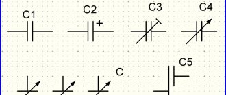
In electrical diagram drawings, the designation of capacitors is strictly standardized. However, this radio-electronic element can always be recognized in the circuit by two parallel, adjacent vertical lines. Two vertical lines indicate two facings. These dashes are signed with the Latin letter C , next to which the serial number of the element in the circuit is indicated, and below or on the side the capacitance value in microfarads or picofarads is indicated.
Capacitor markings
As electronics develops, so does the element base. Since many countries produce their own radio-electronic elements, their markings differ from the markings of radio-electronic elements in other countries. Therefore, in the first stages of industrial electronics production, many different types of marking were used, but the desire for unification led to more or less streamlining. This made it possible to bring the marking of capacitors to general rules. And the advantage here is obvious - a radio-electronic element produced in one country can now quite easily be matched with an analogue produced in another country. It would be ideal to reduce all types of designations and markings to a single type, which has already been almost completely accomplished.
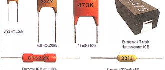
However, Soviet capacitors, distinguished by a small but varied marking, are still in wide circulation. Everything was involved in Soviet markings - numbers, letters and colors. Moreover, both numbers and letters, as well as colors, numbers and letters, were applied to the housings of the elements. The numbers indicate the value, the letters indicate the units of measurement.
The more common type of marking consists of numbers that indicate the capacity in picofarads , not to be confused with farads! You should always remember that, unlike resistors, which are marked in ohms, the basic dimension, regardless of the marking method, is picofarads (if the numbers are separated by a comma, then microfarads ). In general, capacitance starts from picofarads .
Also, previously only color marking was used - a solid color with a colored dot. The parameters can only be determined using the reference book.
The types of markings discussed above are gradually going out of use, but they are always remembered by specialists who repair Soviet equipment in which radioelements have the “old” designation.
The most successful and perfect way to designate electronic elements is digital coding. Digital coding of capacitors, like resistors, involves the use of only three digits. This approach allows for many combinations to be implemented. The two digits on the left indicate the mantissa, that is, the significant number, and the last - third digit shows how many zeros need to be added to the previous two digits. 153 is indicated on the drive case , then its capacity is 15 × 10 3 = 15000 pF = 15 nF = 0.015 μF.
In addition to capacity, drives are characterized by a number of basic parameters, which are discussed below.
Marking of SMD capacitors
The marking of SMD capacitors can be applied to the case in the form of digital coding, but in the vast majority it is a somewhat confusing encryption consisting of one or two letters of the Latin alphabet. If there are two letters, then the first one indicates the manufacturer, which interests us to a lesser extent. But the second or only letter denotes the mantissa, in the same way as in digital coding. The remaining digit shows the number of zeros after the mantissa. You can decipher the digital value of a letter using the table below.
SMD drives with similar characteristics also differ in size. A number of standard sizes are shown in the table and figure below. It is especially important to take into account the dimensions of radio-electronic elements when designing printed circuit boards.
The marking of electrolytic SMD capacitors is practically no different from their output counterparts. A negative pad is indicated by a black mark on the flat side of the housing on the side of the corresponding pad. The permissible voltage in volts and capacitance in microfarads are also indicated.
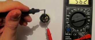
Quite often there are cases that do not have any markings on them. Only a capacitance meter can help here.
Series connection of capacitors
Connecting capacitors in series allows you to apply a higher voltage to their plates than to a separate storage device. The voltage on the plates is distributed depending on the capacitance of the element.
If two drives have the same capacity, then the supplied voltage is distributed equally between them. However, the total capacity will be half that of a separate drive.
In general, the rule to remember is that when capacitors are connected in series together, they can withstand higher voltages, but this comes at the cost of reduced capacitance.
Parallel connection of capacitors
This connection method is the most common in practical applications, since the capacity of one drive is not always enough, especially in electrical filters of high-quality power supplies. Parallel connection of capacitors realizes the summation of the capacitances of individual storage devices. This is quite easy to remember, based on the formula above, which shows that as the area of the plates increases, the capacitance increases.
Therefore, when connecting capacitors in parallel, there is a kind of increase in the area of the plates, due to which they are able to accumulate a larger number of electrical charges.
The main parameters and ratings of capacitors are discussed here.
More articles on this topic
- Zener diode | Operating principle and marking of zener diodes
- Characteristics of capacitors
- RESISTORS | Resistor markings
- Proteus | Simulation of microcontroller operation
Basic parameters for KPIs
There are several basic parameters for this type of capacitor.
One of the main ones is the law of change in capacitance. This law determines the nature of the change in capacitance. The change in this parameter will occur depending on the angle of rotation or on the linear movement of the moving part of the capacitor plates in relation to their stationary parts.
Another property is temperature stability. This indicator directly depends on the design of the capacitor itself. Most often, this indicator is positive, and for capacitors with air as a dielectric, the indicator does not exceed (200:300) 10-61/deg. If we talk about capacitors with a solid dielectric, then their value exceeds this indicator.