Half-wave rectifier circuit
Figure 1 shows the circuit of a half-wave rectifier with voltage doubling. The circuit can be used both independently and as a component element of multi-link serial multipliers.
Rice. 1. Diagram of a half-wave rectifier with voltage doubling.
Figure 2 shows a parallel circuit of a full-wave rectifier with voltage doubling (Latour circuit). This UN as a rectifier can be considered as two half-wave, connected (secondary winding of transformer T1 - diode VD1 - capacitors C1, C3; secondary winding of the transformer - diode VD2 capacitors C2, C4) in series. Double the voltage at its output is obtained as a result of the addition of separately rectified voltages of different polarities.
Rice. 2. Parallel circuit of a full-wave rectifier with voltage doubling (Latour circuit).
Voltage converter with stable 30V
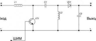
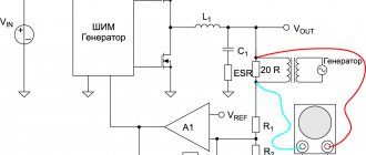
The voltage converter (Fig. 12) allows you to obtain a stabilized voltage of 30 V at the output. A voltage of this magnitude is used to power varicaps, as well as vacuum fluorescent indicators.
Rice. 12. Circuit of a voltage converter with a stabilized output voltage of 30 V.
On a DA1 chip of type KR1006VI1, a master oscillator is assembled according to the usual circuit, producing rectangular pulses with a frequency of about 40 kHz.
A transistor switch VT1 is connected to the output of the generator, which switches the inductor L1. The amplitude of the pulses when switching the coil depends on the quality of its manufacture.
In any case, the voltage on it reaches tens of volts. The output voltage is rectified by diode VD1. A U-shaped RC filter and a zener diode VD2 are connected to the output of the rectifier. The voltage at the output of the stabilizer is entirely determined by the type of zener diode used. As a “high-voltage” zener diode, you can use a chain of zener diodes having a lower stabilization voltage.
Series multi-element half-wave rectifier
A series multi-element half-wave rectifier (Fig. 3) with voltage multiplication is most often used at low (up to 10...15 mA) load currents.
Its circuit consists of half-wave rectifiers - links, in the following algorithm - one link (diode and capacitor) is simply a half-wave rectifier, consisting of a diode and a capacitor (rectifier and filter), two links - a voltage multiplier in half, three - in three times, etc.
The capacitance values of each link are in most cases the same and depend on the frequency of the supply voltage and current consumption [9].
Rice. 3. Circuit of a multi-link half-wave voltage multiplier.
It is convenient to consider the physical processes of increasing voltage in a multi-section half-wave (Fig. 3) UN when applying an alternating sinusoidal voltage to it. The UN works as follows.
With a positive half-wave voltage at the lower terminal of the secondary winding T1, current flows through diode VD1, charging capacitor C1 to the amplitude value.
With a positive half-wave of the supply voltage at the lower terminal of the secondary winding T1, the sum of the voltages on the secondary winding and the voltage on the capacitor C1 are applied to the anode VD2; as a result of which current passes through VD2, the potential of the right plate of C2 relative to the common wire increases to double the input voltage, etc. It follows that the more links, the greater the constant voltage (theoretically) can be obtained from the UN.
For a correct understanding of the formation and distribution of potentials that arise on radioelements during the operation of a voltage source, we assume that one input pulse (IP) fully charges capacitor C1 (Fig. 3) to a voltage of +U.
Let's imagine the second positive pulse arising at the upper terminal of T1 and arriving at the left plate C1 according to the diagram in Fig. 3, also in the form of a capacitor (Ci) charged to voltage +U.
Their joint connection (Fig. 4) will take the form of series-connected capacitors. The potential at C1 relative to the common wire will increase to +2U, VD2 will open, and capacitor C2 will charge to +2U.
Rice. 4. Voltage multiplier circuit.
When a pulse of +U appears on the lower terminal of T1 and is summed in the same way with a voltage of +2U on capacitor C2, a voltage of +3U will appear through the opened VD3 to C3, etc.
From the above reasoning, we can conclude that the voltage value relative to the “common” wire (Fig. 3) only on C1 will be equal to the amplitude value of the input voltage, i.e. +U, on all other multiplier capacitors the voltage will increase stepwise in steps of +2U.
However, for the correct selection of the operating voltage of the capacitors used in the UL, what matters is not the voltage on them relative to the “common” wire, but the voltage applied to their own terminals. This voltage only at C1 is +U, and for all others it is equal to +2U, regardless of the multiplication stage.
Now let’s imagine the end of the action time of the VI pulse as the closure of the capacitor C (Fig. 4) with a jumper (S1). Obviously, as a result of the short circuit, the potential on the anode VD2 will drop to +U, and a potential of 2U will be applied to the cathode. Diode VD2 will be closed by reverse voltage 2U-U=U.
From this we can conclude that a reverse voltage is applied to each UN diode relative to its own electrodes, no more than the amplitude value of the supply voltage pulse. For the output voltage of the UN, all diodes are connected in series.
Pulse type inverting converter
A pulse-type inverting converter contains the same combination of basic elements, but again in a different connection (Fig. 3): a series chain of switching element S1, diode VD1 and load resistance RH with filter capacitor C1 is connected to the power source.
Inductive energy storage L1 is connected between the connection point of the switching element S1 with the diode VD1 and the common bus.
Rice. 3. Pulse voltage conversion with inversion.
The converter works like this: when the key is closed, energy is stored in an inductive storage device. Diode VD1 is closed and does not pass current from the power source to the load. When the switch is turned off, the self-inductive emf of the energy storage device is applied to a rectifier containing diode VD1, load resistance Rн and filter capacitor C1.
Since the rectifier diode passes only negative voltage pulses into the load, a voltage of a negative sign is formed at the output of the device (inverse, opposite in sign to the supply voltage).
Practical schemes for HF and VHF
Shortwave radio amateurs involved in the independent manufacture of radio equipment are familiar with the problem of making a good power transformer for the output stage of a transmitter or transceiver.
The circuit shown in Fig. 2 will help solve this problem. The advantage of practical implementation is the use of a ready-made power transformer (PT) from a unified tube television (ULT) of the second class, which is not in short supply due to the departure of old equipment, which can be used as a power transformer to power the power amplifier (PA) of a radio station of the 3rd category.
The recommended technical solution allows you to obtain from the ST all the necessary output voltages for the PA without any modifications. The ST is made on a PL type core, all windings are structurally made symmetrically and have half turns on each of the two coils.
Such a CT is convenient both for obtaining the required anode voltage and filament voltage, because allows the use as an output in the PA of both a lamp with a 6-volt filament (type 6P45S) and a lamp (type GU50) with a 12-volt filament, for which it is only necessary to connect the filament windings in parallel or in series. The use of a doubler will allow you to easily obtain a voltage of 550...600 V at a load current of about 150 mA.
This mode is optimal [3] for obtaining a linear characteristic for the GU50 lamp when operating on SSB. By connecting the filament windings in series (used in TV to power the filament lamps and kinescope) and using [3] UN according to the circuit in Fig. 3, you can obtain a source of negative bias voltage for the control grids of the lamps (about minus 55.65 V).
Due to the small current consumption in the control grid, non-polar capacitors of 0.5 µF at 100-200 V can be used as capacitors of such a voltage control unit.
The same windings can also be used to obtain the switching voltage of the “receive-transmit” mode. When constructing an output stage with a grounded grid, the control grid is connected to a negative voltage source (UN 55.65 V), the cathode is connected through a choke (015 mm, n=24, PEV-1 00.64 mm) to -300 V, and + is supplied to the anode 300 V, excitation voltage is supplied to the cathode through a capacitor [3].
You can connect the control grid directly to -300 V, the cathode is connected to -300 V through two parallel-connected chains, each of which consists of a D815A zener diode and a 2-watt 3.9 Ohm resistor [4]. The excitation voltage in this case is supplied to the cathode through a broadband transformer.
If the output stage of the PA is made according to a circuit with a common cathode, then +600 V is supplied to the anode, and +300 V is supplied to the screen grid [6] from the connection points C1, C2, C3, C4 (the -300 V output is connected to the “common” wire RXTX), which allows you to get rid of powerful damping resistors in the screen grid circuit, which uselessly release large thermal power. The control grid is supplied with a negative bias of -55.65 V from the previously mentioned UN.
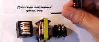
To reduce the level of supply voltage ripple in the rectifier, you can also use standard chokes (L1, L2, Fig. 2) of the power supply filter of the same ULT type DR2LM with a primary winding inductance of about 2 H. Winding data for ST and DR2LM are given in [5].
Lighting engineering
An example of using a voltage multiplier by four [1] is the circuit for starterless starting of a daytime running light (LDS), shown in Fig. 5, which consists of two voltage doublers connected in series for direct current and in parallel for alternating current.
Rice. 5. Circuit of a voltage multiplier by four for starterless starting of a daytime running lamp.
The lamp lights up without heating the electrodes. Breakdown of the ionized gap of the “cold” LDS occurs when the ignition voltage of the LDS is reached at the output of the UN. The ignition of the LDS occurs almost instantly.
A lit lamp shunts, with its low input resistance, the high output resistance of the UN, the capacitors of which, due to their small size, cease to function as sources of increased voltage, and the diodes begin to work as ordinary valves.
The 2-winding inductor L1 (or two 1-winding inductors) is used to smooth out the ripples of the rectified voltage. The voltage drop of the supply network is approximately evenly distributed across the ballast capacitors C1, C2 and LDS, which are connected in series with alternating current, which corresponds to the normal operating mode of the LDS.
When used in this circuit, LDS with a cylindrical part diameter of 36 mm ignite without any problems; LDS with a diameter of 26 mm ignite worse, since due to the peculiarities of their design, the ignition voltage of even new lamps without filament heating can exceed 1200 V.
Where is the device used?
Multipliers have found their application in different types of devices, these are: laser pumping systems, X-ray wave radiation devices in their high voltage units, for illuminating displays of liquid crystal structure, ion pumps, traveling wave lamps, air ionizers, electrostatic systems, particle accelerators, copiers, televisions and oscilloscopes with picture tubes, as well as where high direct electricity of low current is required.
A television
It is known that the output horizontal scan transformer (HVT) is one of the stressed nodes in a television set (TV). As the evolution of the development of the circuitry of this unit shows, with the transition from tube TVs to color TVs, due to an increase in power consumption from a high voltage source (the current consumption of a black and white kinescope with a diagonal of 61 cm at the second anode is about 350 μA, and a color one is already 1 mA !), TV designers were constantly looking for ways to improve its reliability.
Circuit solutions for obtaining high voltage to power the second anode of the kinescope, which were used in all models of tube TV, took place only in the first modifications of the ULPTST, and then instead of the step-up winding of the TVS (almost equal in the number of turns of the anode [5]), they began to use UN, which their electrical strength, and therefore reliability, significantly exceeded similar parameters of the winding unit.
Rice. 6. Voltage multiplier circuit with tripling, from the Yunost TV.
UN began to be used almost immediately in domestic black-and-white portable TVs. For example, in the TV “Yunost 401” [10] a voltage tripling VN circuit is used, shown in Fig. 6.
When implementing practical UN circuits, it matters to which point of the UN circuit (1 or 2, Fig. 3) the “common” wire of the circuit in which it will be used will be connected, i.e. “phasing” of UN. This is easy to verify using an oscilloscope.
When carrying out measurements on an unloaded UN (Fig. 3), it is clear that on odd links the value of the variable component is almost equal to the supply voltage, and on even links it is practically absent.
Therefore, when using voltages in real designs only from even or only from odd multiplication links, this fact should be taken into account when connecting the voltage booster to the power source accordingly.
For example, if the “common” wire (Fig. 3) is connected to point 2, then the operating voltages are removed from the even links, if with point 1 - from the odd ones.
When using both even and odd links of one voltage amplifier, in order to obtain a constant voltage from a link in which there is an alternating component, it is necessary (especially with a capacitive load) to include (Fig. 7) another link (diode and capacitor) between the multiplier link and the load.
The diode (VDd) in this case will prevent the AC component from shorting through the load, and the capacitor (Cdf) will act as a filter. Naturally, the capacitor Cdf must have an operating voltage equal to the full DC output voltage.
Rice. 7. Connecting another link to the voltage multiplier.
We should also not forget about the negative impact on the reliability of operation of multi-element ultrasonic voltage leakages, which are always present in radioelements and materials when they operate under high voltages, which imposes certain restrictions on the actually achievable value of the output voltage.
A practical version of the UN circuit design with multiplication by three is shown in Fig. 6; for four - in Fig. 4; for five - in Fig. 8, Fig. 9; by six - in Fig. 10.
Rice. 8. Voltage multiplier circuit with multiplication by four.
Rice. 9. Voltage multiplier circuit with multiplication by five.
Rice. 10. Voltage multiplier circuit with multiplication by six.
This article discusses only part of the UN circuitry that was used previously and is currently used in household appliances and amateur radio design. Some varieties of UN circuitry, the operating principles of which are similar to those discussed, were published in [9].
In the literature and in communication with radio amateurs, one often encounters confusion regarding UN in terms. For example, it is argued that if the voltage is marked 8.5/25-1.2 or 9/27-1.3, then this is a voltage tripler. According to the circuit design, these UN are multipliers by five.
The marking carries information only that when a voltage with an amplitude of 8.5 kV is applied to the input of the UN, it ensures that at its output an average value of a constant (positive) voltage of 25 kV (with the current consumed by its load being about 1 mA), i.e. e. The marking speaks only about its input and output parameters.
To obtain high voltage in the TV, a pulse voltage is used that occurs in the secondary winding of the fuel assembly during the reverse stroke of the beam, following with a frequency of 15625 Hz, with a (positive) pulse duration of about 12 μs and a duty cycle of about five.
With a large multiplication factor, the voltage drop in the forward direction on the rectifier columns, such as UN rectifiers, is also significant. For example, for a 5GE600AF column, when operating as a single rectifier, the voltage drop in the forward direction is 800 V [7]!
From the above it follows that the UN elements also serve as an integrating circuit for the supply pulse voltage, which reduces the average value of the direct voltage relative to the input voltage (at a load current of 1 mA) to approximately 5 kV per link. It is these factors that are the main ones that influence the value of the output voltage of the UN, and not approximate arithmetic.
Historically, the use of selenium diodes as rectifiers in the first samples of UN for TV was determined by the level of technology achieved at that time, their low cost, as well as their soft electrical characteristics, which made it possible to connect in series an almost unlimited number of diodes.
It is obvious that selenium rectifiers, due to their high internal resistance, can withstand short-term overloads better than silicon rectifiers. As the technology for manufacturing silicon diodes improved, silicon pillars of the KTs106 type began to be used in UN TV.
When repairing TV, even a preliminary assessment of the possible presence of defects in the rectifying elements of the UN avometer is impossible. The physical meaning of this phenomenon is that in order to open one silicon diode, a potential difference of about 0.7 V must be applied to it in the forward direction.
If, for example, instead of a KTs106G pole, we use an equivalent of individual KD105B diodes (iobr = 400 V), then to obtain a reverse voltage of 10 kV, a chain of 25 diodes connected in series will be required, as a result of which the required voltage for opening them will be 17.5 V , and the avometer allows you to apply only 4.5 V!
The only thing that can be unequivocally stated after measuring the voltmeter with an ohmmeter is that when checking a working voltmeter, the ohmmeter needle should not deviate when measuring the resistance between any of its electrodes.
A simple solution for preliminary testing of the operability of UN elements using a voltmeter method was proposed in [8]. The essence of the proposal is to use for this purpose an additional source (A1) of direct voltage (DC) 200...300 V and an avometer operating in the mode of a DC voltmeter at a limit of 200.300 V. Measurements are made as follows.
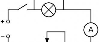
The avometer is switched on (Fig. 11) in series with the same pole of the IPN and the tested rectifier column or UN. Verification algorithm.
Rice. 11. Scheme for connecting the avometer to the rectifier column.
If, when measuring a diode in opposite directions, the voltmeter readings:
- differ significantly, then it is serviceable;
- equal to the maximum voltage of the IPN, then it is broken;
- are small, then it is torn off;
- intermediate values indicate the presence of significant leaks in it.
The suitability of the elements of the tested rectifier is determined empirically for a specific brand by a statistical method of comparison with the values of the voltage drop obtained practically from measurements in the forward and reverse directions of a serviceable pole or diode of the same brand.
For radio amateurs who are engaged in repairing television equipment at the customer’s home, for preliminary testing of the operability of UN elements using the voltmeter method, it is more convenient (based on the weight and dimensions) to use the circuit shown in Fig. 12 and proposed in [12], which is powered through current-limiting capacitors from the network 220 V.
Rice. 12. Power circuit with current-limiting capacitors.
The circuit has proven itself well in practice, and in terms of circuit design it is a voltage doubling rectifier. The measurement algorithm is the same. The same circuit can also be used to eliminate certain types of interelectrode short circuits (“lumbago”) in a kinescope.
Quite often they ask whether it is possible to install UN9/27-1.3 instead of UN8.5/25-1.2? One piece of advice: you can, but be careful! It all depends on the severity of the problem and the modification of the TV. For comparison, consider the diagrams
UN8.5/25-1.2 (Fig. 8) and UN9/27-1.3 (Fig. 9). From the UN circuits it is clear that, in principle, direct replacement is possible, but the reverse is not, since they have a different number of incoming radio components.
Therefore, when installing UN9/27-1.3 in a TV ULPTsT, proceed as follows: connect the input terminals for pulse voltage and the “V” output; the wire from the fuel assembly is soldered to the corresponding input of UN9/27; the wire with the “ground” sign is connected at the shortest distance to the second contact of the fuel assembly; the wire going to the focusing varistor is connected to the “+F” terminal, and the standard focusing filter capacitor C23* (according to the factory circuit diagram on the TV) can be disconnected, since its function can be performed by capacitor C1 (Fig. 10), which is installed inside the UN. A high-voltage wire with a “suction cup” and a limiting resistor Rph is connected to the “+” terminal.
The resulting slight improvement in image quality on the TV screen as a result of such a replacement does not at all mean that this is the result of a replacement!
The reason is primarily that in UN9/27-1.3 silicon pillars of the KTs106G type are used as valves, the voltage drop on which in the forward direction (as mentioned earlier) is significantly less than on the pillars of the 5GE600AF type, which are included in UN 8.5/25-1.2.
It is by the magnitude of this difference that the voltage at the output of the UN increases, and therefore at the second anode of the kinescope, which is visually observed as an increase in brightness!
In addition, in the ULPTsT TV, when installing UN9/27-1.3, it is necessary to replace the standard “sucker” with a high-voltage resistor 4.7 kOhm Rf installed inside it) with a “suction cup” from the 3UCST TV with a 100 kOhm resistor. Rф performs three functions: it is part of a link in the smoothing RC filter for the high-voltage circuit formed by it and the capacitance of the kinescope ac-vadag Ca (Fig. 9, 10), as well as a protective resistor for direct current, limiting its value in the UN circuit in case of random short-term interelectrode breakdowns inside the kinescope (which happens very often and unpredictably in old kinescopes).
It is also a “burning fuse” that protects the fuel assembly in the event of a breakdown of the UN diodes, when the alternating voltage coming from the fuel assembly is practically shorted to the housing through Ca, the value of the reactance of which is quite small for lower-frequency currents.
Therefore, it should be borne in mind that a significantly smaller value of the total internal resistance UN9/27-1.3 with a small value (or absence for one reason or another) of Rf in cases of replacing the UN is undesirable, since it can lead to the emergence of the above malfunctions as a way out of building a TVS, and to the fire of the TV itself.
Practical recommendations for “repair” of UN8/25-1.2 are described in [8]. The essence of the “repair” is to drill out the failed VD1 (Fig. 9) using a drill with a diameter of 6 mm and replace it with a diode located outside the unit.
From inoperable TV units, with a certain skill and care, you can “get” (if you’re lucky) high-voltage capacitors, which can still serve for urgent repairs of TV modifications of ULPTsTI or UPIMCT or for experiments with other designs.
To do this, first, carefully break the UN housing with a hammer and free the capacitor housings from the compound, and then separate their leads from the mutual connections and the remains of the compound by successive chipping using side cuts. Practical disassembly of three copies of each UN brand showed that in UN8/25-1.2 the capacitors are marked K73-13 2200×10 kV on the case.
In UN9/27-1.3 (Fig. 10), which compared to UN8/25-1.2 has a larger number of elements, but smaller overall dimensions, capacitors are used (judging by the manufacturing technology and the material from which they are made) of the same type (markings are not applied to the cases), which are structurally made in the form of a three-terminal (16 mm in diameter) assembly (C2, C4 - Fig. 10) of capacitors with a capacity of 1000 pF, and a four-terminal (C1, C3, C5 - Fig. 10) assemblies with a diameter of 18 mm. Moreover, C1 has a capacitance of 2200 pF, and C3, C5 - 1000 pF each. Both assemblies are 40mm long.
Medicine
One of the “exotic” examples of the use of CN in medical equipment is its use in the design of an electroeffluvial chandelier (EL), which is designed to produce a flow of negative ions that have a beneficial effect on the human respiratory tract.
To obtain a high negative potential for the radiating part of the air ion generator, a voltage booster with a negative output voltage is used. Due to the rather large volume [2, 11] of supporting information, recommendations on the design and use of EL are beyond the scope of this article, therefore EL is mentioned for informational purposes only.