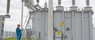
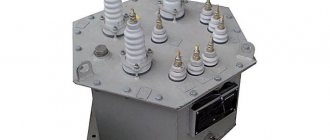
INDOOR MARKING EQUIPMENT
During operation of any transformer, regardless of type, energy losses occur, leading to heating of the working elements, especially the windings and core.
Long-term trouble-free operation of all elements, in particular insulation, directly depends on the accuracy of temperature control.
Moreover, the more powerful the device, the more efficient transformer cooling systems are needed. The main types of cooling of power transformers, technical characteristics, advantages, disadvantages and areas of use of each of them.
Cooling systems with directed oil circulation in the NDC and NC windings.
It is possible to improve the cooling of the windings and ensure a more uniform temperature distribution in them by creating forced (directed) circulation of oil in the cooling channels of the windings at the required speed, ensuring the required temperature conditions. There are two possible design options here - with single-circuit and double-circuit oil circulation schemes. In the first option, oil taken from the top of the tank passes through oil-air or oil-water coolers and is supplied to the windings. In the second option, in addition to the oil cooling circuits, similar to the DC or C systems, there are independent winding cooling circuits, and the oil taken by the pump from the top of the tank is supplied, bypassing the coolers, to the lower part of the tank and then to the winding cooling circuits. The second version of the cooling system is somewhat more complex and expensive. This cooling system allows, if necessary (for example, in transformers of maximum power) to increase electromagnetic loads, but it complicates the design of insulation and windings, as well as the technology for assembling and testing transformers (hydraulic tests of oil circulation circuits in the winding are required). Therefore, such systems are used in the domestic transformer industry for transformers with a capacity of 400 MB-A and higher.
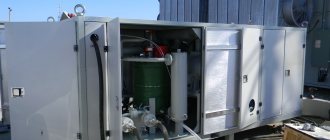
COOLING TRANSFORMERS INDOOR
Regardless of the specific use and type of cooling system of the oil transformer when it is located inside a building, the room needs ventilation, since the lack of intensive air circulation can cause a decrease in rated power.
As a rule, in enterprises, rooms for transformer and service equipment are provided in advance and have ventilation holes: in the lower part for the influx of cold air and in the upper part for the outflow of warm air.
If the room for the transformer substation is a separate building, under most operating conditions, natural air circulation is sufficient.
Forced circulation is necessary in the following cases:
- The room has a small area;
- Equipment operation is characterized by frequent overloads;
- The location of the equipment in the room leads to disruption of the natural circulation of air flows;
- The external temperature exceeds 20°C;
- Type C transformers are used.
Main advantages and disadvantages
Each practical type is accompanied by a number of technical features, advantages and disadvantages. Next, we present the main criteria by which positive or negative positions are determined:
- Temperature level. The main purpose of cooling is to maintain a natural, favorable operating environment for equipment. The latter is largely determined by the installation environment and the load level of power plants.
- Cost of implementation. Almost every energy supply company strives to reduce equipment costs, so it uses old proven solutions in the form of oil cooling.
- Degree of security. This is an important criterion that presupposes the use of one or another solution at different energy facilities. For nuclear power plants, it is preferable to use more modern and rational proposals that allow maintaining the desired temperature regime. When at a distribution network substation with low currents, type C option can be used.
Please note that in Russia, Belarus, and Ukraine, power transformers with a cooling system NMC, NDC are used.
Markings and types of transformer cooling systems
Determination of marking and type is carried out in accordance with GOST 11677-75. Full specifications and gradings are explained here. Let's look at each group separately:
- C - dry type transformers, which, due to their characteristics, can use natural air cooling. Some options come with forced air circulation and are called LEDs.
- M – electrical equipment with natural oil and air cooling. They are mainly used for distribution networks with low capacity. At large substations there are options with forced circulation of oil MK, NMK.
- D – equipment with natural oil cooling and forced air cooling. There are different versions of DC and NDC, depending on the additives in the form of the circulating technical fluid.
- H - the presented type is less common, since non-flammable dielectrics are used for implementation. In most cases, such products are less susceptible to explosions, which ensures greater safety for people and the substation as a whole.
It should be noted that in modern practice there are foreign gradations in this direction. Almost all of the mentioned transformer cooling systems are duplicated in the relevant standards.
What should the oil temperature be?
The permissible temperature indicators of the liquid dielectric are determined by the material used to make the insulating coating of the winding wires. The nominal temperature value of operating transformers with the insulation material indicated below (regardless of the cooling system) is:
- electrical varnish – up to 70°С,
The maximum oil heating temperature for transformers with an oil cooling system should not exceed 80°C.
Standards for oil temperature in power transformers using the specified cooling system are regulated by the requirements of GOST 11677-85, which defines the technical operating conditions of the specified equipment.
Reasons for heating transformers
The efficiency of a transformer, like any other electrical appliance, is below 100% - from 80% for small 10W devices to 99.5% for power transformers. Losses are released in the windings and magnetic circuit in the form of heat.
Heating of the magnetic circuit
Core losses consist of two components:
- eddy currents;
- hysteresis losses.
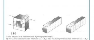
Eddy currents are induced by the transformer windings in the magnetic core, and the lower its resistance, the greater the currents and heating of the iron. To increase resistance, the iron core is not made solid, but from thin sheets isolated from each other with varnish and an oxide film. They are made not from ordinary carbon steel, but from transformer iron, with the addition of silicon, which increases the resistance of the metal.
During operation, the magnetic circuit is magnetized by a magnetic field created by the current flowing through the coils. Since the current is alternating, the field constantly changes polarity and magnetization reversal of the core occurs, releasing heat. This process is called a “hysteresis loop”, and the losses are called hysteresis losses.
Important! For each section, shape and material of the magnetic circuit there is an optimal number of winding turns. As it decreases, hysteresis losses increase, and as it increases, losses in the windings increase.
Winding heating
The conductors with which the coils are wound have active resistance. When working, an electric current flows through this resistance and energy is released, which is converted into heat.
Losses in the windings are reduced by increasing the cross-section of the wire and replacing cheap aluminum with more expensive copper, which has lower resistance, but these methods lead to an increase in dimensions or an increase in the price of the device. Therefore, when designing an electric transformer, in addition to technical calculations, economic calculations are made.
Interesting! In the 50s, to reduce losses and heating, power transformers with silver windings were designed, but due to rising prices for silver, these projects were not implemented.
Application area
Rice.
7. Practical application of dry transformers In view of the widespread use of electrical energy for all production and technological processes, dry transformers, as high-voltage converters, have a fairly wide application. They are used to supply power to ground electrified transport systems, traction and transformer substations, and power production workshops. In addition to the industrial sector, dry aggregates are used in the agricultural industry, for shopping complexes, resort centers and villages. In everyday life, they are used to supply power to apartment buildings, schools and preschool institutions.
The scope of application of low-current low-power dry transformers is practically unlimited. These are all kinds of household appliances, devices and devices for small-scale mechanization, converters and welding equipment.
M type cooling
The presented type is considered the most common due to its relative cheapness, extended service life and some other features. At distribution network substations, oil-filled transformers with natural oil circulation and without additional airflow are used. The cooling system of the M transformer has some operating nuances:
- The need to monitor the oil level and gas sampling to determine the condition of the equipment. Maintenance personnel are required to visit the distribution network substation at least once every six months.
- The structure must be sealed. Traces of leaks indicate the need for technical or major repairs.
Oil theft is considered a negative factor in operation. This is a common practice when technical fluid breaks and drains from the transformer tank. Due to barbaric actions, equipment overheats and short circuits, followed by burnout.
MARKING OF COOLING SYSTEMS ACCORDING TO INTERNATIONAL CLASSIFICATION
International standards have adopted four-letter markings for transformer cooling systems:
1. The first symbol is a designation of the type of coolant that is in direct contact with the electrically carrying windings:
- “O” - mineral oils or synthetic refrigerants with a flash point of about 300oC;
- “K” - synthetic refrigerants and insulating liquids with a flash point of more than 300oC;
- “L” - insulating liquids and oils with an undetectable flash point.
2. The second symbol is the coolant circulation mode:
- “N” - natural-forced;
- "D" - forced;
- “F” - forced in the cooling system and thermosyphon in the windings.
3. The third character is the type of external coolant;
- "A" - air;
- "W" - water.
4. The fourth symbol is the method of circulation of external coolants;
- "N" - natural;
- "F" is forced.
Cooling system D.
In transformers with a power of more than 6.3-10 MB-A, it is difficult to develop the heat-transfer surface of the tank to such an extent as to ensure a given level of heating. This becomes understandable if we consider that, according to the laws of growth in a series of similar transformers (i.e., in those in which the corresponding linear dimensions are proportional), with constant electromagnetic loads (induction in the magnetic core and current density in the windings), losses grow in proportion to the cube of linear dimensions, while the cooling surfaces grow in proportion to the square of these dimensions. Therefore, it is necessary to take additional measures to enhance cooling by blowing fans onto the radiators. This increases the heat transfer coefficient and, accordingly, the heat removal from radiators by 1.5–2 times. When the temperature of the upper layers of oil drops to 50C, if the load current is less than the rated one, the fans are turned off.
DC cooling system.
In transformers with a capacity of about 100 MB-A or more, the emitted losses are so significant that to remove them it is necessary to use special oil-air coolers, blown by fans and equipped with pumps for forced oil circulation. To increase the efficiency of blowing, the pipes in such coolers have a highly developed ribbed outer surface. Thanks to forced oil circulation, a more uniform distribution of oil temperature across the height of the tank is achieved. The difference in oil temperature at the top and bottom of the tank is in this case less than 10°C, while with natural circulation it reaches 20-30°C. Coolers currently produced by the domestic industry have a heat output of 160-180 kW. If the cooling system is turned off, the transformers can remain on for a very short time, since the heat-transferring surface of the tank is not enough even to remove no-load losses. The disadvantage of such a cooling system is that the heat transfer from the windings to the oil remains almost the same as with natural convection, since forced circulation of oil occurs only in the area between the outer winding and the wall of the transformer tank.
Technical specifications
Before installing a dry-type transformer, it is important to accurately determine its technical characteristics, which will provide basic information about the suitability of the unit for operation in certain conditions.
Among the most important parameters are:
- Rated power - determines the volume of processed electricity for a dry transformer.
- Rated voltage - shows the value of the voltage level that can be supplied to each of the high, medium and low potential windings.
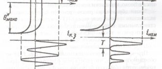
- Overload factor - shows by what amount the workload can exceed the rated current value.
Rice. 6. Overload capacity
- No-load and short circuit loss coefficients.
- The degree of dust-moisture resistance and climatic performance determines the external conditions under which the unit can be operated and the insulation strength is maintained.
- Overall dimensions and weight of a dry-type transformer.
Cooling system C.
This very efficient and compact cooling system is used for powerful transformers when there is a sufficient amount of water (hydro stations, very powerful thermal stations). It allows you to abandon the DC cooling system, which becomes quite cumbersome with very high power transformers. This cooling system is based on the use of oil-water coolers with smooth or finned pipes and the movement of water through the pipes and oil in the inter-tube space. Thanks to constructive measures, a zigzag movement of oil in the cooler with transverse flow around the tubes is ensured. Large heat removal (up to 1000 kW or more) and small overall dimensions of oil-water coolers are achieved due to an increase in the heat transfer coefficient from the pipe wall when cooled with water. When this cooling system is turned off, as with the DC system, the transformers can also remain in operation for a very limited time. The disadvantage of this: the cooling system in terms of the intensity of cooling of the windings is the same as the DC cooling system.
Cooling options C, SG
Unlike the oil cooling system of transformers, type C options do not use any liquid to adjust the temperature regime. Temperatures are reduced by natural air circulation, which is acceptable in the following cases:
- Transformer up to 63 kVA, which have a normal operating environment and light load.
- Power equipment that is used in low temperature conditions.
- Temporary construction site where the duration of use of the products is not important.
In other cases, it is recommended to focus on the solutions described above. This will extend the service life and save significant money.
Cooling systems with directed oil circulation in the NDC and NC windings.
It is possible to improve the cooling of the windings and ensure a more uniform temperature distribution in them by creating forced (directed) circulation of oil in the cooling channels of the windings at the required speed, ensuring the required temperature conditions. There are two possible design options here - with single-circuit and double-circuit oil circulation schemes. In the first option, oil taken from the top of the tank passes through oil-air or oil-water coolers and is supplied to the windings. In the second option, in addition to the oil cooling circuits, similar to the DC or C systems, there are independent winding cooling circuits, and the oil taken by the pump from the top of the tank is supplied, bypassing the coolers, to the lower part of the tank and then to the winding cooling circuits. The second version of the cooling system is somewhat more complex and expensive. This cooling system allows, if necessary (for example, in transformers of maximum power) to increase electromagnetic loads, but it complicates the design of insulation and windings, as well as the technology for assembling and testing transformers (hydraulic tests of oil circulation circuits in the winding are required). Therefore, such systems are used in the domestic transformer industry for transformers with a capacity of 400 MB-A and higher.
Natural air cooling
Natural air cooling of transformers is carried out by natural air convection and partially by radiation in the air. Such transformers are called “dry” transformers. It is conventional to designate natural air cooling with an open design C; with protected version SZ, with sealed version SG, with forced air circulation SD.
The permissible excess of the temperature of the winding of a dry transformer over the temperature of the cooling medium depends on the heat resistance class of the insulation and, according to GOST 11677-85, should not be more than: 60 ° C (class A); 75°C (class E); 80°C (class B); 100°C (class F); 125°C (class H).
This cooling system is ineffective, therefore it is used for transformers with a power of up to 1600 kVA at a voltage of up to 15 kV.
Natural oil cooling
Natural oil cooling (M) is performed for transformers with a capacity of up to 16,000 kVA inclusive. In such transformers, the heat generated in the windings and magnetic circuit is transferred to the surrounding oil, which, circulating through the tank and radiator pipes, transfers it to the surrounding air. At the rated load of the transformer, the oil temperature in the upper, hottest layers should not exceed +95°C.
For better heat transfer to the environment, the transformer tank is equipped with fins, cooling pipes or radiators, depending on the power.
Fig.1. Three-phase three-winding transformer TDTN-16000-110-80U1 1 - tank, 2 - automatic blow control cabinet, 3 - thermosiphon filter, 4 - HV input, 5 - LV input, 6 - MV input, 7 - installation of 110 kV current transformers, 8 — installation of current transformers 35 kV, 9 — input 0 HV, 10 — input 0 CH, 11 — expander, 12 — oil indicator, 13 — safety valve, 14 — voltage regulator drive, 15 — electric motor of the cooling system, 16 — radiator, 17 - carriage with rollers
Oil cooling with blast and natural oil circulation
Oil cooling with blast and natural oil circulation (D) is used for more powerful transformers. In this case, fans are placed in mounted radiator pipe coolers (Fig. 1). The fan sucks in air from below and blows on the heated upper part of the pipes. Fans can be started and stopped automatically depending on the load and oil heating temperature. Transformers with such cooling can operate with the blast completely turned off, if the load does not exceed 100% of the rated one, and the temperature of the upper oil layers does not exceed +55°C, also at sub-zero ambient temperatures and at an oil temperature not higher than +45°C, regardless of the load . The maximum permissible oil temperature in the upper layers when operating at rated load is +95°C.
Forced blowing of radiator pipes improves the cooling conditions for the oil, and consequently, the windings and magnetic circuit of the transformer, which makes it possible to manufacture such transformers with a power of up to 80,000 kVA.
Oil cooling with blowing and forced circulation of oil through air coolers
Oil cooling with blast and forced circulation of oil through air coolers (AC) is used for transformers with a capacity of 63,000 kVA and more.
Coolers consist of a system of thin finned tubes blown from the outside by a fan. Electric pumps built into the oil pipelines create continuous forced circulation of oil through the coolers (Fig. 2).
Fig.2. Schematic diagram of the DC system cooler: 1 - transformer tank; 2 - electric pump; 3 - adsorbent filter; 4 - cooler; 5 — blowing fans
Due to the high oil circulation rate, developed cooling surface and intense blowing, coolers have high heat transfer and compactness. The transition to such a cooling system makes it possible to significantly reduce the dimensions of transformers.
Coolers can be installed together with the transformer on the same foundation or on separate foundations next to the transformer tank.
Fig.3. Single-phase autotransformer AODTSTN-500/330: 1 — tank (lower part); 2 — tank (removable part); 3 — bracket for lifting the removable part of the tank; 4 — pointer oil indicator; 5 - safety pipe; 6 - gas relay; 7 - 35 kV input; 8 - LV inputs; 9 — HV input; 10 — installation of HV current transformers; 11 — remote oil coolers; 12 — CH input; 13 — neutral input; 14 rotary carriage; 15 - voltage regulator
Figure 3 shows a single-phase autotransformer with a DC cooling system with external coolers connected to the tank by oil lines. Bell type tank with bottom connector.
Directional oil flow (DOF)
In transformers with directed oil flow (ODF), the cooling intensity increases, which makes it possible to increase the permissible temperatures of the windings.
Oil-water cooling with forced oil circulation (C)
Oil-water cooling with forced oil circulation (C) is fundamentally designed in the same way as the DC system, but unlike the latter, coolers consist of tubes through which water circulates, and oil moves between the tubes.
The oil temperature at the inlet to the oil cooler should not exceed +70°C.
To prevent water from entering the transformer oil system, the oil pressure in the oil coolers must exceed the pressure of the water circulating in them by at least 0.02 MPa (2 N/cm2). This cooling system is effective, but has a more complex design and is used on powerful transformers (160 MBA or more).
Oil-water cooling with directed oil flow (NC)
Oil-water cooling with directed oil flow (OC) is used for transformers with a capacity of 630 MBA and more.
On transformers with DC and C cooling systems, forced oil circulation devices must be automatically turned on simultaneously with the transformer turned on and operate continuously regardless of the load of the transformers. At the same time, the number of coolers switched on is determined by the load of the transformer. Such transformers must have an alarm for stopping the circulation of oil, cooling water or stopping the fan.
It should be noted that new designs of transformers with windings cooled to very low temperatures are currently being developed. The metal exhibits superconductivity at low temperatures, which makes it possible to sharply reduce the cross-section of the windings. Transformers using the principle of superconductivity (cryogenic transformers) will have a low transport weight at powers of 1000 MBA and above.
Each transformer has a conventional letter designation, which contains the following data in the order shown below:
- number of phases (for single-phase - O; for three-phase - T);
- type of cooling - in accordance with the explanations given above;
- the number of windings operating on different networks (if it is more than two), for a three-winding transformer T; for a transformer with split windings P (after the number of phases);
- the letter H in the designation when one of the windings is equipped with an on-load tap-changer;
- the letter A is in the first place to indicate an autotransformer.
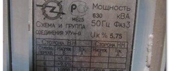
The letter designation indicates the rated power, kVA; winding voltage class (VN); climatic modification and placement category according to GOST 15150-69 and GOST 15543-70.
For example, TDTN-16000/110-U1 is a three-phase transformer with a cooling system D, three-winding, with voltage regulation under load, rated power 16000 kVA, HV voltage 110 kV; climatic version U (moderate climate); accommodation category 1 (outdoors).
AIR COOLING SYSTEM OF POWER TRANSFORMER
Natural cooling of transformer equipment with air is carried out by its convection and incomplete transfer of thermal energy to the surrounding atmosphere. Such transformers are called “dry” and have several types of casing with their own markings:
- open (C),
- protected (SZ),
- sealed (SG).
In addition to natural air cooling, a forced cooling system for dry-type transformers is also possible.
This technology works by blowing air with fans and is designated SD. Such devices are installed in residential and industrial premises where the use of oil samples is prohibited due to the flammability of the coolant.
The thermal resistance class of the insulation directly affects the permissible difference between the temperature of the transformer winding and the temperature of the surrounding cooler. This value is established by GOST 11677-85 and corresponds to the following table:
| Heat resistance class | Excess temperature |
| A | 60oC |
| IN | 75oC |
| WITH | 80oC |
| F | 100oC |
| H | 125oC |
The air cooling system of a power transformer is ineffective and is used for transformer equipment of low and medium power - up to 1600 kVA*A at a rated voltage of up to 15 kV, as well as at constant low temperatures or at temporary sites.
However, to create insulation with increased heat resistance, organosilicon (epoxy) compounds are increasingly being used. This technology makes it possible to produce dry power transformers with a rated power of up to 15 MV*A at the same voltage.
With appropriate justification, such equipment can be operated at power plants.
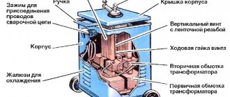
Features of the design of the cooling system for oil transformers
Oil is used in transformers not only as a cooling medium, but also as a liquid dielectric. The windings are made in such a way that in the housing between them there are free cavities filled with a dielectric liquid.
Heat is dissipated through tubes with an elliptical cross-section, located on the outer sides of the housing. The coolant circulates in a circular pattern, from the tank to the tubes, through the expander, and back again.
For transformers of a class of 5 MVA or more, this is not enough, and it becomes necessary to install radiators for additional heat removal from the magnetic core and windings.
Power transformer: classification, features, manufacturers
A power transformer is a specialized electromagnetic static converter of electrical energy that converts alternating voltage of one magnitude into alternating voltage of another magnitude through electromagnetic phenomena, which ensures galvanic isolation between electrical circuits of different networks. The main areas where electrical installations of this type are used are:
- Electricity distribution companies;
- Electricity generation enterprises: nuclear power plants, thermal power plants, hydroelectric power plants, combined heat and power plants;
- Enterprises for the extraction of oil, gas and other minerals;
- Railway infrastructure facilities;
- Enterprises of housing and communal services, social sphere, urban infrastructure;
- Industrial enterprises, factories, plants and factories.
Classification
All power transformers are divided into a large number of different types and modifications depending on their design features:
- Number of windings: two-winding, three-winding, multi-winding;
- Number of phases: single-phase and three-phase;
- Winding connection diagram: triangle, star, zigzag;
- Winding connection group;
- Main purpose: increasing and decreasing;
- Type of main winding insulation: oil and dry;
- Climatic version: for outdoor or indoor use;
- Possibility of regulating the output voltage: unregulated, adjustable (on-load tap-changer and tap-changer);
- Material for making windings: copper or aluminum;
- Magnetic core design: rod or armored;
- Type of cooling system: natural or forced;
- Dimensions.
Design features
The design of power transformers includes a large number of different elements, which are divided into two groups: main and auxiliary. The group of main structural elements of a transformer includes:
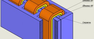
- Magnetic core. Designed for the passage of magnetic flux, which is excited in the windings. It is made from electrical laminated steel or amorphous materials. Structurally, it consists of rods on which windings and a yoke are placed, designed to combine all elements into one system;
- Windings They are a set of turns of a conductor that form a common electrical circuit. The winding is designed to induce EMF, which are summed up and form an electromagnetic flux. The windings of power transformers are distinguished by the material of manufacture, the relative position on the magnetic core, the method and direction of winding, the number of turns, the pattern of connecting the windings to each other, and the voltage class;
- Frame. Designed for fastening and placing all main and auxiliary structural elements. The body is made of durable steel with mandatory corrosion protection. For the safety of operating personnel, the power transformer housing must be grounded;
- High voltage bushings. They are an insulating structure that ensures the connection of the transformer windings to the electrical network by safely passing through a grounded metal casing. The design and type of high-voltage bushing depends on the network voltage class, rated current, and climatic operating conditions of the transformer;
- Extender. A special vessel that is connected to the oil power transformer tank in order to compensate for changes in the volume of transformer oil when its temperature changes. The second important function of the expander is to reduce the area of contact between transformer oil and air, which provides protection against oxidation, moisture and premature aging;
- Insulation. Provides insulation of current-carrying parts from grounded parts of the transformer, as well as between windings of different types. Depending on the type of transformer, the insulation may be transformer oil or solid compound;
- Output voltage regulation device. Designed to change the output voltage of a power transformer. Depending on the design, it is performed in two different versions: on-load tap-changer (voltage regulation) and off-load switching (non-excited switching);
- Cooling system. Ensures long-term trouble-free operation of the power transformer at a given temperature. For low-power transformers it is performed in the form of natural cooling with ambient air. For high-power transformers, this is done forcibly by circulating air, oil or water.
The group of auxiliary structural components of a power transformer includes:
- Gas relay. It is a device that is sensitive to the concentration of gas released during the decomposition of transformer oil inside the power transformer tank. Depending on the settings, the gas relay gives a warning signal or turns off the power to the power transformer;
- Temperature indicators. Special sensors built on the principle of a thermocouple that constantly measure the temperature of the upper layers of insulation in a power transformer;
- Moisture absorbers. They are a mandatory component for power oil transformers. They ensure the removal of moisture from the air that enters the power transformer and comes into contact with the transformer oil;
- Oil level indicator. A device that provides control over the level of transformer oil inside the tank. When the oil level drops critically, the device gives a warning signal or disconnects the transformer from the supply network;
- Oil regeneration system (thermosyphon filter). It is an effective way to clean transformer oil without removing the load from the electrical installation. Coarse-grained adsorbent (silica gel) is used as filter materials. Oil circulation through the thermosyphon filter is carried out due to the difference in temperature and, accordingly, density in the lower and upper parts of the transformer.
Marking
In accordance with the requirements of international standards, the marking of a power transformer is carried out as follows:
Letter part of the type designation:
E – electric furnace. L – linear. A – autotransformer. absence of designation – transformer.
Number of phases:
O – single-phase. T – three-phase.
Type of cooling system:
- Oil transformers: M, MV, D, MC, NMC, DC, NDC, C, NC.
- Dry transformers: S, SG, SD, SZ.
Manufacturers
The most famous manufacturers of power transformers in the Russian Federation and CIS countries are:
- Kentau Transformer Plant, Kentau, Republic of Kazakhstan;
- Togliatti transformer, Tolyatti;
- Samara Electroshield Samara;
- Minsk Electrotechnical Plant, Minsk, Republic of Belarus;
- GC "SVEL" Ekaterinburg;
- Ural Transformer Plant, Uralsk, Republic of Kazakhstan.
Design and operating principle
Design of a dry transformer
The design of a dry unit is practically no different from a classic oil transformer.
Among the elements of air-cooled power transformers are:
- Magnetic core is an element for transmitting magnetomotive force between windings. Most often it is made of laminated, strip or plate steel. By design, the cores of dry-type transformers can be rod-shaped, ring-shaped or armored.
Rice. 2. Magnetic core of the transformer
- Windings are an element for the flow of electric current and the formation of electromagnetic interaction, the subsequent generation of EMF and MMF. Copper or aluminum conductors of round or rectangular cross-section are used to make windings. As in power oil transformers, high-voltage windings are placed on low-voltage windings, and in low-power ones they can be spread across the poles of the core.
Rice. 3. Dry transformer windings
- Winding insulation - used for electrical separation of live parts from grounded parts, protecting them from environmental influences. Cast insulation is produced using electrical varnish, polyamide and epoxy resins, and can be coated with polymer compounds, impregnated fabric, and others. Most materials contain fire retardants - substances that lead to self-extinguishing upon fire.
- Connecting ties, bolts, frames, spacers and other auxiliary parts that ensure reliable fastening and fixation of all parts. Each specific model may apply all or only some of the above.
- Protective casing or housing - necessary to prevent proximity to live parts at an unacceptable distance. A special casing is made of metal, and during operation it is grounded.
Rice. 4. Dry transformer in housing
- Insulators - necessary for bringing the ends of the high and low voltage windings through the housing.
The principle of operation is to apply voltage to the primary winding of a dry transformer, after which electric current begins to flow through it. From the directed movement of charged particles, an electromagnetic flux arises, inducing an EMF in the secondary winding. Which provides the potential difference in the secondary winding and the ability for current to flow when the rated load is connected.
There are three types of windings in dry units - open, monolithic and cast. Due to the use of monolithic and cast windings, transformers of this series dissipate heat much worse, so they use conductors of larger cross-sections. And during operation, the removal of thermal energy may require forced air supply or more space in the housing, the presence of additional ventilation ducts to remove air masses.
Rice. 5. Transformer ventilation system
Which option should you prefer?
There is no single answer to this question, since there are many factors that determine the decision. As practice shows, transformers of the NDC and NMC types are used on the modern market, which are accompanied by natural circulation of oil and forced air supply. Such products have increased resistance to temperature changes and create a protective film that prolongs the life of the equipment.
At the same time, there are more advanced and safer technologies that help avoid force majeure situations. For example, fires at substations, when all outdoor switchgear equipment burns out completely. It is necessary to move forward towards technological progress, but also not to forget about the developments of past years. After all, you will have to work with old equipment for a very long time.
Sources
- https://RadioLisky.ru/sovety-novichkam/tipy-ohlazhdeniya-transformatorov.html
- https://kaksvet.ru/osnovy/sistemy-ohlazhdeniya-maslyanyh-transformatorov.html
- https://CrystalSoap.ru/novosti/tipy-ohlazhdeniya-transformatorov.html
- https://pairon.technology/a221745-vidy-ohlazhdeniya-silovyh.html
- https://int43.ru/novosti/vidy-ohlazhdeniya-transformatorov.html
- https://svet-komfort.ru/shkola-elektrika/tipy-ohlazhdeniya-transformatorov.html