Are you satisfied with the reliability of your old household appliances, but have to turn them on and off yourself? Devices can be updated and improved by setting a timer for turning electrical appliances on and off yourself. The modernization process is not complicated, but it requires precision and attention.
- Operating principle and applications
- The need for a turn-on timer for electrical appliances
- A few words about varieties
- Types of relays
- Transistor timing device
- Relay on a chip
- Device for switching 220 volt equipment
- We create a time relay for 12 and 220 volts
- Manufacturing with diodes
- Using transistors
- Chip-based creation
- Using ne555 timer
- Multifunction devices
- Practical schemes
Operating principle and applications
The operation of auto timers is based on the principle of closing and opening the electrical network, based on the established parameters. After pressing the button, the equipment or lighting is turned on and the countdown in the controller begins. After the set period has expired, the time relay is triggered, the current supply is stopped and the equipment is turned off.
The mechanism for activating the devices is different, but in any relay, after the set period has expired, the operating mechanism is turned off.
Timing relays use:
- in washing machines;
- in kitchen devices - microwaves, ovens, ovens;
- in ventilation and irrigation systems;
- in lighting fixtures.
The timer is actively used for resistance welding in everyday life, in production, and in some schools (bells for lessons and breaks).
Switching principle
The closure of the contacts of the power circuit is carried out by a contactor - a device in which a group of contact plates coupled to the armature of an electromagnetic relay is closed to fixed contacts connected to the input and output terminals for connecting the supply voltage of the network and load lines.
Thus, with the help of low currents in the electromagnetic relay coil and low-current control signals, it is possible to switch high-current circuits of large loads. The small current and low voltage of the signal circuit makes the operator’s work much safer, and for automatic monitoring and control systems it gives a wide scope for their use, thanks to the introduction of computerized algorithms into the process.
Trigger parameters
For a variety of purposes, the following series of magnetic starters are produced: PA, PM, PMA, PME, PML. Based on the load parameters, the selection and use of these devices is carried out according to compliance.
PML series magnetic starter
1. The value of the electromagnetic starter is a conventional term that characterizes the permissible continuous currents of the contacts of the main power circuit. At the moment, there are the following numerical designations of quantities and the corresponding rated currents at a voltage of 380V in the AC-3 operating mode:
- “0” - 6.3 A;
- “1” – 10 A;
- “2” - 25 A;
- “3” - 40 A;
- “4” - 63 A;
- "5" - 100 A;
- “6” - 160 A;
- "7" - 250 A.
2. Operating mode of the starting device, which determines the nature of the switched load:
- AC-1, only active load, or low inductive load;
- AC-3, starting the electric motor and turning it off during rotation;
- AS-4, difficult starting of the engine, turning it off at low speeds and with a stationary rotor, countercurrent braking.
3. Operating (switching) voltage of the relay coil, which can have the following values:
- Variable: 24; 36; 42; 110; 220; 380 V.
- Constant: 24V.
4.The number of additional contacts having this designation in Latin letters and Cyrillic letters:
- Normally open (NO), (NO);
- Normally closed (NC), (NC).
A few words about varieties
Time relays are classified as devices:
- mechanical type;
- with an electronic operating mechanism (including thyristor);
- pneumatic relays.
By design, electrical devices are relay (the most reliable and popular), semi- and thyristor. The location of the connecting element is:
- rear;
- front;
- lateral;
- via a separate connector.
The timing parameters are set using buttons, a switch, or a potentiometer.
Types of relays
The most popular are electronic mechanisms for turning on equipment. But pneumatic and clock timers (that is, mechanical) are no less effective.
The basis of pneumatics is a damping device. By expanding or narrowing the pipe supplying air, the response time is adjusted. The tube diameter is adjusted using a screw. The mechanism is simple and easy to assemble yourself from available materials. The disadvantage is that there are time delays. Such a device is installed on equipment where time control does not require special accuracy.
Transistor timing device
The simplest circuit is based on transistors and is used in lighting devices. The elements are connected by soldering, without using a board. To turn on, press the button, after a set time interval the light goes out.
The disadvantage of this type of relay is false alarms; the capacitor must be discharged before the next turn on, and it is difficult to accurately set the time in the device.
Relay on a chip
A more accurate mechanism for controlling time and turning on/off electrical appliances is on microcircuits. Such devices are used if the timer operates at long intervals, within 10 - 60 minutes. When using microcircuits, false switching on/off is eliminated, and current control is more reliable.
Advantages of electronic devices:
- small sizes;
- large selection of programs;
- low power consumption;
- all elements are stationary;
- long service life.
The disadvantage of such schemes is more complex installation, high cost of parts, and therefore of the controller.
Timer with extended time interval
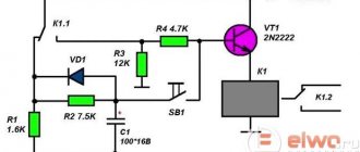
A diagram of a device for a similar purpose is shown in Fig. 2. It allows you to discretely change the load shutdown delay time from 5 to 30 minutes (in steps of 5 minutes) using switch SA1. Thanks to the use of a micro-power timer with a high input resistance, it is possible to use timing resistors of significantly larger values (from 8.2 to 49.2 MOhm), which allows the time interval to be increased: T = 1.1 * C2 * (R1 + ... + Rn).
Rice. 2. Timer circuit with an increased time interval to disconnect the load.
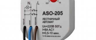
Device for switching 220 volt equipment
Clock options are used by electricians. The basis of the device is a spring, which is charged by an electromagnetic mechanical drive. Time intervals are set on a special scale. After the end of the set period, the contact groups of the clock device are switched.
This type of time relay is installed on automatic switches of electrical circuits. The advantage of clock timers is complete autonomy.
How to distinguish normally closed from normally open contacts?
On PME starters they are open and visible. But we will show, using the example of a PML starter, how to do this in the case when the contacts are closed.
The multimeter is set to continuity mode, and no voltage is supplied to the starter. This is his normal state. Then the contact groups are called one by one. Those that do not ring are normally open, and those that, on the contrary, ring are normally closed.
You will be interested in: Alternative electricity: methods of generating energy, necessary equipment
We create a time relay for 12 and 220 volts
Transistor and microcircuit timers operate at a voltage of 12 volts. For use with 220 volt loads, diode devices with a magnetic starter are installed.
If you plan to install a time relay on low-power equipment, do not install a magnetic starter. The diode bridge and thyristor convert the voltage without it.
To assemble a controller with a 220 volt output, stock up on:
- three resistances;
- four diodes (current more than 1 A and reverse voltage 400 V);
- capacitor with an indicator of 0.47 mF;
- thyristor;
- start button.
After pressing the button, the network closes and the capacitor begins to charge. The thyristor, which was open during charging, closes after charging the capacitor. As a result, the current supply stops and the equipment turns off. The correction is carried out by choosing the resistance R3 and the power of the capacitor.
Manufacturing with diodes
To install a diode system, the necessary elements are:
- 3 resistors;
- 2 diodes rated for current 1 A;
- thyristor VT 151;
- starting device.
The switch and one contact of the diode bridge are connected to a 220 volt power supply. The second wire of the bridge is connected to the switch. The thyristor is connected to resistances of 200 and 1,500 Ohms and a diode. The second terminals of the diode and the 200th resistor are connected to the capacitor. A 4300 Ohm resistance is connected in parallel with the capacitor.
Using transistors
To assemble a circuit using transistors, you need to stock up on:
- capacitor;
- 2 transistors;
- three resistors (nominal 100 kOhm K1 and 2 models R2, R3);
- button.
After turning on the button, the capacitor is charged through resistors r2 and r3 and the emitter of the transistor. At the same time, the voltage across the resistance drops as the transistor opens. After the second transistor opens, the relay is activated.
As the capacitance is charged, the current drops, and with it the voltage across the resistance to the point at which the transistor closes and the relay is released. For a new start, the capacity must be completely discharged; this is done by pressing a button.
Chip-based creation
To create a system based on microcircuits you will need:
- 3 resistors;
- diode;
- TL431 chip;
- button;
- containers.
The relay contact is connected in parallel to the button to which the “+” of the power source is connected. The second relay contact is connected to a 100 Ohm resistor. The resistor is also connected to resistances.
The second and third pins of the microcircuit are connected to a 510 Ohm resistor and a diode, respectively. The last contact of the relay is also connected to the semiconductor, with the execution device. “–” of the power supply is connected to a 510 Ohm resistance.
Using ne555 timer
The simplest circuit to implement is the NE555 integrated timer, so this option is used in many electrical circuits. To install the time controller you will need:
- board 35x65;
- Sprint Layout program file;
- resistor;
- screw terminal blocks;
- spot soldering iron;
- transistor;
- diode.
The circuit is mounted on the board, the resistor is located on its surface or brought out by wires. The board has space for screw terminal blocks. After soldering the components, excess solder is removed and the contacts are checked. To protect the transistor, a diode is mounted in parallel with the relay. The device sets the response time. If you connect a relay to the output, you can adjust the load.
Operating principle of the system:
- the user presses a button;
- the circuit closes and voltage appears;
- The light comes on and the time countdown begins;
- After the set period has expired, the light goes out and the voltage becomes 0.
The user can adjust the operating interval of the clock mechanism within 0 - 4 minutes, with a capacitor - 10 minutes. The transistors used in the circuit are bipolar devices of low and medium power of the npn type. The delay depends on the resistances and capacitor.
Multifunction devices
Multifunctional time controllers perform:
- counting down time in two versions simultaneously during one period;
- parallel counting of time periods continuously;
- countdown;
- stopwatch function;
- 2 autostart options (the first option after pressing the start button, the second – after applying current and expiration of the set period).
To operate the device, a memory block is installed in it, in which settings and subsequent changes are saved.
Schemes for connecting the device to the electrical circuits of the equipment:
Operating mode 1 - three-pin switching circuit
Operating mode 2 - two-contact switching circuit. This operating mode uses only one total operating time counter and records the number of equipment starts.
To connect the meter to the power supply circuits and external sensors, standard blade contacts (modification SVN "DonKont-1") or lead conductors (modifications SVN "DonKont-2" and SVN "DonKont-3" are used)
“SVN-DonKont” meters are microprocessor devices and can be programmed in accordance with the consumer’s technical specifications upon additional agreement.
Connection diagram for the DonKont-3 modification of the SVN