Today, many new manufacturers of electrical contacts for various electrical equipment have appeared on the Russian electrical market. Not all of these enterprises produce contact units in strict accordance with the design documentation established for them. The overall dimensions of copper, brass and silver contacts, as well as the technology for their production in production, for the most part do not correspond to those established in the specifications of the manufacturers. Many products for contactors and various magnetic starters are made from some sheet copper, ignoring the technical documentation of the starter manufacturers' factories. In addition, the strength of welded or various soldered joints is not ensured. Electrical contacts from such manufacturers have a significantly shorter service life in terms of switching wear resistance. The use of products of this quality can lead to a variety of unforeseen emergency situations: separation of contact parts, welding of copper and silver contacts during switching, overheating and, of course, too rapid wear, and naturally to breakdown of both the starter or contactor itself and the device itself. in which it was installed.
The products supplied by our company are manufactured in full compliance with design technical documentation, specially developed by factories that produced electromagnetic starters, contactors and controllers. All fixed and moving contacts are manufactured using powder metallurgy technology.
Basic Concepts
The word contact means contact, contact. Two parts designed to conduct current and in contact are usually called contact parts or, in short, contacts. In the contacts to be considered, electrical conductivity is usually achieved by the presence of pressure on the contact parts, generated by screws or springs.
In the electrical system - machines, devices, lines, etc. there are a huge number of contacts. The quality of contacts has a direct bearing on the reliability of electrical equipment. Poor quality contacts are often the source of damage and disruption to the normal operation of the installation.
According to their purpose and operating conditions, the contacts considered here can be divided into two main groups - non-opening and openable.
Non-opening contacts, in turn, are divided into:
- fixed contacts in which there is no movement of the contact parts relative to each other, for example, screw connections of busbars, wires, connections to devices;
- movable contacts in which sliding or rolling of one contact part relative to the other takes place; Such contacts (along with openable ones) are available in disconnectors and switches.
Contacts can also be classified according to the type of contacting surfaces. There are flat, linear and point contacts. Flat contact is formed when flat contact parts, such as flat bars, come into contact. Linear contact can be formed by two cylinders with parallel axes or a cylinder and a plane. Point contact can be formed by two spherical surfaces or two cylinders crossed at right angles. The concepts of flat, linear and point contacts are arbitrary, since they assume the presence of ideal surfaces. In reality, contact between the contact parts in all cases occurs over small areas.
The surface of a solid cannot be perfectly flat. With the most careful processing there is some waviness and roughness. If the contact material were infinitely hard, contact would occur at several points. In reality, under the influence of the applied force, the material deforms and the original points of contact turn into small areas. As the force applied to the contacts increases, the number of contact “points” and their total area increases.
The pressure is distributed unevenly across the site. In this case, the metal is deformed partly plastically, partly elastically. The relationship between the force P applied to the contacts and the contact surface sd, which perceives pressure, has the following form:
P = psd, (1)
where p is the average specific pressure, depending on the curvature of the surface of the contact parts, their waviness, the applied force and the elastic modulus of the material.
The contact surface that perceives pressure is many times smaller than the apparent contact surface sk, which is easy to measure.
On the surface of the metal there is usually a thin foreign layer of greater or lesser thickness that prevents direct contact of the metal contacts. This layer consists of adsorbed gases and fats. oxides, etc. It is extremely difficult to obtain truly clean contacts. To do this, they must be cleaned mechanically and then subjected to prolonged heating in a vacuum. With this treatment, the surface layer, including oxides, is decomposed and the contacts become clean. However, water, as well as oxygen and other gases, immediately precipitate on clean metal contacts in the air. When the contacts are closed, part of this sediment is squeezed out. A molecular layer (film) remains on the surface, capable of withstanding significant pressure. This thin layer (up to 30 A (A - angstrom; 1 A = 10-8 cm)), which prevents the contact of metals, does not disrupt conductivity. The passage of current is explained by the tunneling effect - the ability of electrons to overcome a potential barrier if the layer thickness is small (similar to the passage of light through a thin metal sheet). The resistance of a thin film of adsorbed gases is relatively low.
When contacts are exposed to air for a long time, a relatively thick foreign layer is formed on their surface, consisting of oxides, sulfites, chlorides and other compounds. The rate of formation of a foreign layer depends on temperature, air humidity and the presence of chemical agents. Noble metals, such as silver, are also susceptible to oxidation, but the oxidation process is slower, the layer is less durable and easily decomposes when heated.
The oxide layer is practically non-conductive. However, under pressure it can be partially destroyed, since the metal is capable of deforming plastically while maintaining adhesion; the oxide layer cannot follow this deformation due to brittleness. Therefore, when pressure is applied to the contacts, the foreign layer breaks off and cracks appear into which the metal penetrates, forming conductive contact points. As the pressure increases, the number of contact points and the conducting surface sp increase. In the presence of sliding between the contacts, the formation of cracks is facilitated, since tangential stresses appear and shearing occurs. The thicker the foreign layer, the more difficult it is for metal to penetrate into cracks.
From the above it follows that the contact surface that perceives pressure consists of sections:
- 1) with metal contact;
- 2) covered with a thin film that does not represent significant resistance to current;
- 3) coated with oxides that practically do not conduct current.
Fig.1. Surface of flat contact: sk—apparent surface; sd is the pressure-receiving surface; sp - conductive surface
Figure 1 schematically shows the surfaces: apparent, pressure-receptive and conductive in relation to flat contacts. In general, sk > sд > sp. In some cases sk = sd = sp. In some cases it is impossible to distinguish between these surfaces.
Sparking on contacts and electric arc
At significant voltages and currents, when the electrical circuit is opened, an electrical discharge is formed between diverging contacts. At the same time, in the contact area, when the contacts diverge, there is a sharp increase in the transition resistance and heating of the contacts until they melt and form a contact isthmus of molten metal.
As a result of high temperatures, contacts can heat up and tear, while the metal of the contacts evaporates, and an ionizing conductive air gap is formed between the contacts, in which, under the influence of high voltage, an electric arc occurs, which reduces the speed of the switching device and contributes to further destruction of the contacts.
To stop the arc from occurring, you need to increase the resistance in the circuit by increasing the distance between the contacts, or use special measures to extinguish it.
The breaking or switching power of contacts is the product of the limiting values of current and voltage in the circuit, at which an electric arc does not form at the minimum distance between the contacts.
The electric arc goes out when the instantaneous current value in alternating current circuits reaches zero and may reappear if the voltage on the contacts increases faster than the electrical strength of the gap between the contacts is restored.
In any case, in an alternating current circuit the arc is unstable, and the breaking power of the contacts is several times higher than in a direct current circuit.
In low-power electrical devices, an electric arc rarely appears on the contacts, but sparking or breakdown of the insulating gap, which is dangerous for sensitive devices, very often occurs. A breakdown occurs in low-current circuits during rapid opening of contacts and can lead to false trips and significantly reduce the service life of contacts. In order to reduce sparking, spark extinguishing devices are used.
Another interesting video about electrical contacts:
Contact resistance
The concept of contact resistance needs clarification. The name itself shows that we are talking about the resistance of the boundary (contact) layer. However, this is not quite true. You can thoroughly clean the contacts, remove a layer of foreign substances, and still the contact will have resistance due to the limited number and small size of contact points. The current lines in the body of the contact parts deviate from the direction they would have if the entire apparent contact surface were conductive, which leads to an increase in resistance. This additional resistance of the contact body in the region of narrowing of the current lines, and not the boundary layer, is called the narrowing or contraction resistance. It constitutes the main part of the contact resistance, since the resistance of a thin film of adsorbed gases is negligible. Thus, the contact resistance consists of two parts - the contraction resistance Rс and the film resistance Rpl:
R = Rс + Rpl (2)
Expression (2) is also valid for oxidized contacts, although their resistance is much greater due to the smaller number and smaller size of contact points.
Fig.2. Schemes explaining the concept of constriction resistance: a - streamlines and equipotential surfaces in cylindrical contacts with one point of contact; b - the same in a solid rod with the same dimensions
Let us explain the concept of contact narrowing resistance using the example of contacts in the form of cylindrical rods made of the same material, their ends touching. Let us assume that the contacts have only one contact “point” in the form of a round area located in the center of the apparent contact surface and free from a foreign layer. In this case, the streamlines and equipotential surfaces have the form shown in Fig. 2,a. The resistance between two equipotential surfaces sufficiently distant from the contact pad, for example between points m and n, is equal to
Rmn = U/I
Now let’s imagine a cylindrical rod made of the same material and with the same dimensions as contacts A1 and A2 taken together (Fig. 2b). Such a rod differs from the contacts A1 and A2 in contact only in the absence of a joint. The streamlines here are not curved. Let the resistance of the rod between points m and n be equal to R'mn. Then the narrowing resistance of contacts A1 and A2 will be:
Rc = Rmn - R'mn
In the region of narrowing current lines, the voltage gradient is relatively large, and beyond it is small. Consequently, R'mn is small compared to Rmn and there is no need to accurately determine the points m and n between which the voltage is measured. Moreover, the resistance R'mn can be neglected and the contact narrowing resistance can be defined as the resistance between two points located in areas with a relatively small voltage gradient.
Fig.3. Diagram of a semi-infinite contact with a flat contact point
Analytical determination of constriction resistance presents significant difficulties even for contacts of the simplest shape, since the electric field in conductors with limited dimensions is complex. The problem can be solved for a point contact if we assume that the contact pad is round with radius a and the dimensions of the contacts are large compared to the dimensions of the contact pad. In this case, the equipotential surfaces are ellipsoids (Fig. 3). The current density is not the same on the contact pad: it increases sharply at the edges (the numbers next to the current lines indicate the fraction of the current that passes through the space limited by the surface formed by this line when it rotates around the axis of the contacts). The expression for the narrowing resistance in the scheme under consideration has the following form:
Rс = р/(2а) (3)
Thus, the contraction resistance Rc depends on the resistivity of the contact material p and the linear dimensions of the contact pad. The size a is included in (3) to the first power, which should not raise doubts. Indeed, most of the contraction resistance is associated with the relatively small volume adjacent to the contact pad. The base area of this volume is proportional to a2, and the height is approximately equal to a. Consequently, the resistance of the volume under consideration is proportional to a/a2 = 1/a.
The resistance of a multipoint contact in the presence of n contact points with radius a, evenly spaced at a sufficient distance from each other, is equal to:
Rc = р/(2аn) (4)
As the number of contact points increases, the contraction resistance tends to zero, despite the fact that the surface of each point also tends to zero.
Dependence of contact resistance on pressure. As the force applied to the contact parts increases, the contact resistance decreases. This is due to the increase in the number of contact points and the total conductive surface. The dependence of the contact resistance on the applied force is complex and can be found only for a special case - a point contact formed by a sphere and a plane or two cylinders with the same radii. Under the action of a force P directed along a straight line connecting the centers of curvature, the initial point contact will turn into a contact along a circular area with radius a.
The pressure is distributed unevenly over the contact area: the highest pressure occurs in the center of the area, where it is 1.5 times greater than the average pressure; at the edges of the site the pressure is zero. As the force P increases, the pressure on the contact pad increases, and when the latter reaches a value corresponding to the hardness of the material, plastic deformation will begin, first in the center of the pad, and with a further increase in pressure - throughout the pad. If the force is sufficiently large, it can be assumed that the pressure over the entire area is the same and equal to the hardness of the contact material, i.e.
Р = σтπа2 (5)
where σ is the Brinell hardness of the contact material.
From expression (5) it is clear that the radius of the contact area at high pressure and plastic deformation is proportional to the square root of the force P. Therefore, the contact resistance according to (3) is proportional to the pressure force to the power of -1/2:
Rc = P-1/2
at low pressure and elastic deformation, the contact resistance is proportional to the pressure force to the power of -1/3 i.e.
Rc = P-1/3
These expressions are in good agreement with the experimental results if the contacts are clean.
The dependence of the resistance of linear and flat contacts on pressure cannot be represented analytically, since the number and dimensions of contact points are unknown. Experience has established that the resistance of a flat contact depends on the resistivity and hardness of the metal, surface treatment and the force applied to the contact parts. It is important that the contact resistance does not depend on the apparent contact surface.
The advantage of point and linear contacts is that their conductivity is satisfactory with a relatively small applied force. This is essential for switching device contacts, where the force determines the required drive power. Flat contacts are widely used in non-opening fixed connections where forces can be very large.
Resistance of oxidized contacts
As stated above, the oxide layer formed on the contact surface is non-conductive. Despite this, the conductivity of oxidized contacts may turn out to be satisfactory due to: 1) partial mechanical destruction of the oxide layer, as mentioned earlier, or 2) its electrical breakdown.
Experiments carried out with outdoor disconnectors with point contacts have shown that the thick foreign layer is not destroyed when the disconnector is turned on. When switched on, electrical breakdown of the foreign layer occurs and an arc discharge occurs. Molten metal penetrates into the resulting thin channels. Conductive filaments are formed, the diameter of which is estimated at approximately 400 A.
The described phenomenon was observed on contacts made of any metals and with any layer composition. The breakdown voltage depends on the melting temperature of the metal and the thickness of the layer. If the latter is small, then the critical voltage is only a few volts. However, with a large layer thickness it can reach several hundred volts. In installations with voltages above 1000 V, the formation of electrical contact occurs precisely in this way.
Electrical resistance of moving and fixed switching contacts
A very important characteristic that determines the performance of brass, silver, copper and nickel-plated contacts is their electrical resistance. It is usually determined by the transition resistance, which directly depends on the contact area. In order to reduce the contact resistance, it is necessary to increase the pressing force of the fixed and moving switching contacts. The appearance of current in the electrical circuit of the contacts necessarily entails their heating, which is proportional to the transition resistance. The more the switching contacts heat up, the more the contact resistance increases, which contributes to even greater heating. The established operating temperatures of such electrical contacts are within the range of 100°C-120°C. Therefore, as the rated current of any switching device increases, the contact resistance of brass, silver-plated or copper contacts must certainly be reduced, that is, the contact pressure must be increased. In addition, with an increase in switched current, it is necessary to increase the cooling surface, that is, the size of all contacting surfaces. Basically, current-carrying contact elements are made from materials with low electrical resistivity (for example: silver, copper, metal-ceramic compositions).
Heating of contacts
When current passes through a contact, the highest temperature occurs on the contact surface. As you move away from this surface deeper into the body, the contact temperature quickly decreases. It is not possible to measure the temperature of the contact surface (for example, using a thermocouple). However, it can be determined indirectly by measuring the voltage drop across the contact.
The relationship between the voltage U and the excess of the temperature θ of the contact surface over the temperature at points remote from this surface in a steady state can be found based on the analogy between electric and thermal fields. This dependence, which is quite complex when all factors are taken into account, can be easily found if the electrical resistivity and thermal conductivity of the contact material are assumed to be constant, i.e. independent of temperature. Contacts are assumed to be clean. Therefore, there is no resistance between the contact surfaces. Such contacts can be considered to consist of a whole piece of metal.
The heat generated in the area of narrowing of current lines spreads from the contact surface into the body of the contacts. Due to the complete symmetry of the contact parts, there is no heat exchange between them. The heat transfer into the thin layer of air between the contacts is negligible. Under these assumptions, the relationship between the voltage U and the excess of the temperature of the contact surface θ over the temperature at points remote from this surface has the following form:
(6)
where p and λ are, respectively, the electrical resistivity and thermal conductivity of the contact material, which are assumed to be constant.
A more precise relationship between U and θ, taking into account the dependence of p and λ on temperature, has the following form:
(7)
Expressions (6) and (7), valid for contacts with any surface shape, are of great practical importance, since they make it possible to determine the maximum temperature in the contact and judge the quality of the contact by the value of the voltage drop in it. Below are the values of U and θ, calculated using (7) and valid for contacts made of any metals, since the product pλ is approximately the same for all metals:
U, V …….. 0.03 … 0.12 … 0.30 … 0.43
θ,°С …….. 16 ….. 180 …. 700…. 1065
For copper contacts, a temperature increase of 180°C corresponds to the beginning of softening of the metal, and a temperature increase of 1065°C corresponds to its melting.
The temperature of the contact parts at points remote from the contact surface is assumed to be 18°C.
Dependence of contact resistance on temperature. The expression for the resistance of a point contact (3) is valid at a negligible current, which is not capable of noticeably heating the contact. If the current is high, the contacts heat up and the contact resistance increases due to an increase in the resistivity of the metal. Let us assume that at a certain current I the temperature of the contact parts at points remote from the contact surface is equal to ʋ. If the temperature in the narrowing area, including on the contact surface, was also equal to ʋ, then the contact resistance Rʋ could be determined from expression (3), setting p to correspond to the temperature ʋ. However, the temperature in the narrowing region differs from ʋ. It increases as it approaches the contact surface and here reaches its maximum value ʋmax. Therefore, the contact resistance at current I differs from its resistance, which the contact would have if the temperature in the entire narrowing region were the same. It can be determined from the approximate expression
(8)
where Rθ is the contact resistance at the contact surface temperature equal to ʋmax = ʋ + θ ; Rʋ—contact resistance assuming the same temperature in the narrowing area equal to ʋ; θ = ʋmax — ʋ — excess of the temperature of the contact surface over the temperature at points remote from it; ɑ is the temperature coefficient of resistivity.
Since resistance Rθ is represented as a function of maximum temperature rise, the multiplier on θ is not ɑ but only 2/3ɑ.
Fig.4. Dependence of contact resistance on temperature rise
Dependence (8) is valid as long as the dimensions of the contact point remain unchanged. If the current is so high that the temperature of the contact surface reaches the softening temperature of the metal, the size of the contact point increases and the contact resistance decreases. This can be seen from the characteristic R(U) (Fig. 4), which determines the relationship between the contact resistance R and the voltage U. Consequently, the temperature rise θ. The characteristic refers to a single point contact formed by crossed copper rods under some pressure. The ABC curve is calculated using equation (8) under the assumption of a constant contact surface. Section AB of this curve can also be obtained from experiment. At point B, corresponding to a temperature exceeding about 180°C, the softening of the metal begins. The contact area increases and the contact resistance decreases (section BD represents the softening decline). After this, the curve rises again (section DE), but the slope of the curve here is less than the slope of the BC curve due to continuing softening. At point E the contact temperature reaches the melting temperature. A further increase in voltage is impossible, since this brings the contact parts closer together, the size of the contact area increases, and the resistance decreases (section EF represents the melting decline). By decreasing the voltage (current), it is possible to obtain a branch FG parallel to the SVA, which proves the constancy of the contact area due to the welding of the contact parts. Melting and welding of open contacts are very dangerous phenomena, since they can cause the device to fail to disconnect the circuit.
Design and purpose of copper, brass, nickel-plated and silver switching contacts
There are 3 types of electrical contacts: sliding contact (connection using a rheostat), permanent contact (connecting two busbars with a bolt) and switching. The form of contacts is as follows:
- linear contacts - with contact along the line and a high degree of pressure. Copper is used to make these contacts;
- machined contacts - usually used for small currents. When using these contacts, little pressure occurs, and to reduce the resistance of electrical contacts, non-oxidizing precious metals are used;
- surface contacts - they are used with a large degree of pressure in order to contact at high currents between two different surfaces.
Almost all electrical brass, silver, nickel-plated and copper contacts also come in movable and fixed types.
During operation, movable brass, silver, nickel-plated and copper contacts close, connecting with each other, or open, disconnecting using an electromechanical or mechanical drive, and at the same time all devices remain firmly connected to each other.
During operation of fixed switching contacts, the current-carrying elements are tightly and securely fastened to each other and do not move anywhere in relation to each other. In order to create a closed electrical circuit, it is necessary to have several contacts. An example of a fixed silver (silver-containing) or copper contact would be a lever contact device, which is designed for high and medium currents, and also in which the material is copper.
A hinge contact is when the stationary and moving parts are suddenly brought together by the varying forces that can be exerted on the lever. It can also serve as an additional example of moving switching contacts.
A sliding contact is a type of moving contact, and, as in any brush-collector device of various electric machines with direct current, any one element moves relative to all other elements.
In addition to the number of movable contacts, we can include magnetically controlled sealed contacts or, as they are usually called, “reed switches”, the simplest example of which is a sealed glass bulb of a very small size, into which two special flat contact springs made of some soft magnetic steel are soldered. If these magnetically controlled sealed contacts (reed switches) are suddenly placed in a magnetic field created by a permanent magnet or winding, their springs will begin to be magnetized and, accordingly, attracted to one another. At this very time, these electrical contacts are closed and, accordingly, the electrical circuit is closed. These contacts, due to their high elastic force of these springs, can only open when the magnetic field is completely excluded. All surfaces of these springs on the contacts are necessarily covered with a thin layer of some precious metal, which has a low electrical resistivity (for example: silver, platinum, gold). Using reed switches, you can make switching in different electrical circuits in the presence of very low current values from 1A to 0.5A. The flask of the reed switch itself is filled with inert gas or evacuated. All elements of the reed switch have a very small mass and a fairly high speed of their contacts from 0.5 ms to 1.0 ms.
Wear resistance is the main property of any reed switches. For certain types of reed switches, the number of switchings per second can reach two thousand, and up to hundreds of millions of operations.
Gersikons are also magnetically controlled hermetic power contacts. This is a type of reed switches that make it possible to make switching inside electrical circuits at electric current values of 60A, 100A or 180A and at voltages of 220V and 440V.
Contact designs
Contacts of electrical machines, devices, conductors must conduct rated (continuous) currents for an unlimited time; in this case, the temperature of the contact parts should not go beyond the established limits (see Table 1). This requirement is ensured by the selection of appropriate materials, the number of contact points and the pressure on the contact parts.
Table 1
Permissible temperatures for insulating materials at the hottest points during normal operation
The contacts must also be resistant during a short circuit, when the amount of heat generated increases sharply and electrodynamic forces reduce the pressure in the contacts. The presence of electrodynamic forces is explained by the narrowing of current lines when approaching the contact point and, as a consequence, the interaction of oppositely directed currents.
Switch contacts must not only conduct rated currents and have sufficient electrodynamic and thermal resistance in the “on” position. They must also withstand the destructive effects of the arc that occurs when the current is switched off, and ensure reliable switching on during a short circuit.
Non-breaking fixed contacts
Fig.5. Connecting flat bars using bolts
These contacts are usually made using bolts (Fig. 5). To ensure reliable contacts, it is necessary to create conditions for the adhesion of the metal. To do this, the contact surfaces must be thoroughly cleaned and the pressure in the contacts must be sufficient to ensure plastic deformation of the metal. Under these conditions, the metal forms a monolithic mass and the contact remains conductive for an unlimited time. If there is no metal adhesion, the contact is unreliable. since over time, due to the fluidity of the contact material (this especially applies to aluminum), the pressure in the contact decreases. This is facilitated by periodic deformations due to temperature changes, as well as vibration. The contact gets the opportunity to “breathe”, i.e. draw in air that comes into contact with a conductive surface. In this case, the metal oxidizes and the contact resistance gradually increases. The adhesion of the metal at the contact points prevents these undesirable phenomena.
In bolted joints, the contact points are concentrated near the bolt holes, where the metal is plastically deformed. The conductivity of the contact is determined by the number of bolts, their diameter and material. The larger the diameter of the bolts and the higher the tensile strength of the material, the greater the contact pressure and the number of contact points (with appropriate tightening of the bolts). The diameter of the bolts is selected depending on the size of the strips, and the number of bolts ranges from 1-6. Steel bolts with a tensile strength of 200-250 MPa are widely used. However, the disadvantage of steel is that its coefficient of linear expansion is less than that of conductive materials. As a result, as the temperature rises, additional stresses arise in the bolts. If the bolts are tightened excessively, residual deformations appear and the pressure in the contact weakens. To increase the reliability of contact connections, spring disc washers and flat washers are installed under the bolts. Spring washers compensate for thermal expansion of materials and maintain the pressure in the bolted joint at the required level.
The length of the overlap of the strips is chosen so that it accommodates the required number of bolts. Typically it is 10 times the thickness of the strip.
The contact surface is processed with a coarse file (grinding is not practical). To reduce metal oxidation, aluminum tires are coated with a layer of Vaseline before processing. After assembling the contact, the seams are covered with asphalt varnish or paint.
Recently, welding has been widely used to connect aluminum busbars in switchgear. Such connections have high mechanical strength and good conductivity. However, for tires made of hardened aluminum alloys in the weld zone, the material softens and the strength decreases to 50% of the nominal value.
Opening contacts of switches and disconnectors. The designs of these contacts are very diverse - depending on their purpose, rated current and thermal and dynamic resistance currents of the devices.
Fig.6. End contacts of the oil switch: 1 - fixed contact; 2 - moving contact; 3 - contact crossbar; 4 - spring
Figure 6 shows the so-called end contacts of an oil circuit breaker, intended for a rated current of 1000 A, as well as for use as arc extinguishers. They are single point contacts; the pressure in them is created by springs.
For large rated currents, they resort to multipoint contacts formed by a group of copper or brass plates of a special shape, called fingers or plates. They are strengthened on a base (block) and equipped with springs (Fig. 7).
Fig.7. Finger contacts: 1 — block; 2 - fingers; 3 - springs; 4 - moving contact
In the “on” position, the movable contact in the form of a wedge enters the gap between the fingers and is pressed against them by springs. The current transfer from the movable fingers to the block occurs through the protrusions of the fingers a. Flexible connections made of thin copper strips are also used. The number of pairs of fingers is selected in accordance with the rated current. Finger contacts are intended to carry continuous current only. They are used in disconnectors, as well as in switches as main contacts.
Fig.8. Switch socket contact
Figure 8 shows a socket-type multipoint contact intended for switches. The moving contact 1 is made in the form of a round rod. The fixed contact contains 20 plates 2 with springs 3 located around the circumference. The plates are enclosed in a brass cup 4, the upper edge of which protects them from melting by the arc. The current transition from the base of the fixed contact 5 to the movable rod occurs at points m and n.
Note that in finger and socket contacts, the electrodynamic forces that arise in the area of narrowing of current lines and weaken the pressure in the contacts are partially compensated by the interaction of identically directed currents in the fingers and plates.
In many switches, the contact system is divided into main contacts, designed to carry continuous current, and arcing contacts, which take the full brunt of disconnecting the circuit through an arc, as well as switching on a short circuit. Arcing contacts are made of ceramic-metal alloys of tungsten or molybdenum with copper and silver, which have sufficient electrical conductivity and the ability to withstand high arc temperatures. When the switch is turned off, the main contacts open first, then the arc extinguishing contacts. When the switch is turned on, the sequence of contact closures is reversed. To ensure reliable switching on the short circuit, the speed of contact movement (drive power) is increased. The pressure in the contacts also increases. In the “off” position, the contact springs must be partially tensioned so that during the switching process, as the moving contacts move, the pressure quickly increases to a maximum value. The contacts of the disconnectors are not subject to arcing. They are made of copper and brass. To protect against oxidation, the contacts are coated with a thin layer of silver.
Spark and arc extinguishing devices
The most effective way to extinguish an electric arc is to cool it by contact with the insulating walls of special chambers that take away the heat of the arc or by moving it in the air.
In modern devices, arc-extinguishing chambers with a narrow slot and magnetic blast are widely used.
The arc can be considered as a conductor carrying current; if it is placed in a magnetic field, a force will arise that will cause the arc to move. As it moves, the arc is blown with air; falling into a narrow gap between two insulating plates, it is deformed and, due to an increase in pressure in the chamber gap, goes out (Fig. 2.4).
The slot chamber is formed by two walls 1 made of insulating material. The gap between the walls is very small. Coil 4, connected in series with the main contacts 5, excites magnetic flux F, which is directed by ferromagnetic tips 2 into the space between the contacts. As a result of the interaction of the arc and the magnetic field, a force F appears, displacing the arc towards the plates 7.
This design of the arc chute is also used on alternating current, since with a change in the direction of the current, the direction of the flow F changes, and the direction of the force F remains unchanged.
To reduce sparking on low-power DC contacts, a diode is connected in parallel with the load device (Fig. 2.5). In this case, the circuit after switching (after turning off the source) is closed through a diode, thus reducing the sparking energy.
Materials for moving contacts
During operation, materials for moving contacts are subject to electrical erosion, welding, corrosion and mechanical wear. The intensity of erosion, welding and corrosion depends primarily on the nature of the material and the magnitude of the breaking current.
Electrical erosion
– this is the destruction of contact materials (CM), associated with the melting and transfer of metal in gaseous and liquid (in the form of small drops) states from one contacting surface to another under the influence of electrical discharges. Erosion is especially noticeable in direct current circuits, forming growths and craters on contacting surfaces. The higher the values of specific heat capacity, temperature and specific heat of fusion and sublimation temperature of CMs, the lower their erosion.
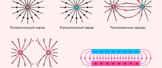
Arcing is characterized by the minimum values of current and voltage at which an arc discharge occurs. As the voltage increases, the minimum arcing current drops almost along a parabolic curve (Fig. 2.10).
Rice. 2.10. Dependence of minimum current I
arcing depending on the operating voltage
U
for various contact pairs
Arcing depends on the nature of the CM and the environment, the state of the contacting surfaces and the inductance of the circuit. Tungsten has the highest minimum arcing current (see Fig. 2.10).
Welding of CM occurs under the influence of high temperatures and contact pressure and can lead to deformation of the contacting surfaces with partial melting or even loss of their ability to open. Therefore, it is very important that CMs have high resistance to welding, which is inherent in tungsten.
Corrosion
– this is the chemical interaction of CM with the environment, as a result of which oxide, sulfide, carbonate and other films with low electrical conductivity are formed on their surface. The thickness of such a film depends on many factors and is usually 10–6–10–5 mm; its electrical resistivity is not less than 103. The current distribution over the contacting surfaces is uneven, since the structure of the surfaces is heterogeneous.
The structure of electrical contact surfaces consists of four main types of contact areas (spots) (Fig. 2.11):
1) contact spots with a metal contact (1), through which electric current flows without noticeable transition resistance;
2) contact spots covered with adhesive and chemisorbed monomolecular films are quasi-metallic contacts (2), easily passing electric current due to the tunnel effect;
3) contact spots covered with electrically insulating, relatively thick films of oxides and sulfides (3) that do not allow electric current to pass through;
4) non-contacting areas (4).
Rice. 2.11 Diagram of the contact surface: 1 – metal spots (areas); 2 – quasi-metallic spots; 3 – spots of insulating thick films of oxides and sulfides; 4 – non-contact areas
The contact of the contacting parts occurs only in areas 1, 2, 3, forming the true contact surface. In areas 4, contact of the contact pair does not occur. The total area of the electrical contact is the sum of the areas of all spots (1+2+3+4) and is the apparent contact surface formed when the roughness protrusions of the contact surfaces are compressed under the action of contact pressure.
The electric current actually passes only through areas (spots) 1 and 2 of the true contact surface. In strong electric fields, as a result of the breakdown of thick films of oxides and sulfides (areas 3) and air layers (areas 4), they also become conductors of electric current. However, in this case, spark and microarc discharges are formed, which intensively destroy the contact surfaces. The condition of the contacting surfaces directly affects the transition (contact) resistance and heating temperature of the contacts when electric current flows through them. Gold Au, platinum Pd and their alloys with iridium Ir, rhodium Rh and some other metals have high corrosion resistance; they have no or very thin oxide films with high electrical conductivity. Contacts made of these metals operate when pressed with a force of 0.15–0.25 N, while for metals with relatively thick oxide films (for example, tungsten) a force of up to 10 N is required to destroy the oxide films upon impact of the contacts.
Mechanical wear occurs as a result of impact of the contact surfaces and subsequent pressure, as well as their friction. To minimize mechanical wear, CMs must have high values of wear resistance, impact strength and hardness. It is better to use noble metals in the form of galvanic coatings, since their wear resistance and hardness are much higher than those of the same metals in solids.
Based on operating conditions, moving contacts are divided into sliding and breaking contacts.
Sliding contacts are needed to transfer electric current from a stationary part of an electrical device to a moving one, for example in rheostats - from the winding to the motor, in electric machines - from brushes to the commutator, in electrified transport - from the contact wire to the current collector. The main disadvantages of these contacts are mechanical wear, the possibility of arcing, as well as electrical erosion and corrosion of the contacting surfaces.
Breaking contacts provide periodic closing and opening of the electrical circuit. For example, in various types of relays, switches, contactors, electromechanical converters. The main difficulties in the operation of these contacts are the possibility of arcing, which causes welding of the contacting surfaces, their electrical erosion and corrosion, as well as mechanical wear.
2.9.1. Materials for sliding contacts
Materials for sliding contacts must have low resistivity and voltage drop across the contacts, high minimum current and arcing voltage, high resistance to abrasion (wear resistance), electrical erosion and corrosion. Sliding contacts, in turn, can be divided into metal and electrical carbon.
Metal sliding contacts include commutator plates of electrical machines, which are made of solid copper, bronze and other materials. In some cases, spring metal contacts are used, mainly used in switches, potentiometers, and rheostats. For the manufacture of spring metal sliding contacts, special grades of bronze are used: cadmium, beryllium and chromium (BrKd1, BrB2, BrKh0.5), which have high elasticity, abrasion resistance and low resistivity. For example, the Cu–Cd alloy (Cd~l%) forms a solid solution that is three times more resistant to abrasion than copper. Brass is also used for the manufacture of sliding contacts (for example, LS 59-1, LMts 58-2). Metal sliding contacts have the highest abrasion resistance when paired with electrical carbon materials.
Electrical carbon materials have relatively high electrical and thermal conductivity, a very low coefficient of friction, high arcing voltage, high chemical resistance, and many of them have high heat resistance. These materials are widely used for the manufacture of carbon electrodes for various applications, brushes for electrical machines and autotransformers, and carbon powders for microphones. Brushes are produced in the following brands: UG (carbon-graphite), G (graphite), EG (electrographite), M and MG (copper-graphite). The specific pressure for all brushes is 20–30 kPa with a friction coefficient for copper of no more than 0.3. The voltage drop at rated current ranges from 0.3 V (MG brushes) to 3 V (EG brushes).
The main raw materials for the production of electric carbon products are natural graphite and carbon black. To obtain a monolithic product, graphite and soot are mixed with a binder - coal tar (a by-product of coking coal) or liquid glass, pressed and fired at a temperature of 2200–2500°C. This process is called graphitization
. As a result of graphitization, the crystallite size increases, electrical conductivity increases and hardness decreases.
Natural graphite is a soft, dark gray crystalline substance that is one of two allotropic forms of carbon; has a layered structure. In the direction of the layers, the electrical conductivity is metallic in nature. For polycrystalline samples, resistivity ρ≈8, TK
ρ= K–1. Individual graphite flakes easily separate and slide over its surface, forming a dry lubricant.
Artificial graphite is known, obtained by thermal recrystallization of coals at a temperature of 2200–2500°C.
Soot is a highly dispersed coal powder (spherical particles reach 10–300 nm); they have a more finely crystalline structure than graphite (they are sometimes called colloidal carbon). The graphite structure in soot is not yet fully formed. Soot is produced by incomplete combustion of many organic substances. Depending on the production method and the raw materials, a number of brands of carbon black are distinguished. The specific resistance of soot in bulk, depending on the calcination temperature and pressure, varies in a wide range from 0.01 to 400.
2.9.2. Materials for breaking contacts
Breaking contacts according to the value of the switched current are divided into low-current
(currents from fractions to units of ampere) and
high-current
(currents from units to thousands of amperes). For the manufacture of low-current breaking contacts, noble and refractory metals are used.
Of the noble metals, silver, gold, platinum and various alloys based on them are used, for example alloys of the systems: gold-silver (Au-Ag), platinum-ruthenium (Pt-Ru), platinum-rhodium (Pt-Rh), silver-cadmium (Ag–Cd), silver-palladium (Ag–Pd), silver-magnesium-nickel (Ag–Mg–Ni). Contacts made of silver and its alloys are used in switching devices operating in arcless mode. Their disadvantage is the possibility of the formation of sulfide films. Gold and platinum in their pure form are used to make precision contacts. Gold is mainly used in the form of alloys with silver Ag, platinum Pt, nickel Ni, zirconium Zr; platinum - in the form of alloys with iridium Ir, nickel Ni, silver Ag and gold Au. These alloys have high hardness and good erosion and corrosion resistance. The advantage of contacts based on gold and platinum is their resistance to the formation of sulfur films, the disadvantage is their tendency to arc.
Refractory metals used include tungsten and molybdenum. The advantage of tungsten is its high resistance to arcing and the virtual absence of weldability. However, tungsten has a relatively thick oxide film, so high contact pressure is required. The disadvantage of molybdenum is the formation of oxide films, which have a loose structure and can suddenly completely disrupt contact conductivity. Tungsten alloyed with molybdenum has increased hardness and resistivity and decreased melting point and corrosion resistance.
Copper, alloys and bimetals based on it are also widely used for the manufacture of breaking contacts.
In the production of high-current breaking contacts, composite materials are widely used, which are a mixture of two phases, one of which provides high electrical and thermal conductivity of the contacts, the other, in the form of refractory inclusions, makes the contacts resistant to mechanical wear, electrical erosion and welding. High-current breaking contacts made of composite materials are produced by powder metallurgy. Compositions based on copper and silver have proven themselves as contact materials: silver–cadmium oxide, silver–copper oxide, copper–graphite, silver–nickel, silver–graphite. Triple compositions are also used: silver–nickel–graphite, silver–tungsten–nickel. In these compositions, copper and silver phases provide electrical and thermal conductivity to the contacts, and inclusions of cadmium oxide and copper oxide, as well as tungsten, nickel and graphite, increase wear and heat resistance and prevent contact welding.
Cu–W, in high-voltage oil switches Cu–Mo, in vacuum chambers Сr–Сu–W, Fe–Сu–Bi have been used as electrical contact compositions in powerful high-voltage oil and air circuit breakers. In order of decreasing resistance to welding, the materials are arranged in the following order: graphite, tungsten, compositions: W–Mo, W–Сu (Ag), tungsten–silver carbide (WC–Ag), Ag–Cd, metal ceramics Ag–CdO (CuO) , Ag (Cu) – graphite, etc.
For the manufacture of high-current breaking contacts operated at elevated voltages and contact pressures, solid copper is also used, which significantly reduces the cost of electrical devices.
2.10. Test questions for chapter 2
2.1. Classify conductor materials according to composition, properties and technical purpose.
2.2. What materials are classified as high conductivity materials, give examples of the most common of them?
2.3. Give the advantages of copper as a conductor material.
2.4. What brands of copper do you know, how do they differ?
2.5. Where is copper used in electrical engineering?
2.6. Describe aluminum. What are its advantages and disadvantages compared to copper?
2.7. What grades of aluminum do you know? Give their differences.
2.8. Where is aluminum oxide film used?
2.9. How do resistivity, specific heat capacity and thermal expansion coefficient depend on temperature for aluminum?
2.10. What materials based on non-ferrous metals do you know?
2.11. What is brass?
2.12. What is the difference between single-phase brass and two-phase brass?
2.13. How are brasses marked? Give examples.
2.14. What is the main distinguishing feature of brass from pure copper?
2.15. Define bronze.
2.16. How are bronzes marked?
2.17. Why are some types of bronzes subjected to heat treatment?
2.18. What aluminum alloys do you know?
2.19. What are the main advantages of aluminum alloys?
2.20. How are aluminum alloys divided depending on ductility and deformability?
2.21. Give the features of duralumin and silumin?
2.22. What are bimetallic conductors, where are they used?
2.23. What is a superconductor called?
2.24. What is the critical temperature for superconductors?
2.25. How does a superconductor behave in a magnetic field?
2.26. What is the basis of the theory of superconductivity created by D. Bardeen, L. Cooper and D. Schrieffer?
2.27. What are Cooper pairs?
2.28. How do electrons in Cooper pairs behave when an electric current is excited in a superconductor?
2.29. What happens to Cooper vapors at temperatures above 0 K?
2.30. What is characteristic of type I superconductors? What materials do they include?
2.31. What are the distinctive features of type II superconductors?
2.32. What are type III superconductors?
2.33. Give the difference between high-temperature superconductors. Where are they used?
2.34. What are cryoconductors? Where are they used?
2.35. What materials are classified as high resistance materials?
2.36. What are metal alloys that form solid solutions used for?
2.37. How are metal alloys that form solid solutions classified according to their intended purpose?
2.38. Define manganin, where is it used?
2.39. What alloy is called constantan?
2.40. What heat-resistant alloys do you know? Describe them.
2.41. What materials are thin resistive metal films made from?
2.42. What alloys are most widely used for making thermocouples?
2.43. How are metals selected for thermocouples?
2.44. What metals are considered refractory?
2.45. Where are refractory metals used?
2.46. Give examples of refractory metals.
2.47. Describe tungsten. Where is it used?
2.48. What are the main disadvantages and advantages of tungsten?
2.49. Describe tantalum. Give areas of its application.
2.50. Describe molybdenum. Give areas of its application.
2.51. Describe niobium. Where is it used in electronics?
2.52. Describe chromium. Where is it used in electronics?
2.53. Which metals are classified as metals with an average melting point?
2.54. Give areas of use of iron in electrical engineering.
2.55. When does steel have a skin effect?
2.56. Describe cobalt. Give areas of its application.
2.57. Give characteristics of nickel. Where is it used?
2.58. What are alloys based on ferromagnetic metals used for?
2.59. Give examples of alloys based on ferromagnetic metals, give a brief description of each of them.
2.60. What metals are considered fusible?
2.61. Describe lead. Give areas of its application.
2.62. What are the disadvantages and advantages of lead, and where is it used in electrical engineering?
2.63. Briefly describe tin. Where is tin used in electrical engineering?
2.64. Give characteristics of zinc. Where is zinc used in electrical engineering?
2.65. Give a brief description of cadmium. Where is it used?
2.66. Describe mercury.
2.67. What metals are noble? Give their characteristics. Where are they used?
2.68. What is electrical erosion?
2.69. What is corrosion?
2.70. What types of contact areas does the structure of electrical contact surfaces consist of?
2.71. Classify moving contacts?
2.72. What materials are used for sliding contacts?
2.73. What process is called graphitization?
2.74. What is natural graphite?
2.75. How are breaking contacts divided according to the value of the switched current?
2.76. What materials are used for breaking contacts?