New electrical wiring - first stage
The first stage of electrical installation has now come to an end.
By the first stage, I usually mean laying electrical wiring on bare walls in a construction project, before the plasterers and finishers begin work. Or during apartment renovations, when the wires are laid in grooves.
But before you take a breather for a month or two, while the wires are covered with plaster (plasterboard), putty, wallpaper, tiles, it is very, very necessary to check the correctness and quality of the electrical wiring made . Be sure to look at the step-by-step instructions on how to replace electrical wiring in an apartment with your own hands on the website mrelektrik.ru.
Otherwise, grief awaits the electrician if during the second stage it turns out that he forgot to lay some wire, and there are incorrect or poor-quality connections in the distribution box (under expensive plaster). In other words, this means how to make repairs without problems, from the point of view of an electrician .
A simpler problem is the one described here - checking new installed sockets .
Problems with new wiring can be divided into two types:
- Electrician errors
- Errors (negligence) of plasterers, plumbers, ceiling workers, and other specialists
This is what we can say about other specialists. You definitely need to be in contact with them - leave your phone number, ask them to call if they don’t know what the wires are, etc. After all, if some wire is broken, then after the repair is done, everyone will have problems. Especially if the finishing touches have come to an end.
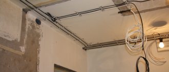
And it is also very important after completing the first stage
to photograph all the wires so that the gasket is visible in relation to the doorways, ceiling, and floor.
This may be very useful later, when you need to install a lamp, screw on a shelf, curtains, and so on. Fortunately, everyone has digital cameras and phones today. However, we are primarily interested in
What to check
It is known that the wiring in an apartment consists of wires carrying electricity and auxiliary elements, including couplings, fasteners, etc. The reliability and quality of electrical energy production will directly depend on the condition and serviceability of all these elements. In addition to these, sometimes the electrical equipment itself also needs to be checked. Experts recommend checking the wiring by testing the wires from one point in the circuit to another.
How does a multimeter work?
Even a beginner who has never dealt with electrical work can ring the wiring. The main thing is to be careful. To test the wiring, the multimeter must be switched to resistance testing mode. After this, the clamps are connected to the ends of the electrical wires. High-quality cables should have a resistance that will not exceed 1 ohm. If the wiring in the apartment is faulty, it will have resistance, which is sometimes even more than 10 ohms. If one of the wires in the wall is broken, the device will display a unit on the left side of the screen. This means that the measured resistance is greater than 200 ohms. In this case, it can be stated that the contour has a significant gap.
Using a multimeter, in addition to checking the wiring, you can also check the performance of batteries, determine the voltage in the apartment's sockets, as well as the current strength in high-voltage wiring.
Checking the circuit for open circuit
To check the circuit for an open circuit, in addition to a multimeter, you can also use a special tester. Such a device is a metal rod in an insulating material with a light bulb, a battery and a clip connected to the wire. The tester makes it very easy to determine whether there is voltage in the wiring in the apartment. To check for a break, fix one end of the wire with a clamp, and touch the other with a rod. If the light on the device lights up, this means that electric current is passing through the area.
It is important to note that before checking the circuit for an open circuit, you need to turn it off
Wood is an extremely grateful material. Strong enough to last, hard enough to hold even a very thin shape, enough.
Karambit is a very specific melee weapon that became suddenly popular thanks to the game Call of Duty: Black Ops, and also numerous.
Cable testing is an essential tool for an electrician.
The standard and most common case is when there is no voltage in any outlet or lighting fixture, and sometimes in all of them at once. In this option, there is no choice - it is necessary to test the cable that powers the entire system, and then individual wires.
As a rule, in the distribution boxes of apartment buildings there is a tangle of unmarked and somehow insulated ends. Switches and sockets, especially in old houses, have long outlived their useful life. It is not easy to understand this intricacy and determine the specific place where the circuit break occurred. We have to check all the elements and re-label the cable cores.
Often the work is complicated by the fact that it has to be carried out without turning off the electrical equipment, but for these situations there are various devices and instruments produced by industry that allow you to find breaks even inside the walls. But in the conditions of a separate apartment or house, wiring can be done in simpler ways:
- with a complete power outage using a multimeter;
- or without switching off - with an ordinary light bulb.
What you need to know about the device to connect wires
If you plan to test the wiring in your apartment, you need to know several fundamentally important facts about multimeters. First of all, it is worth noting that you can check the wire with the simplest device. An inexpensive Chinese model with minimal capabilities is quite suitable.
But at the same time, it is most convenient to use a device that has the dialing function itself. In order to set the device handle to the appropriate position, you need to turn it in the direction of the diode icon (as an option, an image of a sound wave can additionally be applied). This means that when checking the integrity of the wire, a sound signal will sound when the contacts are closed.
But the presence of sound is completely optional for testing wires with a multimeter. The fact that the circuit is broken will be indicated by a unit on the display, indicating that the resistance level between the probes is higher than the measurement limit. If there is no damage in the area under study, the resistance value will be displayed on the screen, which ideally should tend to zero (subject to operation in short-distance household networks).
Sequence of actions when calling
- Before you test the circuit with a multimeter, you need to turn the handle of the device to the desired position.
- Install the ends (measuring leads) into the appropriate sockets. The black wire goes into the socket marked COM (sometimes it can be marked with “*” or a ground sign), and the red wire goes into the socket where the Ω sign is indicated (sometimes it can be marked with an R sign). It is worth noting that the Ω sign can be applied either separately or in combination with the designations of other units of measurement (V, mA). This is the correct position of the test leads, which will allow you to maintain polarity when making further measurements. Although if only the integrity of the wires is checked, their relative position will not affect the result obtained.
- Turn on the device. A separate button may be provided for this, or activation may occur automatically when the knob is turned to the desired position when selecting measurement limits or operating modes.
- Connect the measuring ends to each other. If a signal sounds, it means that the device is operational and ready for use.
- Take the cable or wire being tested (its ends must first be stripped of insulation, stripped to a metallic shine, and dirt and oxides removed from the surface). Touch the test leads to the exposed areas of the conductor.
- In case of continuity, a signal will sound, and the device readings will either be 0 or indicate the resistance value. If the display shows 1 and there is no beep, the tested conductor is broken.
Old-fashioned methods of searching for hidden wiring
Our grandfathers and great-grandfathers did without any instruments to search for hidden wiring, and at the same time they accurately found the electrical wiring line under plaster and wallpaper without any problems.
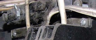
The easiest way is when a major renovation is done in a house or apartment. That is, the wallpaper is peeled off, and there are traces on the wall where the electrical wiring runs. This is roughly what it looks like.
The next method, which our grandfathers and great-grandfathers used, is to take a radio, tune it to a frequency of 100 kHz, and slowly move it along the wall. In the place where the electrical wiring will be laid, you will hear characteristic noises and cracklings in the receiver's speaker.
Why check the wiring when purchasing?
When buying real estate on the secondary market, a person always takes risks. The seller is interested in selling his property as profitably as possible, and he will strive to hide as much as possible all existing shortcomings and defects. (You should not blindly rely on human decency - there are very few truly honest people in any market.) If, when inspecting a house, you do not determine the phase and do not carry out the necessary technical examinations, then you can run into trouble some time after the purchase. For example, if the purchase takes place in the summer, then in the winter it may turn out that a lot of debris has accumulated inside the heating system (small pieces of rust that form there naturally), which is why the house does not warm up well or does not warm up at all.
What does an electrical wiring inspection include?
There are several possible scenarios when you need to check the electrical wiring yourself:
- Certain sockets in the apartment do not work or the light does not turn on in one of the rooms;
- Knocks out the circuit breaker. When you try to turn on the circuit breaker, the knockout is repeated;
- You are planning a renovation and need to find hidden electrical wiring routes for your apartment;
- You are planning a major renovation of your apartment and need to diagnose the old electrical wiring.
These are not all cases that give a “bell” that it’s time to think about the electrical wiring of the apartment and house. You can add to this list:
- Purchasing a new powerful household appliance;
- Buying an expensive electronic device;
- Desire to install a new chandelier;
- You felt that the washing machine was receiving an electric shock;
- You constantly smell a slight smell of heated plastic (it's hard not to recognize it).
Electricity in the kitchen
If your stove has various electrical equipment (electric spit, electric ignition), then the gas supply should be carried out using an insulating insert. If an electric current leak occurs, the supply line, which is not insulated from the stove, can quickly become hot, and then the gas will ignite.
All electrical appliances must be located at a sufficient distance from water sources so that drops do not fall on them . After all, electricity and water are bad neighbors.
- Author: Oksana
Rate this article:
- 5
- 4
- 3
- 2
- 1
(0 votes, average: 0 out of 5)
Share with your friends!
Testing home electrical wiring
We will talk about an apartment in which the wiring of power lines complies with modern standards and requirements: each room has a separate line, and its power is supplied through its own “automatic machine”.
If the light in a room suddenly goes out, but in all other rooms it lights up normally, then first of all you need to check whether the light device is working. Before starting work, the power supply to the room must be turned off. If the lamp lamp is transparent, the broken filament will be immediately visible; if not, you will have to test it with a multimeter.
First you need to see whether the circuit breakers in the electrical panel have worked or not. If they are on, the problem most likely lies in the socket, switch, or the light bulb itself, and the wiring is fine. When the machine is triggered, it is necessary to check all elements of the circuit, except the switch, including the switch itself.
The machine didn't work
If the light goes out and the switch remains in the on position, then you first need to ring the switch. If it is working properly, then when the element is in the on position, the multimeter should emit a sound signal, and when it is off, the number 1 should appear on the display if there is no sound.
Further checking occurs in the following order:
- Turn the multimeter into voltage measurement mode, and then check the input and output of the switch.
- If there is a potential difference on the machine, unscrew the light bulb from the socket and touch its central contact with one probe and the base with the other. If there is no signal and the display shows 1 or 0, the lamp is faulty.
If the check shows that the light bulb is working, you should proceed to testing the socket. Having disassembled the lighting device, you need to inspect the connected conductors and contacts. If a visual inspection does not reveal any problems, the problem is not in the cartridge.
Such a check usually reveals that one of the listed elements is faulty. After replacing or repairing it, the problem disappears.
The machine worked
If the light in the room turns off along with the operation of the machine, first of all you should check the cartridge and the integrity of the cables connected to the lamp. How this is done was described above.
Damage to it occurs infrequently, but sometimes occurs, for example, when installing decorative parts or installing suspended ceilings.
The procedure for dialing the electrical line is as follows:
- Disconnect the supplied cable and move it to the side using a screwdriver.
- Unscrew the incandescent light bulb from the socket.
- Put the multimeter in dialing mode. Use one of the probes to touch the neutral wire, and the other to the end of the disconnected wire. The tester's sound signal will notify you of a short circuit in the electrical wiring.
- After making sure that there is a short circuit, you need to find and then open the junction box and disconnect the conductors in it from each other.
- Check all cable groups for short circuits. To determine a closed section, you must first ring the circuits located on the apartment electrical panel with a tester. The signal that is heard will indicate a malfunction of the conductor leading from the panel to the junction box. If it is OK, then the diagnosis continues until a damaged cable is detected.
An example of searching for a broken wire in the video:
In this material, you learned how to test wiring to detect faults using a multimeter. This procedure is quite simple, but when carrying it out, as during any other electrical installation work, safety precautions must be strictly observed.
How to identify problems
You can check whether there is an open circuit with a tester or a multimeter in ringing mode. To speed up the search, you need to clearly understand that current flows from the input device through the distribution boxes to the sockets and lighting fixtures.
For example, if there is no voltage in the outlet, but there is voltage in the other outlets connected to the same box, the problem is in the area between the box and the faulty outlet.
If there is no voltage in all sockets connected to the box, the break should be looked for in the area from this box to the previous distribution box.
If there is no voltage on the lamp, it is necessary to check the wiring section up to the switch, for which the presence of voltage between phase and zero is checked.
To connect to zero, you can use an auxiliary piece of wire, since there is most likely no zero in the switch. If voltage is present at the switch, the presence of voltage is checked at the contacts of the lamp when the switch is on.
The search area for a short circuit is significantly reduced, and the search is faster if the circuits in the distribution board are divided into rooms and each protected by its own protective device. In this case, to check, it is necessary to turn on the machines one by one, and, based on the one that worked, determine the area for troubleshooting.
You can check whether there is a short circuit with a tester or multimeter by measuring the resistance between the phase wire and the neutral wire or between the phase and ground wires, separately in sections of the circuit.
To do this, you need to physically turn off all devices, that is, remove the power cords from the sockets, unscrew the lamps from the lighting fixtures. And, of course, be sure to de-energize the entire network. This is the simplest verification method. You can use a hidden wiring detector to find faults, but the accuracy of determining the location of the fault in this case is low.
Malfunctions such as failure of electrical installation products - sockets, switches - are possible. These products are usually in plain sight and finding problem areas is not very difficult. Checking such products consists of inspecting contacts and housings. The malfunction is detected by the presence of burnt contacts and melted housings.
How to ring a wiring
Testing the socket with a multimeter
The easiest way is to contact specialists. If you master the rules and techniques, you can cope on your own.
Rules for safe wiring
Operations with electricity require compliance with technical safety standards. In addition to maintaining health, the rules allow you to complete the job quickly and accurately. The main points include:
de-energizing the circuit; the ends of the wires must be secured with lugs - “crocodiles”; When checking long wires, it is important not to touch them with your fingers; Multi-core cables are separated and stripped.
The last rule is important when working with circuits that are designed for high voltage networks. If the load is small, you can simplify the process
How to check wiring during installation
Cable laying in the groove
The wires are laid in special grooves (recesses) or along the walls. This is followed by the stage of plastering and finishing. Checking the wiring in an apartment or other premises is carried out up to this point.
Builders and electricians make mistakes. In the first case, it is necessary to carefully monitor and check the work. In the second, use the prepared diagram and promptly check the wiring in the apartment (before plastering and finishing). Checking the electrical wiring begins with the following activities:
- visual inspection;
- short circuit test;
- checking with a megohmmeter;
- ringing
How to test wiring with a multimeter
To test the wires in an apartment, the easiest way to understand the operating diagram is to use a multimeter. If we assume that the electrical system was initially installed according to all the rules, the check will not take much time.
When a light bulb goes out in a room, the first thing you need to do is check if it is working properly. De-energizing the room is the initial stage. Testing the wiring with a multimeter is a quick and safe way to check the electrical system in an apartment. If you follow the rules and safety requirements, you can do this yourself.
Safe and correct operation of the multimeter
Working with electrical devices and networks must be safe. This rule also applies to the procedure for ringing conductors with a multimeter. Let us highlight the main recommendations that must be followed before and during work:
- First of all, the circuit must be completely de-energized by turning off the machine in the switchboard and removing the batteries (if the object in question is an electronic device).
- The capacitors in the circuit must be discharged by short-circuiting. Otherwise, during measuring work, the multimeter may fail.
- For convenience when making measurements, it is recommended to use special tips (“crocodiles”) at the ends of the measuring wires. These devices create reliable contact with the conductor being tested and, at the same time, free your hands.
- When trying to fix the probe, it is not recommended to touch the bare wires and the tip of the probe with your fingers. Otherwise, the results obtained may be incorrect.
Checking the wiring with a multimeter
To avoid mistakes, the electrician’s work must be checked in a timely manner using the dialing method. This is done using a multimeter set to AC voltage.
You should start with the junction box. It contains a bunch of unmarked wires. First you need to find the phase wire at the output and mark it with electrical tape. Then they find zero: touch the phase with the probe of the device, and alternately touch the remaining ends of the beam with another probe. A value of about 220 V appears on the indicator - the neutral conductor has been found.
Conductor integrity check
To check the integrity, you need to disconnect the conductor from the power source. The multimeter is set to Ω. Its probes are connected to the ends of the conductor. An entire conductor will show zero resistance. You can call your home electrical network without involving specialists. To do this, you need to look at the position of the machines.
If the machines don't work
If the circuit breakers do not work, you need to ring the circuit breaker. When turned on, the multimeter will produce a beep. After this, the voltage at the input and output terminals of the machine in the house is checked. If there is voltage, the light bulb is unscrewed from the lamp socket. One measuring probe touches its central contact, the other touches the base. If the lamp is working properly, a signal will sound from the device. A burnt-out lamp should be replaced. If the lamp is working, check the socket, then the switch in the room.
If the machine worked
When the circuit breaker is turned off, they look for the cause of the short circuit between the phase wire and the neutral or protective wire. Use a screwdriver to disconnect it and move it to the side. The lamp is unscrewed from the socket. The probe of the device is connected to the neutral conductor and to the phase. An audible signal will indicate a fault in the circuit. In this situation, you need to open the box near the ceiling and disconnect all the wires in it. Each is checked for short circuits.
Checking the outlet
You need to unplug the outlet, and only then can you remove the cover from it and inspect all the parts. If there is no carbon deposits or visible damage, you need to connect the device probes to the terminals. The tester shows infinity - the socket is intact, there is a fault in the wiring. Then check each conductor separately using the methods described above.
Check at the installation stage
At this stage, you need to pay attention to possible problems with laying the electrical network. It is mounted on bare walls and covered with finishing materials
The check is carried out before the start of plastering work. During this period, electrician errors are easily detected when carrying out electrical installation work on the walls of the house. To perform the operation, take a wiring diagram that will help you understand the tangle of wires.
Types of faults
Faulty electrical wiring can cause fires and electric shock. Basic electrical wiring faults can be of two types:
- wire breakage, and, as a result, lack of electric current in any part of the circuit;
- short circuit of a phase wire with a neutral or ground wire, which leads to the circuit being disconnected by protective devices.
Checking and troubleshooting hidden wiring is greatly facilitated if there is a detailed diagram of the wiring in the room. This diagram is mandatory when drawing up a technical passport of the premises.
If there is no diagram, you need to determine the location of the wiring routes in the walls. Subject to compliance with the requirements of the PUE, wires and cables must run in a straight line connecting distribution boxes with sockets and switches. In this case, the routes must be strictly vertical or horizontal.
Wiring and requirements for it
The first and very important point that you should know about before starting electrical installation work is that in panel houses (Khrushchev-era buildings) you most often cannot trench walls in accordance with Moscow Government Decree No. 73-PP dated February 8, 2005 “On the procedure for renovating premises in residential buildings on territory of the city of Moscow." Also, according to Government Decree No. 508 (Clause 11.3 and 11.11 of Appendix No. 1), it is prohibited to tap load-bearing walls.
In this case, it would be rational to conduct wiring through existing channels, the floor or under the ceiling (if a suspended or suspended ceiling is planned). The first and last options are more preferable. If the electrical wiring in the apartment is changing and you plan to cover the walls with plasterboard, an excellent solution would be to lay the wiring behind the plasterboard.
Important! It is strictly prohibited to scratch the ceiling in the apartment! The only option in which you can make grooves on the ceiling is to first apply an additional layer of plaster to the ceiling, in which the cable will be hidden. This layer can already be carefully grooved without touching the monolith
Those. The simplest option is to draw lines from the panel to the sockets and switches along the ceiling, ducts or floor, and then make vertical grooves and so-called wells for installing socket boxes.
Another important point that you should pay attention to if you decide to do the wiring in the apartment yourself is that noisy work is allowed from 9 am to 7 pm (except Sundays), while an hour of silence must be provided from 1 pm to 3 pm! Shredding is a noisy job and can not only cause the anger of neighbors, but also cause a fine (from 1 to 5 thousand rubles for individuals)
Let's return directly to the installation of apartment electrical wiring. As we said earlier, the length of the conductors must be purchased with a reserve. This reserve will be used to connect them to each other (on each side the outer sheath of the cable is removed by 5-10 cm) and to connect sockets, switches, lamps (the length reserve is from 10 to 15 cm).
The video shows how to correctly install electrical wiring in an apartment without breaking the rules:
Why is planning for outlets and switches important?
Errors in planning the number and layout of the main electrical points lead to the fact that there are not enough sockets, and tees and extension cords have to be used. And these devices create physical discomfort, spoil the interior design, and create additional danger. Therefore, there must be enough sockets for all consumers. But their number must meet all fire safety requirements so that there is no excessive load on the wires and the residual current devices do not trip.
The location of the switches should be convenient so that, for example, you can turn the light on and off without getting up from your chair (chair, bed).
Source: nadzora.ru
Calculation of the need for materials and accessories
The required amount of material is determined in two ways:
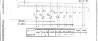
- according to the wiring diagram - the most accurate;
- for the total area of the apartment - approximate.
When calculating the cable according to the diagram, the total length of the electrical wiring marking is measured, to which 10% is added, plus 20 cm for each socket or switch, plus 50 cm for each lamp and 50 cm for the distribution panel.
To calculate the need for cable based on the area of the apartment, the numerical value of the housing area is multiplied by 4, and the total footage of the wire of all sections is obtained. 40% of the obtained value is the length of the cable for lighting, the remaining 60% is the footage of the power cable.
Cable sections of wiring sections are calculated in relation to the wire material, laying method and maximum load on the line. For the convenience of selecting the required wire, the cross-sectional values are tabulated depending on the specified factors:
| Cable cross-section (mm2) | Open installation | Pipe installation | ||||||||||
| Copper | Aluminum | Copper | Aluminum | |||||||||
| Current (A) | Power, kWt) | Current (A) | Power, kWt) | Current (A) | Power, kWt) | Current (A) | Power | |||||
| 220 V | 380 V | 220 V | 380 V | 220 V | 380 V | 220 V | 380 V | |||||
| 0,5 | 11 | 2,4 | — | — | — | — | — | — | — | — | — | — |
| 0,75 | 15 | 3,3 | — | — | — | — | — | — | — | — | — | — |
| 1,0 | 17 | 3,7 | 6,4 | — | — | — | 14 | 3 | 5,3 | — | — | — |
| 1,5 | 23 | 5 | 8,7 | — | — | — | 15 | 3,3 | 5,7 | — | — | — |
| 2,0 | 26 | 5,7 | 9,8 | 21 | 4,6 | 7,9 | 19 | 4,1 | 7,2 | 14 | 3 | 5,3 |
| 2,5 | 30 | 6,6 | 11 | 24 | 5,2 | 9,1 | 21 | 4,6 | 7,9 | 16 | 3,5 | 6 |
| 4,0 | 41 | 9 | 15 | 32 | 7 | 12 | 27 | 5,9 | 10 | 21 | 4,6 | 7,9 |
| 6,0 | 50 | 11 | 19 | 39 | 8,5 | 14 | 34 | 7,4 | 12 | 26 | 5,7 | 9,8 |
| 10,0 | 80 | 17 | 30 | 60 | 13 | 22 | 50 | 11 | 19 | 38 | 8,3 | 14 |
| 16,0 | 100 | 22 | 38 | 75 | 16 | 28 | 80 | 17 | 30 | 55 | 12 | 20 |
| 25,0 | 140 | 30 | 53 | 105 | 23 | 39 | 100 | 22 | 38 | 65 | 14 | 24 |
| 35,0 | 170 | 37 | 64 | 130 | 28 | 49 | 135 | 29 | 51 | 75 | 16 | 28 |
When calling a conductor a cable or a wire in everyday life, you should know that these are not synonyms:
- wire is a stranded or single- or stranded conductor with or without light tubular insulation;
- a cable is a system of insulated conductors combined into a single structure, which is additionally insulated and, depending on the model, protected by an armored casing.
As for the material used to make the cores, the regulatory documents clearly define the following:
PEU 1.7.34 “... Cables and wires with copper conductors should be used in buildings...”
SP 31-110-2003, clause 14.3 “Internal electrical networks must be flame retardant and made with cables and wires with copper conductors in accordance with the requirements of 2.1 and 7.1 PUE.”
For equipment with a power of more than 2.0 kW, it is recommended to connect a separate power line with a circuit breaker, the rating of which can be determined from the following table:
| Cable cross-section (sq. mm) | Current (A) | Power, W) | Machine rating (A) |
| 1,5 | 15 | 3300 | 16 |
| 2,5 | 21 | 4600 | 20 |
| 4 | 27 | 5900 | 25 |
| 6 | 34 | 7400 | 32 |
What to look for?
In new buildings, it is recommended from the very beginning to calculate the total power of electrical appliances that are planned to be used. Based on this, calculate the total load and the required cable cross-section, compare the data obtained with the characteristics of the wire that has already been laid. After this, check the condition of the hidden wiring. The insulation must be intact, all connections must be reliable and safe. Be sure to check the grounding and the correct assembly of the distribution board.
In old housing, it is important to pay attention to how worn out the wiring is. Most often this is visible with the naked eye, and even a non-specialist can determine it.
You can quickly check the condition of the electrical wiring using a multimeter.
Testing wires with a multimeter
Manufacturers make different types of multimeters, but the measurement principle remains the same, only the location of the controls and measurement limits differ. To check the integrity of the wires, the measurement mode switch is placed in the continuity position; this is marked with a diode or buzzer sign. After which the dialing process is carried out using the methods described above. The integrity of the conductor, in addition to the display of zeros (no resistance), is accompanied by an audible signal or an LED indicator, this depends on the brand of the multimeter. article: → “How to use a multimeter for dummies?”
Multimeter GE 2524 in dial position
The probe with the black wire is inserted into the connector with the ground symbol (case), the red one above, into the connector for measuring resistance with the Ohm symbol “Ω”. The disadvantage of many digital multimeters in dial mode is the delay in the sound indicator signal when touching the contacts. It is necessary to fix the probes on the wire for 2-3 seconds to make sure there is contact. This inertia in operation creates some difficulties in checking the integrity of the wire.
Multimeters of the UNI-T type have good performance in dialing mode; the sound indicator operates almost instantly when the contacts are closed.
In other parameters, UNI-T is not inferior to other models in measurement accuracy and number of options. article: → “Checking circuits with a multimeter or tester.”
Comparison table of characteristics of Fluke-179 and UNI-T UN61 multimeters
Please note that for all instruments it is advisable to use probes with gold-plated rods. Unlike steel ones, they are not subject to oxidation and provide reliable electrical contact.
Features of using a multimeter
If you want to determine the integrity of electrical wiring in an apartment, then you need to know the features of using a multimeter. First, you need to know that for such purposes you don’t need an expensive device; you can get by with a simple Chinese tester that does not have special capabilities.
However, the most practical option is to use a device with dialing capabilities. To turn on the mode we need, turn the tester knob to the icon that shows a diode or a picture of a wave. In this mode, if the conductor is working properly, a squeak will be heard.
The sound signal will not always appear. If the wire is faulty, the number one will appear on the screen, which indicates that the resistance is higher than the limit in the measurement. If the circuit is working properly, the conductor resistance will appear on the display. In the best case, this indicator should be around zero if the conductor is short.
The continuity of wires and cables is as follows:
You need to turn on the multimeter. We connect the wires for measurement to the multimeter. The black wire must be connected to the black socket, and the red wire to the red socket
It is important to connect the wires exactly so that you do not get confused with polarity when measuring. In the event that you simply need to find out whether the wire is intact, then the position of the conductors can be neglected. Next you need to turn on the tester
It can turn on immediately when you select a mode, or you need to do it manually by pressing the desired button.
- The next step is to check the serviceability of the device. To do this, you need to connect the multimeter probes to each other. If you hear a squeak, then everything is in order and you can start testing the cables.
- After this, you should take a conductor with well-exposed wires, without dirt and oxidized metal, and touch the ends of the cable with the probes.
- If the circuit is working properly, you will hear a characteristic sound, and the display will show the resistance value or just zero. If the number one appears on the screen, but there is no squeak, this means that the circuit is faulty.
Search methods
To search for wiring, you can hire a specialist, or you can conduct an independent search using specially designed devices and tools. Which of these options to choose is up to everyone to decide for themselves.
Devices
- Probe MS-158M, MS-48, MS-18 - in addition to wiring, they find metal inclusions in the wall (nails, screws, etc.), react to slab reinforcement at a depth of up to 5 cm.
- Alarm E121 “Woodpecker” - responds to an electromagnetic field and detects breaks in live wires at a depth of up to 7 cm.
- POSP-1 – detects the presence of alternating electricity and wire breaks.
- CEM LA – 101 – reacts to the electromagnetic field, detects wire breaks.
- Non-contact sensor ExtechDA30 – detects the electromagnetic field of alternating voltage. Works with cable ducts, shielded wires, distribution boxes.
- MS58M - reacts to metals, no voltage required in the wires.
- Hidden wiring detection device "OSP" - for accurate and quick search of electrical wiring breaks. When using a generator (supplied) it finds wires disconnected from electricity. Finds copper at a depth of up to 30 cm.
Various types of thermal imagers are prohibitively expensive, but clearly detect live wiring and its breaks.
Scanner
The main difference between scanners and other devices that are used to detect electrical wiring is that they can “see” not only wires.
- Black&Decker BDS300 detector – finds electrical wiring, non-ferrous and ferrous metals, wood.
- Metal detector ZirconTriScannerPROSL - in addition to detecting metals, scans live electrical wiring in all operating modes.
- The Skil 0550 AA detector is a liquid crystal indicator that, in addition to detecting metals, scans live electrical wiring in all operating modes.
- The Bosch PDO Multi digital detector is the most budget-friendly of the Bosch family; it detects potential wiring (phase), materials inside walls and their depth.
Multimeter
A multimeter is usually called a device that can replace several other devices. In our case, the multimeter combines an ammeter, an ohmmeter, and a voltmeter.
The most common ones to look for electrical wiring are:
- The tester - multimeter LA-1014 - accurately determines the location of de-energized and live wires, the state of computer and telephone lines, places of breaks, overlaps, and short circuits.
- Testers GVD-504A, GVD-503, GVT-92, VP-440 - analyze the condition of the hidden cable, determine the location of breaks.
There are a huge number of different devices that are designed to search for wiring. The use of most devices requires experience in operation to correctly distinguish the signals that come from them.
Using a smartphone, telephone
You need a smartphone or phone equipped with a magnetic sensor and a special Metal Detector program designed to search for metals.
Determines the location of the wire by the electromagnetic field that occurs in live wires.
Also, such a finder is capable of finding the location of a wire break and fittings in panel houses. The work of such an indicator is not of high quality and requires preliminary training.
The search accuracy depends on the position of the device relative to the surface being scanned.
Indicator screwdriver
Searching with an indicator screwdriver is the easiest and cheapest option. Determines the electromagnetic field with an accuracy of search width from 10 to 20 cm.
This screwdriver can be used to check the continuity of the circuit. It does not “see” de-energized and shielded wires. Detects electrical wiring at shallow depths.
Without devices
Remove wallpaper from the walls and determine the presence of wiring by looking at the unevenness of the plaster.
This method is applicable only if the surface of the panel is not completely plastered, but rather the method of laying wires in grooves.
Use a wiring designation map (a very unreliable method even in new apartments, since the map does not always correspond to the work done by the electricians).
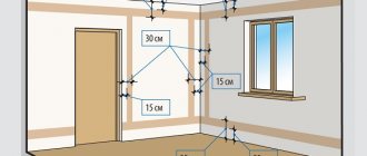
Professionally installed electrical wiring should be 15 cm parallel to the ceiling, and vertically upward, from sockets and switches.
In panel houses, the wiring can be laid along the shortest path (diagonally) from the distribution boxes, and in houses with multiple renovations, it is generally messy.
Causes of malfunctions in car wiring
A vehicle's electrical system has primary charging circuits for starting and charging the battery, as well as additional circuits such as electric lights, electric motors, sensors, magnetic locks, a stereo system, and a computer. All circuits are opened and closed by switches or relays (remote switches controlled by electromagnets).
Current in the circuit flows through one battery cable, through a live component, and into the battery through the metal body of the vehicle. The housing is connected to the battery ground terminal with a thick cable.
In a negative (-) grounding system, current flows from the positive (+) terminal to the operating component. A vehicle body ground component that connects to the negative (-) terminal of the battery.
In practice, there are quite a few probable causes of failure of automotive wiring. Here are the most common reasons for leaving them:
- The aging process that results in brittleness, cracking, and eventual failure of insulating materials. This exposes the wires in the car and creates the risk of a short circuit, which can lead to a fire in the car.
- A wire has been installed that is not suitable for the power and operating conditions in the vehicle, is not mechanically resistant enough to wear or abrasion, or is chemically unstable to environmental conditions.
- Mechanical failure due to shock or vibration.
- Moisture penetration into insulation causes serious problems, including short circuits and corrosion of copper wires.
- Overheating of electrical cables leads to deterioration in the quality of the insulating material of the outer sheath, as well as to premature failure of the cables.
- Electrical overload.
- Rodent damage.
How to check electrical wiring at the installation stage
Let's figure out what potential problems an electrician can expect when laying new electrical wiring.
Typically, new wiring is laid either in special grooves or along bare walls. Then the walls are plastered and further finishing is carried out. Therefore, the first check is carried out before starting plastering work. Otherwise, it may be that in order to fix the problem, you will have to re-drill the walls and open the plaster.
At this stage, problems can occur for two reasons: due to errors by builders (concrete workers or finishers) or due to errors by electricians.
To avoid wiring problems that can result from builder errors, you need to be very careful and vigilant. And in order to avoid electrician mistakes, you need to lay the wiring according to a pre-drawn diagram, and also carefully check and call the electrical wiring before starting finishing work.
What needs to be done in order to know for sure that the wiring is working properly?
- It is necessary to check the electrical wiring for a short circuit, that is, make sure that there is no contact between phase, neutral and ground.
At high voltages, the quality of the wire insulation depends on the quality of the cable, so you should not save when buying a cable and purchase the cheapest option.
If you have any doubts about the insulation of the wires, you can check them using a megohmmeter.
Visually inspect the wiring for mechanical damage. Any damage must be repaired before plastering or other finishing work begins.
If you are convinced during the check that everything is in order, then you can proceed to checking the electrical wiring. Below is an algorithm on how to ring wiring, which can be used for both new wiring and the one that already exists in your apartment.
Homemade contactless dialing
Below is a diagram of a simple non-contact break detector; it can be assembled within one evening. Considering the small number of parts, you don’t have to bother making a printed circuit board, but use wall mounting.
Detector circuit
List of required radio components:
- variable resistance R1 – 100 kOhm;
- resistor R2 – from 4 to 8 MOhm;
- electrolytic type capacitors: C1 and C3 – 220 µF, C2 – 33 µF;
- ceramic capacitor with a capacity of 0.1 μF;
- D1 – LAG 665 chip (preferably in a DIP package);
- SP is a regular earphone from a telephone headset.
The circuit can be powered from a source with a voltage of 2 to 5 volts.
The dipstick (P) is made on the basis of a regular spoke from a bicycle wheel.
Probe for a homemade break detector
Properly assembled contactless cable testing does not require adjustment.
Video: Do-it-yourself cable testing. How to test wires using a light bulb and battery
If you calculate the cost of all the necessary parts, it is easy to see that the result obtained will be an order of magnitude less than the cost of services for detecting a broken wire, indicated in construction estimates.
{SOURCE}
How to check the integrity of a conductor
- First you need to completely disconnect the conductor from the power source. If the conductor is a multi-core cable, then you need to disconnect all the wires that enter it.
- The multimeter must be turned on either in the dialing mode or in the resistance measurement mode. If the resistance measurement mode is selected, then you need to set the maximum limit.
- You need to connect the multimeter probes. If the device is in ringing mode, it will emit a sound signal, and if in resistance measurement mode, zeros will appear on the display.
- Then you need to open the multimeter probes and attach them to the conductor. If the conductor is intact, it will show zero resistance.
- If the conductor is multi-core, then the actions are the same. The only difference is that if the conductor cores do not differ in the color of the insulation, then they must first be marked.
If checking the cable shows that the conductor is intact, then the cause of the problem must be looked for in some other place.
You can find a cable break or find the location of a short circuit, as well as ring the wiring in the apartment yourself. Actually, it's not that difficult. The most important thing is not to neglect safety rules, even if you are an experienced electrician.
The principle of testing and determining resistance
If you carefully examine the multimeter, you will notice that the continuity mode (diode testing) is in the resistance measurement zone. In simple words, continuity testing combines the determination of conductor resistance, analysis of the data obtained and output of the result with an additional sound signal.
To understand the principle of dialing, it is enough to first know Ohm's law. It states: “the strength of the current in a conductor is directly proportional to the voltage at its ends (potential difference) and inversely proportional to the resistance of this conductor.” Based on this rule, resistance R = U ⁄ I, where I is the current strength, U is the network voltage.
Knowing how resistance is determined, it remains to understand where the current and voltage come from during measurements (for safety reasons, the circuit being tested must first be de-energized). It's simple. The multimeter has a power source that creates voltage and supplies current. By comparing the initial data with the amount of loss caused by connecting to the measured resistor, wire or light bulb, the final result is calculated (unit of measurement - Ohm).
Calling the wiring
Dialing tools
Multimeter for dialing
Most often, testing is done with a multimeter - a special device designed to record various parameters of an electrical connection (current, voltage, resistance, etc.).
A simple multimeter is inexpensive and therefore deserves a permanent place in your toolbox.
A multimeter set to dial mode (most often indicated by the corresponding icon) will help you if necessary:
- Check contact availability
- Check the integrity of the electrical circuit
- Check the operation of the switch or socket
- Figure out which of the cable bundles (a very common situation in our apartments) is connected where.
Multimeters can be digital or analog, but the principle of their operation remains the same.
We will tell you how to use a multimeter to test wiring in the next section.
Testing with a multimeter
When testing the wiring using a multimeter, we perform the following operations:
We set the dialing mode on the multimeter - most often it is marked with an LED.
Then we move on to the place where the wiring rings - the junction box. There, as a rule, we are presented with a bundle of unmarked wires. We find the phase - after turning on the machine, we check all the wires using an indicator screwdriver. We mark the found wire using insulating tape or window tape.
- Next we look for zero. We turn on the multimeter to measure voltage (if we need to find 220V, we set it higher - for some models it is 600 V). Then we touch the phase with one multimeter probe, and with the other we test the wires one by one. As soon as the required 220V appears on the multimeter, the wire we need has been found. We mark it too.
- We check other pairs of wires using the same principle, and mark them in the same way.
Using a multimeter, you can not only test the wiring in the junction box, but also check whether there is a break in the wire (for example, in the power cable).
Conductor integrity check
We check the integrity of the conductor as follows:
- Disconnect the conductor from the current sources. If the conductor is a multi-core cable, then we do this for all the wires included in it.
- We turn on the multimeter either in the continuity mode, or in the resistance measurement mode at the roughest limit.
- We connect the probes of the multimeter: zeros should appear on the display, and in the ringing mode with sound accompaniment, the device will make a squeak.
- We connect the open probes of the multimeter to the conductor. An entire conductor shows zero resistance.
- For a multi-core cable, the verification procedure is the same, but you must first mark the corresponding cores (if they do not differ in the color of the insulation).
If, after checking, no violations of the cable integrity are detected, then the fault should be looked for elsewhere.
Testing the wires in the apartment, searching for a cable break or a short circuit can easily be done independently. And yet, we remind you once again - even if you are an experienced electrician, do not forget about the safety rules!
How to find a broken wire in the wall
First steps and checking the switchboard
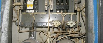
So, while for unknown reasons the lights went out in the room (one, several or all at once), electrical appliances stopped working. The first natural action of the owners is to check whether this is a general shutdown along the street (entrance of a city house). If not, pay attention to the switchboard - whether the circuit breakers have been knocked out or the fuses have blown - plugs (in some places such an anachronism is also found).
If everything is normal here, you will have to look for faults in your own domain.
Where do they start? First of all, by “turning on the logic.” It is worth immediately analyzing whether work related to drilling walls has recently been carried out in the apartment. Have there been any other emergencies recently, for example, a flood from the neighbors above.
We must try to remember whether there were any “symptoms of disease” in the wiring - blinking lights, the characteristic crackling sound of sparking contacts, the smell of burnt insulation. Sometimes even such information is enough to quickly locate the accident site with a high degree of accuracy.
Troubleshooting always starts from the switchboard. The first is visual control. If an accident occurred right here, it can give itself away as a jumping out of the terminal or a blackened contact on the circuit breaker (RCD). It is recommended that you immediately, armed with a multimeter set to measure alternating voltage of more than 250 volts, check whether there is voltage at the input circuit breaker. If the measurement readings are normal, there is definitely no need to sin on the supply, and the reason is definitely located inside the apartment.
Before making control measurements, it would be useful to once again make sure that the multimeter switch is set to an alternating voltage with a nominal value of at least 250 volts. Typically this is a limit of 500, 600 or even 750 volts (depending on the model of the device).
Of course, you can check with an indicator screwdriver, but it can only show the presence of a phase. And this is an ambiguous picture, since the break can also occur along the neutral wire.
Some advise using a simple device for such diagnostics, consisting of a socket with a lamp and two wires. Indeed, in this way, perhaps, it is easiest to determine whether the required voltage of 220 volts is available in a given place (at the terminal of the machine, in the distribution box, in the socket, etc.). However, working with such a homemade “tester” is very unsafe, and is strictly prohibited by labor safety rules. And the author, as a “law-abiding citizen,” also does not recommend such verification methods.
Not having a multitester should not be an excuse. Nowadays, anyone can purchase a very inexpensive, but at the same time quite “capable” tester. And any good owner should have such a device, along with an indicator screwdriver. So we will proceed from the premise that there is a multimeter available.
After checking, the introductory machine turns off, as well as all other machines. And the next step is to check the reliability of clamping of conductors in the terminals on all circuit breakers and RCDs, as well as in the zero and ground buses. If necessary, a tightening is performed. It also happens that this is where the elimination of the accident ends - everything, it turns out, lay in poor contact on one of the terminals.
The check usually starts from the switchboard - is there input voltage, what condition are the terminals in, are the circuit breakers and differential protection devices operational?
By the way, it would probably be appropriate to immediately focus on some common mistakes that are often made by inexperienced craftsmen when connecting wires to the terminals of an RCD.
- A copper stranded flexible conductor without termination is clamped into the terminal. Even with a seemingly high-quality cover, contact can weaken greatly over time. Or even disappear completely - pinched thin wires can break off. It is generally better not to use such wires in a switchboard - a single-core wire of the required cross-section will be more reliable. But if there is nowhere to go, then the wire must end with a terminal lug. Such parts are inexpensive, their installation is not difficult, but the contact will be reliable.
If stranded copper wires are used for switching, then terminal lugs must be pressed onto their stripped ends
- When connecting a wire, its stripped end is inserted too deeply into the terminal. And when tightened, the contact pad begins to rest against the insulation layer. It is clear that the crimping of the conductor itself turns out to be unreliable, which becomes a prerequisite for sparking, heating, and loss of contact.
- Two wires of different sections are connected to one terminal. When the terminal is tightened, the contact pad rests against the larger conductor, and the contact on the smaller one very often becomes extremely unreliable
In order to completely finish with the shield, you can, by turning on the machine at the input, sequentially check the functionality of all other circuit breakers, automatic circuit breakers and RCDs. It is clear that from each of them, if it is in the on position, a phase must come out. Here, an indicator screwdriver will be enough to check. Or, again, a multitester is used - the voltage is measured between the output of the machine (RCD, RCBO) and the common zero bus.
Having made sure that everything is normal with the switchboard, you can move on to searching for an emergency area in the apartment wiring itself.
Localization of the accident site
All of the above actions will be appropriate if the voltage disappears simultaneously in the entire room. But when a wire breaks in a specific area, most often the loss of power is also limited to a certain area of the apartment or house. Of course, if the distribution board was installed correctly, with the general supply branching out after the meter into separate lines.
For a good owner, this usually happens - there are several outlet groups, including separate outlets for powerful household appliances (washing machines, electric stoves, ovens, pumping equipment, etc.). Lighting can also be divided into groups, for example, by room. If everything is organized exactly like this, and there are signatures on the machines (or numbering with a “legend”), then the task is greatly simplified.
If the home electrical wiring is organized correctly, then the initial localization of the accident site will take a matter of minutes
That is, if the voltage is lost on a certain socket group, but checking the others shows that everything is normal, then it is immediately clear that there is a break on a specific line. It’s the same with the lighting, if it goes out only in a separate room (group of rooms), but in others the lights are on and the sockets are working.
Find out how to calculate lighting by room area by studying the algorithm and convenient online calculators in a special article on our portal.
But it often happens that the entire distribution is reduced to one or two machines, and the picture becomes unclear. In addition, some owners may simply not know the “legend” of their shield if they purchased an apartment or house with an already installed electrical network, and until now this issue has not yet bothered them. And it is strongly recommended to devote time to this in order to experimentally achieve clarity about which device in the dashboard is responsible for what.
The search for the break area is carried out from the switchboard to the point where the voltage loss is detected (socket, lighting fixture). The areas may be as follows:
- The route from the switchboard to the distribution box.
- The area from the junction box to the outlet (switch).
- The area between the switch or box and the lighting fixture.
There are often distributions in which the wiring to the socket groups does not include distribution boxes, that is, the wire goes directly from the switchboard to the end point. Moreover, a cable can also be stretched from one socket group to the next. This is immediately noticeable when two cables come to the socket: one of them goes from the switchboard, the other goes further to the next group.
So, the next task is to accurately determine the area where the break occurred.
Finding a section of wiring with a break
This task is not easy and quite tedious, especially if there is no wiring diagram. But still, after the initial localization of the accident, at least in a room or line, it will be easier to complete it.
At first it’s scary to take it on. But if a limited area has already been identified, in which a break most likely occurred, then it becomes easier.
The search begins from the switchboard. How can this be done?
An indicator screwdriver helps determine whether the phase is where it should be. For example, a phase is present at the output of the corresponding machine, then in the distribution box, but is no longer present at the socket located below. The conclusion suggests itself - the location of the accident is between the junction box and the outlet.
An indicator screwdriver is not always able to show the real picture
It would seem that everything is simple, if not for a few “buts” :
— Firstly, this method helps to determine exclusively phase wire breaks. But if the zero one is torn off, no result will be obtained. There may be a phase on a socket or lighting fixture, but the devices themselves remain inoperative.
— Secondly, such a test involves working with spiked voltage in the network. Let's be honest - it's not the best option for wiring that clearly has an accident, and even more so if the technician does not have sufficient experience in electrical work. To check, you will have to open the distribution boxes, deal with the twists or terminal connections in them, and due to inexperience you can get into trouble.
By the way, an indicator screwdriver, among other things, can also distort the real picture. It happens that the glow of the indicator does not indicate the presence of a full phase at all, but only about some kind of potential, which may well be due to leakage current from another “source”.
The same applies to measuring voltage with a multimeter. And working under voltage is dangerous, and voltage readings can be very contradictory.
What should I do?
The most reliable way is to call the sites. It will immediately show the integrity of the wire or the presence of a break in it. For this, the same multimeter is used, but only switched to resistance measurement mode, in the Ω position. Many testers generally provide a special mode for this purpose: if a section of the circuit has normal conductivity, the device emits a sound signal. The resistance of a copper wire is small (with a cross-section of 2.5 mm² - only 0.7 Ohm per 100 meters of length), that is, on the scale of a house or apartment it will be extremely insignificant - the indicator will display the value “0” or close to it.
Perhaps the most reliable way to find an area with an open circuit is to test the wires with a multitester
To carry out such an audit, of course, the line should be de-energized. After this, all wires of the line being tested are disconnected at the switchboard - phase from the machine, neutral and ground - from the corresponding buses.
Of course, it will not be possible to simply carry out a continuity test using the standard wires of a multimeter - the tested sections can be very long. For example, the switchboard is located in the hallway near the front door, and the distribution box is located in the room. This means that it is necessary to prepare in advance an “extension cord” - a piece of flexible copper wire of the required length so that it is enough to reach the most remote point to be checked. A large cross-section is not required - 1.0÷1.5 mm² is enough. This extension cord, of course, should also be checked for integrity in advance, that is, ringed.
And so that connections to the ends of the tested sections of wires do not cause difficulties, the extension cord can be equipped with an alligator clip or, which is even simpler and more convenient, a WAGO terminal with a lever lock. There will be no problems connecting the extension cord to the wire being tested. The same terminal can be placed at the second end of the extension cord - the free socket is perfect for inserting a tester probe.
WAGO's double lever-lock terminals, stopped at the ends of the extension cord, will eliminate all the hassles of quickly connecting to the wire under test. When connecting to twists, it will be more convenient to have an alligator clip at the end.
The section from the switchboard to the distribution box begins to ring first. To do this, sometimes you have to disassemble the contact connections made there in the box. Important - before disassembling, you need to remember (draw, film with a mobile phone camera) how the wires were connected. All this will not be so difficult if the wire insulation is color-coded (blue is always zero, green-yellow is grounding, the phase may have a different color, but always different from those indicated). If there is no color marking, then you will have to label the wires, for example, by sticking strips of masking tape on them.
It is, of course, better not to disassemble high-quality twists made according to all the rules - it is enough to simply find a place that can be touched with a probe when checking.
The continuity testing of each of the cable wires is carried out separately - it turns out that in order to check the section, two or three (if there is a PE grounding conductor) measurements must be performed. If all wires are normal, the area is accepted as serviceable. It is advisable to immediately, in parallel with the dialing, draw up a diagram if you did not have one at home before - it may still be useful later. The diagram indicates that the section is operational and moves on to the next one.
Usually the cable from the junction box to the outlet comes next. It is clear that it is better to disassemble the socket in advance in order to gain access to the contacts. At the same time, check and tighten the contacts on the terminals.
If the sockets are connected without going through the distribution boxes, then you only need one ring to ensure the integrity of the line. True, if two cables come to the outlet, then one of them, as mentioned above, goes to another outlet group. It should be disconnected to check this area separately.
When checking the lighting line, you have to ring a little more. Separately - the power line from the shield to the box. Next is the neutral wire from the box to the lamp (and the PE wire, if available). Then - the phase wire from the box to the switch, then - the section from the switch to the lamp.
But in any case, as a rule, the entire test on a previously localized emergency line is limited to testing two or three sections of the cable. And sooner or later the wire on which the break occurred will be identified. You should check it several times to make sure your conclusions are correct. For example, a lack of conductivity may be caused simply by poor pressure of the multimeter probe to the bare end of the wire. But after several attempts, the “stubborn silence” of the device will still prove that the broken conductor has been found.
Finding the exact location of the break
This is perhaps the most difficult stage of diagnostics. And without special devices, you often cannot achieve the desired result.
The section of the wall in which the damaged cable is located must be carefully inspected visually. It is possible that the cause was mechanical damage to the wiring - this has already been discussed.
You should immediately decide whether the entire section of the wiring will be replaced, or whether the plan is to find the break point and try to splice the conductor together.
In the event that the defect, with a high degree of probability, was formed due to the dilapidation of long-installed wires, then it is better not to fool your head, but to replace the entire damaged area (ideally, all the wiring in the house or apartment, but this already requires a major overhaul). approach). There is no guarantee that after restoration work a similar defect will not appear again, near the place of the splice.
Sometimes it is much easier and more profitable to sacrifice finishing and completely replace the identified defective section of hidden wiring
Search using special wiring detectors
It is clear that in order to find the break point, you must first at least know where exactly the cable runs in the thickness of the wall. In other words, know where to look. The rules for laying wiring have already been briefly discussed above. Even the location of distribution boxes, sockets and switches can be a clue - embedded cables should be located vertically and horizontally.
What is important to know about laying hidden wiring in a house or apartment
If you plan to update your entire home wiring with reinstallation of sockets and switches, you should familiarize yourself with the basic rules for its installation in advance. This is described in more detail in a special article on our portal “At what height to install sockets” .
However, if there is no clarity, then you will have to first discover this “route”. For this purpose, special devices are used - wiring detectors. By the way, some of them are able to immediately show the local area where the phase loss occurred. That is, two problems are solved at once.
It is clear that not every owner has such devices. Well, you can either purchase it (if it seems affordable, it will probably come in handy in the future), or look for the possibility of short-term rental. By the way, if you have such a device in your hands for some time, do not be lazy, “scan” all your residential properties and draw up a diagram of the location of hidden wiring - this information will never be superfluous.
One of the most popular among home craftsmen is the Eltes Woodpecker E121 detector. The device is capable of detecting live (and only!) wiring under a layer of plaster up to 20 mm thick. Usually this is enough.
Detector of phase voltage and hidden wiring "Eltes Woodpecker E121"
Four different sensitivity thresholds allow you to identify the location of the cable with fairly high accuracy. “Woodpecker” is also widely used as a conventional non-contact phase indicator, for example, when checking the correct connection of wires in a distribution board or when performing other electrical work.
As a disadvantage, it cannot accurately identify wiring located in sleeves or covered with a layer of concrete. You should not rely on it when searching for wiring that is temporarily not connected to the network - the phase must be present.
Video: How to use the hidden wiring detector “Eltes Woodpecker E121”
More advanced devices are those that consist of a set of a signal generator and a receiver. Using such equipment, by applying a generated signal of a given frequency to a section of hidden wiring disconnected from the network, you can very accurately determine the point of wire breakage.
Well, in operating mode without a generator, the receiver is able to determine the location of hidden live wiring. A typical example of such devices is the domestic kit “Lis M” or, more advanced, “Lis 100”.
Video: Kit for finding the location and defects of hidden wiring “Lis M”
The variety of hidden wiring detectors with the ability to detect defective areas in our time is very wide. It is probably clear that many of these devices allow you to do without the preliminary stages of searching for break areas altogether - if you have a wiring diagram, you can immediately proceed to searching for the point of opening the circuit.
The only problem is that high-quality devices with high sensitivity and accuracy of determination are very expensive. In addition, they require certain skills to operate. And not every electrician would risk giving his equipment to an amateur for use, even for a short period of time. And since our publication is intended specifically for beginners, we have to explain the simplest diagnostic methods.
Using improvised or homemade devices
What to do if it is not possible to acquire a hidden wiring detector, at least temporarily?
- If the cable is buried shallowly in the wall, you can try to “grope” for the phase, that is, if everything goes well, also the place where it disappears (break point) using a regular indicator screwdriver. Taking it approximately as shown in the illustration below, they begin to “scan” the expected area of the cable location. If you are lucky, the presence of the phase will be indicated by the indicator glowing. Although, to be honest, the likelihood of a successful study is, let’s say, low.
Searching for a phase wire in the wall using an indicator screwdriver. With a certain amount of luck and a shallow cable, it may work.
- During such a search, a non-contact phase indicator can become more sensitive, and therefore more accurate. In addition, it is usually equipped with an audible signal, which makes it easier to detect hidden wires. And the search “technology” is the same as with an indicator screwdriver.
With a non-contact phase indicator, there is a greater chance of success. But still, the result is not guaranteed.
- Some advice is to use a regular portable radio. It is tuned to a frequency of approximately 100 kHz and run along the wall along the intended route of the cable and localization of the break. In this case, the presence and absence of phase should be manifested by the presence and absence of clearly induced interference - noise.
The accuracy, of course, is low, but an approximate section of the cliff can still be detected
- In approximately the same way, a sensitive microphone connected to an amplifier (for example, an old tape recorder turned on in recording mode) can react to the phase by the appearance of an induced background or noise.
- Some users recommend making simple wiring detectors yourself. The set of radio elements required is very small, and the circuit is not difficult to install. It is quite possible to do without even making a printed circuit board.
Here are a couple of examples:
Scheme No. 1
Circuit of the simplest detector based on a field-effect transistor
The first scheme can be called perhaps the simplest. The elementary base includes:
- VT1 – field-effect transistor KP103 (regardless of the subsequent letter designation).
- BF1 is an acoustic indicator - it can be a speaker, but it is more convenient to use headphones.
- SA1 – any convenient (available) microswitch.
- GB1 is a power source, which requires an AA (AAA) battery with a voltage of 1.5 volts.
In this case, the metal body of the field-effect transistor itself can serve as an antenna. The closer to the wire in which there is phase voltage, the louder the sound will be heard in the headphones (frequency about 50 Hz). With some effort, you can quite accurately detect both the location of the cable and the point from which the phase disappears.
Scheme No. 2
This option is somewhat more reliable and sensitive. In addition to the field-effect transistor, it also uses amplification of the received signal.
A more advanced circuit for a homemade hidden wiring detector
Elements VT1, BF1, SA1 and GB1 are exactly the same as in the previous diagram. In addition, the following are used:
VT2 is a transistor that acts as an amplifier. KT3102 or KT3107 with any letter indices will do.
R1 – resistor 5.1 MOhm.
R2 – resistor 3.6 kOhm.
The antenna in this case is a piece of copper wire with a length of 20 to 50 mm. The accuracy of finding the cable location only benefits from this. And the search “technology” itself is the same as with scheme No. 1.
Please note that all of the listed methods for searching for a break are designed to detect phase voltage. And, by the way, most factory-assembled detector devices that are not equipped with signal generators also work on this principle. That is, they are suitable for cases where the break, as shown by preliminary testing of the wiring sections, was on the phase wire. In this case, of course, the machine on the dashboard must be turned on, and the work, accordingly, should be carried out in compliance with all necessary safety requirements.
But what should we do, or does preliminary testing show that the neutral conductor is damaged? How then to find the place where it breaks? After all, the device simply will not give a clear picture - it will react to a parallel phase.
They do it this way.
- First, the area is de-energized.
- Then remove all the wires from the terminals in the panel, disconnect them at the opposite end of the tested area (in the socket, switch or wiring box, if a break is detected between it and the panel). In short, the area under test must be guaranteed to be disconnected on both sides.
- Next, the neutral wire, on which a break is sought, is temporarily connected from the side of the shield to the phase contact. After that, turn on the machine.
- A break is searched using phase voltage detection methods.
- After detecting a break, immediately, without delay (so as not to forget!), turn off the power and remove the neutral wire from the phase contact.
- After repairing the damage, everything is connected according to the normal circuit.
Once the location of the break has been determined, all that remains is to do the repairs.
To do this, carefully remove the section of plaster covering the wiring using a hammer and chisel. In order not to damage the cable, especially if the diagnostics were carried out with devices with, say, not outstanding accuracy, it is better to choose a groove with an indentation of 50 mm from the intended line of the wire to the left - right (or up - down, on a horizontal section). The length of the selected cut is taken such that it is sufficient to remove the damaged section of the cable, and to strip the ends on both sides, and to insert jumpers with their high-quality soldering (twists are clearly undesirable here), and for subsequent reliable insulation in at least two layers .
Repair of the damaged area is usually carried out by soldering a jumper followed by insulation with heat-shrinkable tubing
Aluminum, of course, can also be soldered. But this requires special compounds (flux) and, of course, the ability to make such connections. And in general (IMHO) - it’s better to get rid of the damaged section of the aluminum wire altogether by replacing it with copper. “Burying” a terminal or twist into the plaster is a very risky business.
We will not dwell on the problems of repairing a damaged area, since this topic still requires broader consideration, and it is better to pay attention to it in a separate article. But to make the concept of both searching for an accident site and eliminating a cliff even more complete, we suggest watching an interesting video collection that shows one of the options for performing such work.
Diagnostics of electrical wiring in an apartment and the cost of the service in Moscow
Diagnostics of electrical wiring (electrical network)
is the most important stage of repair work in the house.
If problems are discovered in the network after repairs, it will be necessary to provide access to the electrical wiring, and for this you will have to ruin the new wallpaper. That is why all work related to electrical wiring must be carried out in a timely manner.
At the same time, a complete replacement of the wiring during repairs is not at all necessary if it has already been changed and there are no complaints about its operation. However, if your house in Moscow was built more than 10 years ago, it makes sense to think about completely replacing the electrical network in the apartment.
Attention!
Under no circumstances should you check the electrical wiring yourself. If the test is carried out by an unprofessional electrician without permission to work on the electrical network, then he can not only damage the wiring, but also risk his own health and even life.
Insulation check
The insulation is inspected for its integrity. When bending the wire, it should not break, crack, or crumble. If the inspection results do not reveal prerequisites for replacing the cables, it is necessary to measure the insulation resistance. A megohmmeter is used for this.
In networks of serviceable electrical wiring, the insulation resistance, according to the requirements of the PUE (electrical installation rules), must be at least 0.5 MOhm when testing with a voltage of 1000 V.
This requirement also applies to lighting networks. A megohmmeter is a fairly expensive device, and if it is not possible to rent it, in this case, you can contact a professional electrician to check it.
In addition to the cases described above, electrical wiring is inspected after the established inspection period has expired. For example, the insulation resistance should be checked at least once every three years. These are the requirements of PTEEP (rules for the technical operation of consumer electrical installations).
In particularly hazardous premises and outdoor installations, inspection is carried out at least once a year. The operation of RCDs (residual current devices) is checked quarterly.
Timely checking of electrical wiring and prompt action to eliminate identified faults will ensure the safe operation of electrical appliances and the entire building throughout its entire service life.
Partial wiring replacement
Simply improving the wiring in one room will, first of all, reduce the load on the rest of the apartment, and secondly, it will allow partial renovations to be made in the apartment. This is most suitable for residents of Khrushchev-era apartments, communal apartments, hostels and Stalinist houses. And also to several families living in the same living space. If it is not possible to replace all the wiring, first of all you need to think about a partial replacement.
Priorities of work to improve the condition of existing or emergency wiring:
- Replacing traffic jams with automatic machines
- RCD installation
- Laying separate lines from the shield
- Bulkhead junction boxes
- Replacing sockets and switches
- Replacement of lighting devices and lamps
Owner of a private house
You should start checking with the overhead line that approaches your home. Inspect the posts: there should be no rickety or wooden posts. If the line is made of old aluminum wires with insulation missing in places, then such wire should be replaced immediately! Naturally, not on your own. You must request its replacement. Ideally, on a SIP wire, which is self-supporting. The input circuit breaker must have characteristics B, and the rated current must be 25 A. Not more.