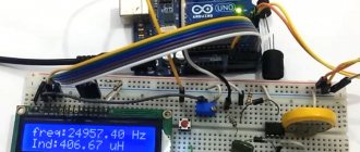
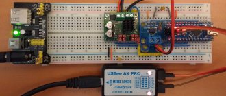
A capacitance and inductance meter - exactly what a standard multimeter cannot measure. Minimal functionality, but excellent accuracy and speed of measurements. You don't even need to calibrate! The meter arrived in a pact, wrapped in soft material. The equipment is spartan: a device and a mini-USB cord.
Crocodiles included and installed.
Buttons: Zero - if you move the probes until a stray capacitance appears, you can reset the readings. Hi.C - second, larger range of capacitance measurements (small by default) Hi.L - second, larger range of inductance measurements (small by default) L/C - selection of capacitance/inductance The fifth Func button does nothing. The instructions say that it is reserved for future updates. The measurement frequency is 500kHz for the first range and 500Hz for the second.
So, what it can do: Capacitance, ranges (0.01pF-10uF) and (1uF-100mF) Inductance, ranges (0.001uH-100mH) and (0.001mH-100H) ESR measurement, unfortunately, was not delivered. I am immediately attaching a link to the instructions: here You can get information about the accuracy of measurements from the instructions:
Optimistic? Enough. Let's check how it really is.
First, let's look at the hardware. On the right is the power switch:
On the back are USB and 5.5/2.1mm power connectors. Only 5 volts.
The manufacturer decided not to be a no-name, well done:
The device is easy to disassemble: unscrew the 4 screws on top and remove the display. The display is the most standard 1602, can be replaced without any problems.
I have no complaints about the quality of the board and wiring.
Except that the film capacitor is somewhat amusingly sealed:
And the inductor:
I don’t like the dangling heavy coil, so I immediately put it on a drop of hot glue:
The meter is based on the STM8S003 microcontroller. Yes, yes, this is NOT a clone of the Transistor Tester!
Nearby are LM311 comparators.
...and LM393:
I didn’t see any active electronics that control the power. So I don’t recommend exceeding the recommended 5 volts. The crocodiles in the kit are normally soldered. The wires are short, but for measuring capacitances and inductances this is justified.
The latest firmware 4.8 is installed (although the board says 4.7):
Beautiful pieces of hardware are, of course, good, but how can you check the accuracy? Of course, practically! Especially for Muska, I bought a bunch of parts with the minimum tolerances found. I even feel a little sorry for the person who collected this order for me, one coil capacitor at a time. =)
Analog multimeter
This type of multimeter displays measurement readings using an arrow, under which there is a display with different scales of values. Each scale displays the readings of a particular measurement, which are signed directly on the display.
But for beginners, such a multimeter will not be the best choice, since it is quite difficult to understand all the symbols that are on the display. This may lead to incorrect understanding of the measurement results.
How to check a fluorescent lamp starter
The process of checking fluorescent lighting devices involves not only checking the integrity of the spiral inside the light bulb, but also the operation of the acceleration and starting systems.
- capacitors that should not swell, deform or explode when exposed to excessive voltage in the electrical network;
- a light source bulb that cannot be dimmed.
The integrity of the capacitor is checked with a multimeter in ohmmeter mode with the maximum possible resistance measurement range.
If the tester reading is less than 2.0 MΩ, it can be assumed that the capacitor has unacceptable leakage current. As practice shows, the best option when carrying out independent repair work would be to completely replace all worn-out elements (starter and throttle valve) with new devices of a similar type.
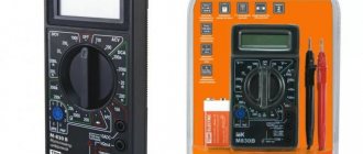
Digital multimeter
Unlike analogue ones, this multimeter allows you to easily determine the quantities of interest, while its measurement accuracy is much higher compared to pointer devices.
Also, the presence of a switch between different characteristics of electricity eliminates the possibility of confusing one or another value, since the user does not need to understand the gradation of the reading scale.
The measurement results are displayed on the display (in earlier models - LED, and in modern ones - liquid crystal). Due to this, the digital multimeter is comfortable for professionals and simple and easy to use for beginners.
How to check the choke of a fluorescent lamp?
The starter is an inductor wound on a ferromagnetic core with high magnetic permeability. It is an integral part of electromagnetic power supplies (EMPRA). In the ignition phase of the LDS, it, together with the starter, ensures heating of the cathodes, and then creates a high voltage pulse (up to 1000 V) to create a luminescent discharge in the cylinder due to its characteristic electromotive force (EMF) self-induction.
Once the starter has been removed from service, inductive reactance is used by the inductive reactance to maintain the discharge current through the LDS at the level required to continuously and stably ionize the gas-mercury mixture used in the cylinder. The amplitude of the inductance is such that the resistance of the AC inductor protects the coil electrodes from overheating and burning out.
The performance of the inductance of a fluorescent lamp can be checked by measuring the resistance using an ohmmeter. It is part of the electrician's combination instrument.
If you check the fluorescent lamp accelerator with a multimeter, you may find it in good condition, in which the measured active resistance matches the data in its data sheet, or you may encounter inconsistencies. After analyzing them, we can draw a conclusion about the nature of the detected defect. Short circuits are accompanied by an unpleasant odor and discoloration of the protective insulation. If there is an external manifestation or detection of a deviation of the measured resistance value from its nominal value, the inductance must be replaced.
Checking the inductance of a fluorescent lamp.
Inductance meter for multimeter
Despite the fact that it is rare to determine inductance when working with electronics, it is still sometimes necessary, and multimeters that measure inductance are quite difficult to find. In this situation, a special attachment to a multimeter will help, allowing you to measure inductance.
Often, for such a set-top box, a digital multimeter is used that is set to measure voltage with a measurement accuracy threshold of 200 mV, which can be purchased ready-made at any electrical and radio equipment store. This will allow you to make a simple attachment for a digital multimeter.
What is called inductive reactance
When an alternating voltage is applied to a coil, the current flowing through it changes according to the applied voltage. This causes a change in the magnetic field, which creates an electromotive force that prevents this from happening.
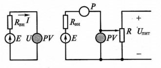
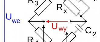
Measuring circuit
In such a circuit, there is a dependence of the electrical parameters of two types - conditional and inductive. They are designated R and XL respectively.
Under normal conditions, the power supply is assigned. However, on reactive elements it is zero. This is due to the constant reversal of the direction of alternating current.
During the oscillation period, energy is pumped into the coil twice and returned to the source the same number of times.
Definition of inductance
Set-top box assembly
You can assemble a tester attachment for a multimeter for measuring inductance without any problems at home, having basic knowledge and skills in the field of radio engineering and soldering microcircuits.
In the board circuit, you can use transistors KT361B, KT361G and KT3701 with any letter markers, but to obtain more accurate measurements it is better to use transistors marked KT362B and KT363.
These transistors are installed on the board in positions VT1 and VT2. At position VT3 it is necessary to install a silicon transistor with a pnp structure, for example, KT209V with any letter marking. Positions VT4 and VT5 are for buffer amplifiers.
Most high-frequency transistors are suitable, with h21E parameters for one not less than 150, and for another more than 50.
For positions VD and VD2, any high-frequency silicon diodes are suitable.
The resistor can be chosen MLT 0.125 or similar. Capacitor C1 is taken with a nominal capacity of 25330 pF, since it is responsible for the accuracy of measurements and its value should be selected with a deviation of no more than 1%.
Such a capacitor can be made by combining thermally stable capacitors of different capacities (for example, 2 at 10000 pF, 1 at 5100 pF and 1 at 220 pF). For other positions, any small-sized electrolytic and ceramic capacitors with an acceptable spread of 1.5-2 times are suitable.
Contact wires to the board (position X1) can be soldered or connected using spring clamps for “acoustic” wires. Connector X3 is intended for connecting the set-top box to a multimeter (frequency meter).
It is better to take shorter wires to bananas and crocodiles in order to reduce the influence of their own inductance on the measurement readings. In the place where the wires are soldered to the board, the connection should be additionally secured with a drop of hot-melt adhesive.
If it is necessary to regulate the measurement range, you can add a switch connector to the board (for example, for three ranges).
Calculation methods
There are several basic ways to determine the inductance of a coil. All formulas that will be used in calculations can be easily found in reference books or on the Internet. The entire calculation process is quite simple and will not be difficult for people with basic mathematical and physical knowledge.
Through current
This calculation is considered the simplest way to determine the inductance of a coil. The formula through current follows from the term itself. What is the inductance of the coil can be determined by the formula: L = Ф / I, where:
- L is the inductance of the circuit (in Henry);
- this is the magnitude of magnetic flux measured according to Weber;
- I is the current in the coil (in amperes).
This formula is only suitable for a single-turn circuit. If the coil consists of several turns, the total flux (total value) is used instead of the magnetic flux value. When the same magnetic flux passes through all the coils, then to determine the total value it is enough to multiply the value of one of them by the total number.
Finite Length Solenoid
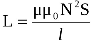
The solenoid is a long and thin coil whose winding thickness is much less than its diameter. In this case, calculations are made using the same formula as the current strength, only the magnitude of the magnetic flux will be determined as follows: Ф = µ0NS / l, where:
- µ0 is the magnetic permeability of the medium, determined from look-up tables (for air, which is the default value in most calculations, it is 0.00000126 henry/meter);
- N is the number of coil turns;
- S is the cross-sectional area of the chain, measured in square meters;
- l is the length of the solenoid in meters.
The self-inductance coefficient of the solenoid can also be calculated according to the method for determining the magnetic flux energy of the field. This is a simpler option, but it requires some values. Formula for determining inductance: L = 2W / I 2, where:
- W is the magnetic flux energy, measured in joules;
- I is the current strength in amperes.
Toroidal core coil
In most cases, the toroidal coil is wound on a core made of a material with high magnetic permeability. In this case, the infinite length straight solenoid formula can be used to calculate the inductance. It has the following form: L = N µ0 µS / 2 πr, where:
- N is the number of coil turns;
- µ—relative magnetic permeability;
- µ0—magnetic constant;
- S is the cross-sectional area of the core;
- π is a mathematical constant equal to 3.14;
- r is the average radius of the torus.
Sources
- https://NpfGeoProm.ru/teoriya-i-opyt/sposoby-izmereniya-induktivnosti.html
- https://sto82.ru/elektroteoriya/metody-izmereniya-induktivnosti.html
- https://TokMan.ru/praktika/metody-izmereniya-induktivnosti.html
- https://supereyes.ru/articles/multimetry-i-testery/rlc-izmeritel-kak-vybrat/
- https://DiesElit.ru/osnovy/kak-izmerit-induktivnost-katushki-multimetrom.html
- https://drova-pil.ru/novosti/proverka-induktivnosti-multimetrom.html
- https://TeploDom24.ru/teoriya-i-praktika/kak-izmerit-induktivnost-katushki.html
Multimeter attachment housing
The body can be made from a ready-made box of a suitable size or you can make the box yourself. You can choose any material, for example, plastic or thin fiberglass. The box is made to the size of the board, and holes are prepared in it for its fastening. Holes are also made for wiring connections. Everything is fixed with small screws.
The set-top box is powered from the mains using a power supply with a voltage of 12 V.
Р'ольшая РРЅС†Реклопедия Нефти Рё Газа
CC‚раница 1
RќR°R»РёС‡РеРµ RєРѕСЂРѕС‚РєРѕR·Р°РјРєРЅСѓS‚С‹S… RІРІРѕ‚РєРѕРІ RЅР° RїRѕR»СЋСЃР°С… двигат еля вызывает Р·РЅР °С‡РёС‚ельные электрические потери, величина РєРѕС‚РѕСЂС ‹С… РЅРµ зависит РѕС‚ нагрузки.
R'R»Р°РіРѕРґР°СЂСЏ этому SЃРІРѕР№СЃС‚РІСà дввгатель СЃ экранированн S‹РјРё полюсами может находиться РґР» оороткооо замыкаРхРјСЏ ( РѕР±РјРѕС ‚РєР° статора включена РІ сеть, Р° ротор неподвижен), что SѓРґРѕР±РЅРѕ РІ целом СЂСЏРґРµ случаев SЌРєСЃРїР»СѓР°С‚ации двигателя. [1]
RќР°Р»РёС‡РеРµ RєРѕСЂРѕС‚козамкнутыS… РІРІРѕ‚РєРѕРІ, RѕРґРЅР°РєРѕ, RїСЂРёРІРѕРґРёС ‚ Rє SѓРІРµР»РІРёС‡РµРЅРёСЋ времени RґРµР№СЃС‚РІРёСЏ SЂРµР»Рµ, RїРѕСЌС‚РѕРјСѓ RїСЂРёРјРµР Sение РёС … нежелательно для быстродействующих реле постоя РЅРЅРѕРіРѕ тока. Проверка катушек РЅР° отсутствРеРµ короткозамкнуS‚С ‹S… RІРІРѕРѕРІ производится SЃ RїРѕРјРѕС‰СЊСЋ SЃРѕРѕС‚ветствуюS‰ RyoS… RїSЂРёР±РѕСЂРѕРІ. [3]
RќР°Р»РёС‡РеРµ RєРѕСЂРѕС‚козамкнуS‚С‹S… РІРІРѕ‚РєРѕРІ РІ ССЃРѕ»РѕРІРѕРј S‚рансS „орматоре можно обнаружить, включРеРІ его РЅР° 1 — 1 5 часа РІ сеть RїРµСЂРµРјРµРЅРЅРѕРіРѕ S‚РѕРєР° Рё РѕСЃС ‚авив РїСЂРё SЌS‚РѕРј ненагруженными РІСЃРµ РІС‚РѕСЂРёС‡РЅС ‹Рµ обмотки. Если РїСЂРё этом трансформатор РЅРµ будет заметно нагреваться, то можно счит ать, что РІ нем отсутствуют короткозамкнутые РІРё S‚RєРё. RњРѕР¶РЅРѕ S‚акже Rезмерить RѕРјРјРµС‚СЂРѕРј RѕRјРј RѕRјРёС‡РµСЃРєРёРµ SЃРѕРїСЂРѕС‚Рё вления обмоток: уменыые -; РЅРѕРїСЂРѕС‚РевленоЏ обмотки RїРѕ SЃСЂР°РІРЅРµРЅРЅСЋ СЃ указываем S‹Рј заводом-изготовителем SЃРІРёРґРµС‚ельствует Рѕ наличРеРё короткого, замыкания S‡Р°СЃС‚Рё RѕР±РјРѕС‚РєРё. [4]
НаличРеРµ RєРѕСЂРѕС‚козамкнутыS… РІРІРѕ‚РєРѕРІ РІ обмотке R·РІСѓРєРѕР ІРѕР№ катушки SЃРєР°Р·С‹РІР°РµС‚СЃСЏ РІ значительном SѓРјРµРЅСЊС€РµРЅРёРё громкости RїРѕ сравнению S Ѓ исправным громкоговорителем того же типа. [5]
RќR°R»РёС‡РеРµ RєРѕСЂРѕС‚козамкнуS‚S‹S… RІРІРѕ‚РєРѕРІ РЅР° RјР°РіРЅРёС‚РѕРїСЂРѕРІРѕ РґРµ, потерь РІ магнитопроводе РЅР° вихревые S‚РѕРєРё Рё перемагнвЇРевание аналогично RїРѕСЏРІР»РµРЅРІР»РµРЅРёСЋ SЂРµР°РєС‚РёРІРЅРѕР іРѕ (РеРЅРґСѓРєС‚РеРІРЅРѕРіРѕ) RјР°РіРЅРёС‚РЅРѕРіРѕ SЃРѕРїСЂРѕС‚ивления РІ магно ‚РЅРѕР№ цепи. RђРєС‚РёРІРЅРѕРµ RјР°РіРЅРёС‚РЅРѕРµ SЃРѕРїСЂРѕС‚ивленве RјР°РіРЅРёС‚РѕРїСЂРѕ-РІРѕР ґР° определяется магнитной проницаемостью RјР°С‚ериала. [7]
RќR°R»РёС‡РеРµ RєРѕСЂРѕС‚РєРѕR·Р°РјРєРЅСѓS‚С‹S… RІРІРѕ‚РєРѕРІ RЅР° RїRѕR»СЋСЃР°С… двигат еля вызывает Р·РЅР °С‡РёС‚ельные электрические потери, величина РєРѕС‚РѕСЂС ‹С… РЅРµ зависит РѕС‚ нагрузки.
R'R»Р°РіРѕРґР°СЂСЏ этому SЃРІРѕР№СЃС‚РІСà дввгатель СЃ экранированн S‹РјРё полюсами может находиться РґР» оороткооо замыкаРхРјСЏ ( РѕР±РјРѕС ‚РєР° статора включена РІ сеть, Р° SЂРѕС‚РѕСЂ неподвижен), что SѓРґРѕР±РЅРѕ РІ SЂСЏРґРµ SЃР»СѓС‡Р°РµРІ SЌРєСЃРїР»S ѓР°С‚ацРеРё двигателя. [8]
НаличРеРµ RєРѕСЂРѕС‚козамкнутых РІРІРѕ‚РєРѕРІ RѕR±RјРѕS‚РєРё SЌР»РµРєС‚СЂР ѕРјР°РіРЅРёС‚Р° характеризуется SЂРµР·РєРёРј SѓРјРµРЅСЊС€РµРЅРёРµРј SЃРѕРїСЂРѕС‚ивленвмноговвитковой Р ѕР±РјРѕС‚РєРё переменному S‚РѕРєСѓ.
РќР° магни-топровод насажена катушка возбуждения /, РїРѕ Р єРѕС‚РѕСЂРѕР№ РїСЂРѕС…РѕРґРёС‚ переменный ток . нспытуемая катушка 2 надевается РЅР° второй сердеч РЅРёРє магнитопровода.
[9]
РџСЂРё наличРеРё короткозамкнутых ввитков РІРѕ вторичной обмотке трансформатора токР° его характеристРеРєР° намагничРевания SЃРЅРёР¶Р°РµС‚СЃСЏ, как РїР ѕРєР°Р·Р°РЅРѕ РЅР° СЂРёСЃ.
14 - 9, что может быть RѕР±РЅР°СЂСѓР¶РµРЅРѕ RїСЂРё SЃСЂР°РІРЅРµРЅРёРё RїРѕР»СѓС‡Р µРЅРЅРѕР№ характеристики СЃ С …арактеристикой, снятой ранее, или СЃ характеристикам Рё однотипных трансформаторов тока. [10]
РџСЂРё наличРеРё короткозамкнуS‚С‹S… ввитков S…арактеристи РєР° намагничРевания SЂРµР·РєРѕ SЃРЅРёР¶Р °РµС‚СЃСЏ, как показано РЅР° СЂРёСЃ.
216. SРЅРѕР№ характеристРеРєРё SЃ S…Р °СЂР°РєС‚еристикой, снятой ранее, или СЃ характеристиками RѕРґРЅРѕС‚Репных С‚СЂР°РЅСЃС„РѕСЂРјР°С ‚РѕСЂРѕРІ тока. [12]
РџСЂРё наличРеРё короткозамкнуS‚ых внтков стальная пласS ‚РёРЅР°, находящаяся над пазом, начРенает вибрировать. РџСЂРё коротком замыкании или обрыве обмотки SЏРєРѕСЂСЊ заменяют. [14]
РџСЂРё наличРеРё короткозамкнутых ввитков РЅР° SЌРєСЂР°РЅРµ RїРѕСЏР ІР»СЏСЋС‚СЃСЏ РґРІРµ кривые, РѕРґРЅР° над нулевой линиеРNo., другая РїРѕРґ ней. [15]
Страницы: 1 2 3 4
Setting up an inductance meter
In order to calibrate the attachment for measuring inductance, you will need several induction coils with known inductance (for example, 100 μH and 15 μH).
The coils are connected one by one to the attachment and, depending on the inductance, the trimmer resistor slider on the multimeter screen sets the value 100.0 for a 100 µH coil and 15 for a 15 µH coil with an accuracy of 5%.
Using the same method, the device is configured in other ranges. An important factor is that accurate test inductor values are required to accurately calibrate the attachment.
An alternative method for determining inductance is the LIMP program. But this method requires some preparation and understanding of how the program works.
But in both the first and second cases, the accuracy of such inductance measurements will not be very high. This inductance meter is not suitable for working with high-precision equipment, but for home use or for radio amateurs it will be an excellent assistant.
Lc meter circuit on a microcontroller
Setup and features
The heart of the device is the PIC18F2520 microcontroller. For stable operation of the generator, it is best to use non-polar or tantalum capacitors such as C3 and C4. You can use any relay that matches the voltage (3-5 volts), but preferably with the lowest possible contact resistance in the closed position. For sound, a buzzer without a built-in generator or a regular piezoelectric element is used.
When you first start the assembled device, the program automatically starts the display contrast adjustment mode. Use buttons 2/4 to set the contrast to an acceptable level and press OK (3). After completing these steps, the device should be turned off and on again. The menu has a “Settings” section for some settings for the operation of the device. In the “Capacitor” submenu, you must specify the exact value of the calibration capacitor used (C_cal) in pF. The accuracy of this estimate directly affects the accuracy of the measurement. You can check the operation of the generator itself using a frequency meter at test point “B”, but it is better to use the frequency control system already built into the “Generator” submenu.
By selecting L1 and C1, it is necessary to obtain stable frequency readings in the range of 500-800 kHz. High frequency has a positive effect on measurement accuracy; At the same time, as the frequency increases, the stability of the generator may deteriorate. It is convenient to monitor the frequency and stability of the generator, as I said above, in the “Oscillator” menu section. If you have an external calibrated frequency meter, you can calibrate the LC meter frequency meter. To do this, connect an external frequency meter to test point “B” and use the +/- buttons in the “Oscillator” menu to select the constant “K” so that the readings of both frequency counters coincide. For the battery status indication system to work correctly, you need to set up a resistive divider on resistors R9, R10, then install jumper S1 and write the values in the fields of the “Battery” section.
Carrying out inductance measurements
After assembly, the multimeter attachment must be tested. There are several ways to check your device:
- Determination of the inductance of the measuring attachment. To do this, you need to short-circuit two wires intended for connection to the inductive coil. For example, with a length of each wire and jumper of 3 cm, one turn of the induction coil is formed. This turn has an inductance of 0.1 - 0.2 μH. When determining inductance above 5 μH, this error is not taken into account in the calculations. In the range of 0.5 - 5 µH, when measuring, it is necessary to take into account the inductance of the device. Readings less than 0.5 µH are approximate.
- Measuring an unknown inductance value. Knowing the frequency of the coil, using a simplified formula for calculating inductance, you can determine this value.
- In the case when the response threshold of silicon pn junctions is higher than the amplitude of the measured electrical circuit (from 70 to 80 mV), it is possible to measure the inductance of the coils directly in the circuit itself (after de-energizing it). Since the set-top box’s own capacitance is of great importance (25330 pF), the error in such measurements will be no more than 5%, provided that the capacitance of the measured circuit does not exceed 1200 pF.
When connecting the set-top box directly to the coils located on the board, 30 centimeters long wiring with clamps for fixation or probes is used. The wires are twisted at the rate of one turn per centimeter of length. In this case, the inductance of the set-top box is formed in the range of 0.5 - 0.6 μH, which also must be taken into account when measuring inductance.
Typical examples of using an LCR meter and a transistor tester for checking radio components
Resistors are the most common type of radio components
Wirewound resistors with different power ratings
| If there are no problems with common values, measuring low resistance resistors can complicate the task. With a conventional multimeter you can often measure normal resistance of the order of 1-2 ohms and higher; if lower, then the resistance of the wires, probes and low resolution begin to have a strong effect. Even the fairly accurate UNI-T UT61E has a measurement resolution in this mode of only 10 mOhm, while even an inexpensive LCR meter has a minimum resolution of 0.1 mOhm. | Digital multimeter UNI-T UT61E high accuracy with the ability to connect to a PC to delete logs |
Accordingly, if using a multimeter it is possible to relatively accurately measure resistors with a resistance of 0.05-0.1 Ohm, then when measuring 10 mOhm, practically nothing can be measured; for comparison, below is the measurement of two resistors with a nominal value of 1 and 2.2 mOhm.
Difference between multimeter and RLC tester readings when measuring low resistance resistors
Low resistance measurements are often required when testing, sizing or manufacturing current sensing shunts. An alternative option for measuring voltage drop, but requires an adjustable power supply, ammeter, voltmeter.
The current shunt is a low resistance resistor which is a low resistance resistor
The ability to measure low resistance is also useful for detecting problems such as marking errors, especially low resistance resistors.
The resistor on the left is labeled as 0.1 ohm, on the right as 0.22 ohm, but in reality they have almost the same resistance. Such mistakes can sometimes be very costly.
Before installing or soldering a resistor in a circuit, check its resistance. Make sure the nominal and actual values of the resistor are the same
Transistors
Measuring low resistances will help evaluate the originality of field-effect transistors. Currently, more and more counterfeit transistors and transistors with altered markings are appearing on the market. While simply measuring resistance doesn't give you the full picture, it does give you a quick idea of what's in front of you.
For the test, in addition to the device, a 9-volt battery is sufficient. Datasheets often refer to a gate voltage of 10 volts, but this is not relevant in this case. In addition, it is correct to measure the drain-source resistance by current; it is usually indicated in the documentation, but for this you need at least a laboratory power supply.
To test the transistor: we connect test probes to the drain and source terminals (usually the center and right), and apply 9 volts to the outer terminals. A constant voltage application is not required, just charging the gate capacitor is enough, but you need to be careful not to accidentally connect the battery to the tester probes. You can also “load” the transistor first, and only then connect the probes.
Capacitors
Capacitors are used somewhat less frequently, but have their own characteristics. For example, unlike resistors, they are much more susceptible to aging, especially when it comes to electrolytic capacitors installed in switching power supplies, motherboard converters, etc.
The ESR of capacitors is of particular importance. When a capacitor dries with almost no loss of capacity, its internal resistance increases significantly.
This cannot be diagnosed with a regular multimeter; you can change everything, but this is not always convenient, often difficult or expensive. Additionally, RLC meters often allow measurements to be made without desoldering the component, although this of course depends on the wiring diagram.
- Most multimeters measure the capacitor as ideal, that is, without taking into account its features, sometimes this is enough, sometimes not.
- More sophisticated devices can separate the capacitor from its internal resistance and measure these parameters separately.
- The equivalent circuit of a capacitor looks much more complex - all these parameters can be measured, but this is a completely different class of devices that ordinary radio amateurs usually do not need.
Equivalent series circuit, where R is the electrical resistance of the capacitor insulation, responsible for the leakage current, and the equivalent series resistance; L—equivalent series inductance; - capacitor capacity
For example, a comparison of two capacitors, cheap and branded Chinese. Although accurate, a conventional multimeter considers them almost identical, showing only a slight difference in capacitance. But if you connect the capacitors to an LCR meter, you can see that the difference in their internal resistance is almost 5 times! If you plan to use capacitors when switching power supplies, it is this resistance difference that will affect heating and, as a result, the service life and characteristics of the power supply. Capacitors with high internal resistance cannot effectively suppress peaks.
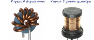
Chokes and inductors
Reactors, transformers, and winding units in general, unlike capacitors and resistors, are even more difficult to control, and typically a multimeter can measure inductance.
The main characteristic of the narrowing is inductance, that is, a coefficient that determines the dependence of the rate of change of electric current on the voltage on the coil
An impedance meter facilitates the manufacture of winding units, as well as the search for short circuits between turns. Compared to a good component or a component of known rating, you can tell that the transformer or inductance is faulty because its inductance will change greatly.
Electrical monitoring of inductors includes detection of turn short circuits (short circuits between winding turns). If there is an interturn circuit in the studio winding, its inductance will drop sharply.
Typically, there are indicators to detect shorted loops, but an impedance meter will also detect this problem. For example, on the left there is a working transformer, on the right it is the same, but with a shorted turn. It can be seen that the winding inductance has become significantly smaller, and the turn also affected the result of measuring the active resistance of the winding.
Comparison of the inductance of a working transformer and a closed-loop transformer