A home electrical network is a complex system of electrical installations and devices connected by electrical conductors. Wires are connected in electrical panels, junction boxes and device housings.
Let's look at how to connect wires without soldering using special clamps and terminals so that the switching is as reliable as possible and meets safety requirements. For this purpose, we provide 4 detailed instructions with the best ways to connect electrical wires.
We will also supplement our material with useful installation tips from experienced electrical installation specialists.
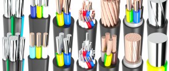
Types of cables for connection
The most common cable for home electrical wiring is a PVA connecting cable, consisting of two insulating layers. Copper strands, stranded, twisted along the central axis. The wire is flexible, making it great for a variety of connections.
The voltage of connected devices must be up to 380 Volts.
The cross section is selected depending on the load:
- for a current of 6 A, PVA with a cross section of 0.75 mm is used;
- for 10 Amperes - the cross-section is 1 mm;
- for currents of 16 A – 1.5 mm.
In addition to the PVS wire, for connection there are multi-core cables ShVVP, PUGNP, PRS, KG. They are used less frequently for home wiring than PVS.
GOST classifications and requirements
Wire connectors are any devices that serve to close/open an electrical circuit. These can be electrical installation products - sockets, switches, as well as metal bars and plates, lugs, terminals and terminal blocks - blocks with several sockets.
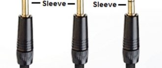
We will focus on connectors in a narrower sense - on elements that create detachable and non-separable connections and ensure their reliability and functionality - that is, on all kinds of terminals, terminal blocks and sleeves.
The simplest example of a lug for a stranded wire. The terminal is a metal sleeve-tube fixed at the end of the conductor using crimping pliers
Terminals are called both metal elements for decorating the ends of single- and multi-core wires, and small plates inside connecting devices - sockets, terminal blocks, patch panels.
The terminals differ in material, shape and size, but are similar in purpose - they provide mechanically strong switching of two or more wires, without electrical losses and installation difficulties
The classification of electrical connectors is presented in GOST 10434-82 , which provides information on the division into classes (1, 2, 3) and groups (A, B). Also, according to standards, contact connections are divided into detachable and permanent, requiring stabilization or working without it.
Some recommendations may be useful not only to professionals, but also to home craftsmen who install their own electrical wiring.
For example, it talks about the most preferred methods of connecting aluminum plates - soldering or welding and aluminum tips - crimping or welding.
What is the best way to reliably connect two cables together?
Methods of connecting cables that require equipment and skills in the field of electrical engineering:
- soldering;
- welding;
- crimping with sleeves.
Simple connection methods that do not require tools or knowledge:
- connection using terminal blocks;
- spring clamps;
- PPE caps;
- bolted connection.
The choice of connection method depends on the characteristics of the wires. It is necessary to take into account the type and material of the core, the number of wires, and operating conditions.
Aluminum
Aluminum wires can also be connected using any method, but with some special features. When connecting, the metal must be manually stripped of insulation.
Copper and aluminum wires cannot be connected directly. The connection point becomes very hot and over time the contact weakens. Therefore, it is better to use terminal blocks, wago, bolt connection or special branch clamps.
Copper
Copper wire can be connected using terminal blocks, Wago clamps (necessarily using special paste), using a bolt, or soldering.
Crimping
For this method, special tubular sleeves or lugs are used, with which the wires to be connected are crimped and crimped. The essence of the method is the joint deformation of the sleeve and the cores inserted into it. When deformed, the sleeve contracts and puts pressure on the conductive surfaces. The conductors engage in mutual adhesion, which ensures reliable electrical contact.
The advantage of such a connection is its reliability, and also the fact that it can be classified as “set and forget”; it does not require maintenance.
But along with the positive aspects, crimping also has a number of disadvantages. First, a special tool is required (a crimping press or mechanical or hydraulic pliers). Secondly, the quality of the connection directly depends on the correctly selected sleeve (it is selected depending on the number of cores being connected and their cross-section).
Before connecting two wires using crimping, they are not only stripped of insulation, but also lubricated with a special paste. Aluminum is treated with quartz-vaseline paste; it removes the oxide film and prevents it from appearing again. For copper conductors, quartz impurities are not needed; technical petroleum jelly is sufficient. It is needed to reduce friction. Lubrication also minimizes the risk of damage to the cores during deformation.
Next, the cores must be inserted into the sleeve until they mutually stop, and alternate crimping is performed on both sides. The pressed joint is insulated using insulating tape, varnished cloth or a thermal tube.
How to connect wires with sleeves is shown in these videos:
Connecting electrical wires by twisting
Until recently, twisting was the most common method of connecting wires when doing electrical wiring; due to its accessibility, all it took was a knife and pliers. But, according to statistics, twisting is an unreliable way to connect conductors.
According to the electrical installation rules (PUE), twisted connections when installing electrical wiring are prohibited. But, despite the noted disadvantages, the twisting method is currently widely used. Connecting conductors of low-current circuits by twisting, subject to certain rules, is quite justified.
The photo on the left shows how twisting is unacceptable. If one conductor is twisted around another, the mechanical strength of such a connection will be insufficient. When twisting wires, you must make at least three turns of wires around each other. In the middle photo, the twisting is done correctly, but a copper conductor is twisted with an aluminum one, which is not permissible, since when copper comes into contact with aluminum, an emf of more than 0.6 mV occurs.
In the photo on the right, the twisting of copper and aluminum wires is done correctly, since the copper wire is tinned with solder before twisting. You can twist several wires together at once; in a junction box, sometimes up to 6 conductors are twisted, wires of different diameters and from different metals, a stranded wire with a single-core wire. Only the stranded wire needs to be made single-core by first soldering it with solder.
Precautionary measures
Soldering without special tools at home is a dangerous task that requires precautions.
It is imperative to take care of insulation if live wires are to be connected. You cannot carry out work touching them with bare hands.
If possible, ensure that devices are disconnected from the mains or other power source.
When using hot soldering methods at home using an open flame, the list of precautions will be as follows.
- Do not leave a flame source unattended.
- Prepare and place fire extinguishing equipment in the freely accessible area.
- Do not light a fire near flammable objects, pressure cylinders, including aerosol substances.
- It is better to protect your hair with a hat or bandana. Choose clothes from non-flammable materials that fit tightly to the body.
- Wear fire-resistant gloves while performing work. Choose shoes with heat-resistant soles.
- Avoid the presence of children, people with disabilities, and animals nearby.
- Ensure the drainage of accumulated combustion products from the premises.
By following these guidelines, you can safely perform hot soldering using an open flame.
What is wire twisting and why is it dangerous?
Several decades ago, when the load on electrical wiring was not so great, such a connection was popular. Moreover, experienced craftsmen taught me, then a young electrician, to first thoroughly strip the metal cores, twist them tightly, and crimp them with pliers.
The length of this twist had to be created on the order of 10 cm to ensure good electrical contact, as shown in the lowest example. And they would reject anything higher, despite its beauty.
Inside closed, dry rooms, such twists worked for years and decades. However, many electricians violated the technology and created poor-quality contact.
In addition, in a humid environment, the metal oxidizes. The electrical resistance of its transition surface layer deteriorates. This leads to increased heating of the cores and premature damage to the insulation.
Therefore, modern rules, in particular the PUE, prohibit simple twisting of wires, no matter how beautifully and reliably it is done.
Particularly dangerous are twists of aluminum wires, as well as cores made of different metals - copper and aluminum.
This is due to the high ductility of soft aluminum and its high ability to create, under the influence of atmospheric oxygen, an outer layer of oxides that protects the internal structure of the metal. This film reduces conductivity.
When currents flow with increased loads, aluminum, which has a high coefficient of linear expansion, heats up, increasing its volume. After cooling, it contracts, breaking the tightness of the joint.
Each heating and cooling cycle degrades the electrical performance of the strand. In addition, copper and aluminum work as a galvanic couple, and these are additional chemical reactions with the formation of surface oxides.
Recommendation: wherever you find a simple twist, get rid of it. Reinforce it by soldering, welding, crimping or any other approved method.
Terminal blocks and terminal blocks: how to distinguish between durable and unreliable structures
Most often, terminal blocks are used in lighting circuits with relatively small loads. They are made from different materials and different shapes.
The plastic-covered housing has holes for installing stripped wires and a slot for the head of the clamping screw.
All simple terminal blocks are made of cheap transparent polyethylene with inserts of thin brass sockets with screw terminals, as shown at the very top of the picture.
Their disadvantages:
- thin-walled brass easily bursts when the metal core is normally clamped with a screw;
- weak threads on the nut cannot withstand the load when tightening the wire;
- the lower edge of the screw is made with sharp edges, which greatly deform the wire, even when crimped into NShVI lugs.
Working with such structures is difficult. They are not reliable, break, and create excessive heating of the wiring.
After connecting each wire to the screw connection, it is necessary to check the quality of the connection: take the terminal block in one hand and the wire in the other. A sharp pull should not destroy the contact created.
Higher quality terminal blocks are made of durable, smooth plastic with thick metal tubes and clamping plates that do not crush the metal cores. They have strong screws and nuts.
With their help, it is convenient to connect wires made of different metals, for example, connecting aluminum apartment wiring to flexible copper conductors of an LED chandelier or lamp. But you shouldn’t neglect NShVI tips.
Previously, terminals with a screw clamp under a ring were common, which ensured tighter contact of the core with the terminal
When installing, pay attention to the correct installation in the direction of tightening the screw.
The squeezing force should compress the ring inward, and not bend outward, weakening the contact.
When connecting without a ring with a straight section, the metal cores are placed closer to the thread, and their position is monitored when clamping. When tightened, it should be well secured and not fall out. Checked by pulling.
In all terminal blocks, without exception, the condition of the wire insulation is monitored. It should not get under the thread anywhere or interfere with the creation of electrical contact.
Terminal connections are permitted by all electrical installation regulations. But, they require periodic inspection and tightening of screw terminals approximately every two years in circuits with permissible loads. After overloads and short circuits they should be inspected immediately.
Connecting electrical wires by soldering
The connection of copper wires with high-quality soldering is the most reliable and is practically not inferior to a solid wire. All of the above examples of twisted wires, except for aluminum and tinsel, when tinning the conductors before twisting and then soldering them with solder, will be reliable on a par with solid wires. The only drawback is the extra labor involved, but it's worth it.
If you need to connect a pair of wires and the twisted conductors must be directed in different directions, then a slightly different type of twist is used.
By splicing two pairs of double wires in the manner described below, it is possible to obtain a compact and beautiful connection by twisting both single-core and stranded pairs of conductors. This twisting method can be successfully used, for example, when splicing broken wires in a wall, extending a wire when moving a socket or switch from one place on the wall to another, when repairing or extending the length of a carrying cable.
To obtain a reliable and beautiful connection, it is necessary to adjust the lengths of the ends of the conductors with a shift of 2-3 cm.
Remove the insulation from the ends of the wires.
Twist the conductors in pairs. With this type of twisting, two turns are enough for a single-core wire, and five for a multi-core wire.
If you plan to hide the twists under plaster or in another inaccessible place, then the twists must be soldered. After soldering, you need to go over the solder with sandpaper to remove any sharp solder icicles that could pierce the insulation and stick out from it. You can do without soldering if the connection is accessible and there is a small current flowing through the conductors, but the durability of the connection without soldering will be much lower.
Due to the shift of the twisting points, there is no need to insulate each of the connections separately. We attach a strip of insulating tape on both sides along the conductors. Finally, you need to wind three more layers of insulating tape. According to the requirements of the Electrical Safety Rules, there must be at least three layers.
Wires spliced and soldered in the manner described above can be safely laid in the wall and plastered on top. Before installation, it is advisable to protect the connection with a vinyl chloride tube placed in advance on one of the pairs of wires. I have done this many times, and the reliability has been confirmed by time.
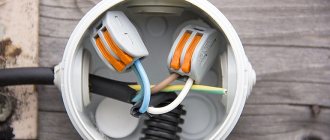
Connecting sockets
Usually a separate line is allocated to the sockets. The box contains three cables of two or three conductors. Each wire is painted a different color. As a rule, brown is the phase, blue is the neutral conductor, and the yellow-green wire is ground. One way or another, in the box all the wires are connected by color, forming groups.
Once the conductors are separated by color, they are folded, stretched, and adjusted to the same length. Don't cut too short - leave a 100mm margin so that you can re-connect if necessary. Having chosen the appropriate connection method, you need to connect the wires.
In old houses there is no grounding, which means there will be only two wires. Sometimes the wires in the cable are the same color. To determine where the phase is and where the zero is, you need to use an indicator screwdriver to determine the phase.
Terminals
Terminal blocks for connecting wires provide one undeniable advantage: they can connect cores of different metals. Both here and in other articles, we have repeatedly reminded that twisting aluminum and copper wires together is prohibited. The resulting galvanic couple will result in corrosion processes and destruction of the connection. And it doesn’t matter how much current flows at the connection. Late or early, the twist will still start to heat up. Terminals are the way out of this situation.
Terminal block
The simplest and cheapest solution is polyethylene terminal blocks. They are not very expensive and are sold in every electrical goods store.
The polyethylene frame is designed for several cells, inside each there is a brass tube (sleeve). The ends of the connected wires must be inserted into this sleeve and clamped with two screws. It is very convenient that as many cells are cut from the block as it is necessary to connect pairs of wires, for example, in one junction box.
But not everything is so smooth, there are also disadvantages. At room conditions, aluminum begins to flow under screw pressure. You will have to periodically inspect the terminal blocks and tighten the contacts where the aluminum conductors are fixed. If this is not done in a timely manner, the aluminum core in the terminal block will become loose, lose reliable contact, and, as a result, spark and heat up, which can result in a fire. Such problems do not arise with copper conductors, but it would not be superfluous to periodically inspect their contacts.
Terminal blocks are not intended for connecting stranded wires. If stranded wires are clamped into such connecting terminals, then when tightening the screw under pressure, the thin wires may partially break, which will lead to overheating.
In cases where it becomes necessary to clamp stranded wires into a terminal block, it is imperative to use auxiliary pin lugs. It is very important to choose the correct diameter so that the wire does not jump out later. The stranded wire must be inserted into the lug, crimped using pliers and secured in the terminal block.
As a result of all of the above, the terminal block is an ideal option for single-core copper wires. With aluminum and stranded ones you will have to comply with a number of additional measures and requirements.
How to use terminal blocks is shown in this video:
Terminals on plastic blocks
Another very convenient wire connector is a terminal on plastic blocks. This option differs from terminal blocks in that it has a smooth metal clamp. The clamping surface has a recess for the wire, so there is no pressure on the wire from the screw being tightened. Therefore, such terminals are suitable for connecting any wires.
Everything about these clamps is extremely simple. The ends of the wires are stripped and placed between the contact and pressure plates.
Such terminals are additionally equipped with a transparent plastic cover, which can be removed if necessary.
Self-clamping terminals
Wiring installation using such terminals is simple and quick.
The wire must be inserted into the hole to the very end. There it is automatically fixed using a pressure plate, which presses the wire to the tinned busbar. Thanks to the material from which the pressure plate is made, the clamping force does not weaken and is maintained all the time.
The internal tinned busbar is made in the form of a copper plate. Both copper and aluminum wires can be fixed in self-clamping terminals. These terminals are disposable.
And if you want clamps for connecting reusable wires, then use terminal blocks with levers. They lifted the lever and inserted the wire into the hole, then fixed it there by pressing it back. If necessary, the lever rises again and the wire protrudes.
Try to choose clamps from a manufacturer that has proven itself well. The clamps have especially positive characteristics and reviews.
The advantages and disadvantages are described in this video:
PPE caps – connecting insulating clips
Now let’s look at the PPE spring caps in detail. These clamps have not gained such great popularity among electricians and ordinary people, and there are reasons for this.
Terminal clamp
This device will not be a block, but depending on the model, it can connect up to 8 conductors in one housing.
The outer material is plastic, which has a number of features:
- Does not support combustion even when exposed to open fire;
- Has a high melting point;
- Withstands voltages from 300 to 600 V, which indicates high insulating properties;
- It has high mechanical strength and reliably protects the connection from any damage.
The cap has a cone shape. The outside is corrugated or has two blades for ease of use.
A compression spring of the same shape is installed inside. As was written above, its edges are sharpened in a special way, which allows you to securely fix cores of different sizes.
If we compare PPE with Vago terminals, they will have a couple of obvious disadvantages:
- Inability to simultaneously connect aluminum and copper wires.
- Complicated installation that requires special processing of the wires - it is necessary to thoroughly clean the insulation without protruding even a millimeter of the bare part of the wire beyond the cap body.
- An accurate selection of the cap model for the wire cross-section is required, since the best contact will be in the narrowest place, and if the wires are too thin, there will be increased resistance at the connection point, as when twisting the wires.
- Sufficient force is required to ensure good contact between the conductors.
- The cores must be strictly the same diameter.
- For multi-core wires, this solution will not be the best, since partial damage to thin wires is possible.
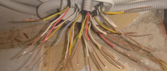
PPE caps in the junction box
The cap is installed in the following sequence:
- The wires are exposed from insulation to a length corresponding to the length of the corrugation on the cap;
- Their ends are connected in parallel, without preliminary twisting.
- The cap is placed on top and rotated with force clockwise.
- When connecting three wires, a preliminary twist is made, after which its tip is bitten off.
How PPE works
The following video will show how to install PPE caps.
There are five types of PPE terminals in total, the difference between which can be seen in the following image.
The difference between PPE caps
Interesting to know! PPE 5 can be used to connect 8 cores with a cross section of 2.5 mm2.
The table also shows the color coding of the models. The majority of manufacturers adhere to it, but there is no single standard, so there may be differences, so be careful when purchasing.
Pay attention to the product labeling (PPE 1 1.0-3.0 and similar). It will help you accurately select the product for the cross-section of your wire.
The first digit of the marking indicates the type of housing, the rest indicate the permissible range of cross-sections.
Welding
In order for the connection of electrical wires to be as reliable as possible, the considered twisting method must be subsequently secured by welding. It is similar to soldering, only now a welding machine is used instead of a soldering iron.
Positive sides
This method is most preferable to all others, since it meets all regulatory requirements in terms of reliability and quality.
The welding method is based on contact heating of the ends of the wires with a carbon electrode until a ball (contact point) is formed. This ball is obtained as a single unit from the fused ends of all connected cores, which ensures safe and reliable contact; it will not weaken or oxidize over time.
Negative sides
The disadvantage of welding is that such work requires certain knowledge, experience, skills and special equipment; you often have to turn to specialists.
Installation
In order to connect wires using welding, you will need the following devices, tools and materials:
- welding inverter with a power of at least 1 kW, its output voltage must be up to 24 V;
- carbon or graphite electrode;
- goggles or eye mask;
- welding leather gloves to protect hands;
- a mechanic's knife or stripper for removing the insulating layer from conductors;
- sandpaper (for cleaning the conductive surfaces to be connected);
- insulating tape for further insulation of the welding joint.
The sequence of work is as follows:
- Free each connected wire from 60-70 mm of insulation.
- Sand the exposed wires until they are shiny using sandpaper.
- Twist, after biting, the length of its ends should be at least 50 mm.
- Attach grounding clamps to the top of the twist.
- To ignite the arc, bring the electrode to the bottom of the twist and lightly touch the connected wires with it. Welding happens very quickly.
- It turns out to be a contact ball, give it time to cool, and then insulate it with tape.
As a result, an almost solid wire is obtained at the end, that is, the contact will have the lowest transition resistance.
If you connect copper wires in this way, then choose a carbon-copper electrode.
I would like to recommend that if you purchase a welding machine (it will be useful not only for connecting wires, but also for many other purposes), then choose the inverter option. With small dimensions, weight and electrical energy consumption, it has a wide range of welding current adjustment and produces a stable welding arc. And this is very important to be able to regulate the welding current. If you choose it correctly, the electrode will not stick and the arc will hold steady.
Watch how welding is done in this video:
We looked at the main types of wire connections. Now let’s briefly talk about methods that are used less frequently, but also guarantee quality and reliability.
Scotch-lock
Couplings of this type are for one-time use. Used for wires with low operating currents (telephone lines or wires for low-power LED lamps).
These clamping couplings make connections by means of a mortise contact. The wires don't even need to be stripped before connecting. They are inserted directly into the insulating layer into adhesive tape and crimped with pliers. The plate, which has cutting contacts, cuts into the insulating layer, due to which contact between the cores occurs.
In addition to the fact that stripping of cores is not required, adhesive locks have a number of other advantages:
- low cost;
- versatility;
- no special devices are needed, crimping is done with ordinary pliers;
- waterproof (there is a hydrophobic gel inside the coupling, which protects the contact connection from moisture and corrosion).
- If the Scotch-lock coupling needs to be replaced, it is simply cut out and a new one is installed in its place.
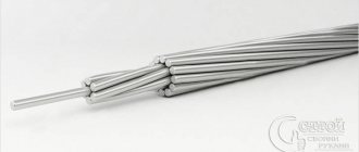
Sleeves
When powerful clamps for several wires are needed, sleeves are used. They are a tinned copper tube or a flat tip with a hole made for fastening.
All connected wires must be inserted into the sleeve and crimped using a special crimper device (crimping pliers). This wire clamp has a number of positive aspects:
- It is very convenient to use lugs with holes when there is a need to secure wire assemblies to housings with screws.
- Crimping at the connection does not increase the resistance.
As you can see, there are a lot of wire clamps, each with its own advantages and disadvantages. Choose based on which wires you need to connect and where the connection will be located. But do not forget that the most important thing in electricity is reliability and safety.
Wago
The next type is Wago terminal blocks. They also come in different sizes, and for different numbers of connected wires - two, three, five, eight.
They can connect both monocores and stranded wires together.
For stranded ones, the clamp must have a latch-flag, which, when open, easily allows you to insert the wire and clamp it inside after latching.
According to the manufacturer, these terminal blocks in home wiring can easily withstand loads of up to 24A (lights, sockets).
There are some compact specimens also available for 32A-41A.
Here are the most popular types of Wago clamps, their markings, characteristics and what cross-section they are designed for:
There is also an industrial series for cable cross-sections up to 95mm2. Their terminals are really large, but the principle of operation is almost the same as that of small ones.
When you measure the load on such terminals, with a current value of more than 200A, and at the same time you see that nothing is burning or heating, many doubts about Wago products disappear.
If you have original Vago clamps, and not a Chinese counterfeit, and the line is protected by a circuit breaker with a correctly selected setting, then this type of connection can rightfully be called the simplest, most modern and convenient to install.
Violate any of the above conditions and the result will be quite natural.
Therefore, there is no need to install wago at 24A and at the same time protect such wiring with a 25A automatic. In this case, the contact will burn out if overloaded.
Always choose the right terminal blocks for your car.
As a rule, you already have automatic machines, and they primarily protect the electrical wiring, and not the load and the end consumer.
ZVI
There is also a fairly old type of connection, such as terminal blocks. ZVI – insulated screw clamp.
In appearance, this is a very simple screw connection of wires to each other. Again, it comes in different sections and different shapes.
Here are their technical characteristics (current, cross-section, dimensions, screw torque):
However, ZVI has a number of significant disadvantages, due to which it cannot be called the most successful and reliable connection.
Basically, you can only connect two wires to each other in this way. Unless, of course, you specifically choose large pads and shove several wires there. What to do is not recommended.
This screw connection works well for monocores, but not for stranded flexible wires.
For flexible wires, you will have to press them with NShVI lugs and incur additional costs.
You can find videos online where, as an experiment, transition resistances on different types of connections are measured with a microohmmeter.
Surprisingly, the lowest value is obtained for screw terminals.
Spring clamps for connecting wires
One of the most controversial ways to connect wires is using spring clamps. There are several types, but the two most common are wago terminal blocks and PPE caps. Externally and in terms of installation method, they are very different, but both designs are based on a spring, which creates strong contact with the wire.
There is controversy about this spring. Opponents of using wago say that the spring will weaken over time, the contact will become worse, the connection will begin to heat up more and more, which, again, leads to an even more rapid decrease in the degree of elasticity of the spring. After some time, the temperature may rise so much that the body (plastic) will melt, but what can happen next is known.
Spring clamps for electrical wiring - popular connections for wires
In defense of using spring clamps to connect wires, if they are used according to manufacturers' recommendations, problems are very, very rare. Although there are many fakes of both wago and PPE, as well as a sufficient number of photographs of them in melted form. But, at the same time, many people use them, and, under normal operating conditions, they work for years without complaints.
Installation of PPE caps
To connect cables, PPE caps are used. To manufacture this product, polymer materials are used that do not support combustion when ignited and at the same time have electrical insulating properties. These devices can operate safely under a voltage of 600 V.
A steel spring is mounted in the body of the cap, compressing the conductor.
The housing, made of polymers, serves as protection for the connection; in addition, it insulates the junction of the wires. When cutting the insulation, the installer must ensure that the exposed metal does not extend beyond the cap, and at the same time falls into the action zone of the spring. When using PPE caps, there is no need to use additional insulating materials.
Wire Mounting Clamps
Let's move on to the second type of clamps, which are necessary when installing electrical networks. If the previously discussed options are used for switching conductors, then everything that will be presented in this chapter is used for fixing wires.
Linear tension wire clamp
All clamps that are used to secure cables and wires are divided into supporting ones (they are suspended on intermediate supports) and tension ones, which are held on anchor-type supports.
Clamps are also divided according to strength:
Clamps for linear wires are blind
- Blind - the strength of the sealing of these devices varies from 30 to 90% of the strength of aluminum wires or 10-15% of steel cables. If there is a break on one of the spans, the wire does not jump out of the clamp, but the tension from it is transferred to the support. This type is the most common when installing overhead power lines.
- Drop-out or releasing - they throw out a boat with a wire when the support garland is deflected at an angle of about 40 degrees, which ensures that there is no additional pressure on the support and a reduction in its mass. Today they are not used due to frequent cases of spontaneous ejection.
- Multi-roller - in fact, this is not quite a clamp, since the wire inside them rolls over the rollers, depending on the tension force in the adjacent spans.
- Pressed tension type clamps – This is a steel anchor in which the wire is pressed.
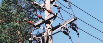
Wire clamp on pole
- Wedge clamp - consists of three metal parts: a base, a wedge and a pressure plate. When the wire is tensioned, it is held in place due to the high friction force. The parts wedge into each other.
In particular, the last version of the clamp can be installed with your own hands. The option shown in the photo above is used for fastening low-voltage wires and optical communication cables.
Soldering iron selection
For high-quality and comfortable soldering of wiring, you need to choose a suitable soldering iron. The selection is made based on power, size, material of the handle and tip.
Commercially available soldering irons are not fully ready for use. Before using them, you will need to carry out preparatory manipulations. The process does not take more than an hour.
Important! When a new soldering iron is first plugged into a power outlet, it starts to smoke. Don't worry
This is absolutely normal. The smoke is formed due to the burnout of the technical lubricant that was used in the production of the soldering iron. It will go away in 3-5 minutes.
Heater power
The power of the soldering iron is selected based on the cross-section of the wires being soldered. The larger it is, the more powerful the device is needed. Thin wires with a cross section of up to 2.5 square meters. mm are successfully soldered with a 25 W soldering iron. For thicker cores, 2.5-10 sq. mm, you will need a 40-60 W device. The thickest wires are soldered with appropriate soldering irons with hundreds of watts.
Soldering irons differ by type of heater:
- from nichrome wire (the most common);
- with induction heating;
- soldering irons, where the tip is heated by current passing through it.
Induction soldering station
There are also differences from an ergonomic point of view:
- classic with an oblong handle;
- soldering iron in the shape of a gun (similar to a hot glue gun)
Important! There are other, exotic types of soldering irons. For example, infrared
Heating is carried out using IR thermal radiation.
Soldering iron tip care
Modern fireproof tips do not require sharpening or maintenance. However, ordinary copper ones have to be sharpened.
During operation, the copper tip heats up to temperatures from 80 to 450°C. Heating causes it to burn out. Pits, craters and depressions form at the tip of the sting. Irregularities interfere with high-quality soldering. Therefore, the shape of the tip needs to be periodically corrected with a file. This operation is needed no more than once a month. According to safety rules, before sharpening the tip, the soldering iron must be disconnected from the network.
Frequent filing reduces the length of the sting. Over time, it will have to be replaced with a new one. Therefore, the tip must be replaceable and removed from the soldering iron (if the tool model allows it). During operation, flux vapors enter the cavity of the soldering iron. They harden and block the sting. Therefore, once a year it is recommended to remove it from the soldering machine and shake out the fumes from the flux from the power tool. If this is not done, then after a few years the sting will become so stuck that it will become impossible to remove it.
Soldering temperature selection
Soldering iron with power regulator
The temperature of the soldering iron plays a key role. A tip that is too cold is not able to melt the solder to the required fluidity. It will not spread properly over the parts being soldered. An overheated tip is also bad. The flux will burn and evaporate from the soldering area too quickly. A characteristic sign of an overheated soldering iron is excessive smoking of rosin. A hot tip is also bad because it becomes covered with a layer of oxide, after which it will not be possible to solder the wire.
Tips from experienced installers
There are many controversial issues both in connection methods and in the use of individual mounting products. But a number of rules apply to absolutely all craftsmen who do electrical installations.
For example, it is strictly prohibited to twist aluminum conductors with copper ones . The process of rapid oxidation leads to the destruction of the commutation and the creation of a dangerous point, which can spark or flare up at any time.
When using electrical tape, overlap the wraps. One layer is not enough, it is better to go along the connection 2-3 times, making sure to make the last turn on the insulation
Single conductors in screw terminals are held loosely. Therefore, it is recommended to bend the stripped end in half or make an arbitrary loop out of it.
At the end of the work, be sure to check the reliability of the connections - lightly tug the wires. It happens that the switching is unsuccessful, and the core simply slips out of the terminal block.
If the volume of the distribution box allows, for example, the panels accommodate a lot of wires and devices, then leave the cable with a reserve. Sometimes switching is required and the extra length is useful if the connections are permanent or burnt.
How to solder with tin without a soldering iron in emergencies
You can solder with tin without a soldering iron using a regular metal clip or a piece of copper wire. You will also need pliers and some kind of heat source. This could be a lighter or a gas burner. Basically, something that could be used to heat a paperclip to a certain temperature.
So, to solder with tin without a soldering iron, you will need to bend the paper clip and clamp it with pliers. Then you will need to heat the paperclip, after which you can begin soldering with tin. The method, of course, is emergency, but it can help out in certain situations. You can also use something else as a paper clip, for example, a piece of copper wire.
Modern technologies
In many cases, the methods discussed are gradually becoming a thing of the past. They were replaced by factory wire connectors, which made installation and switching work much easier and faster:
- Terminal blocks, inside of which there are tubular brass sleeves. Stripped wire strands are inserted into these tubes and secured by tightening the screws.
- PPE caps, inside of which there are compression springs. The cores are inserted into the cap and then turned clockwise with little effort, thereby reliably compressing the connected wires inside.
- Self-clamping terminals. It is enough to place the wiring in them, and there it is automatically fixed due to the pressure plate.
- Lever-type terminal blocks. This connecting element is reusable. It is enough just to lift the lever, insert the conductor into the contact hole and lower the lever back, reliable fixation is ensured.
Welding pencil
This is an affordable tool that is sold in almost all specialized stores. It helps to make high-quality soldering without using a traditional soldering iron. The pencil can be stored in the house for an unlimited time; it is suitable for soldering various metals.
Instructions for using the pencil are included in the package. It's extremely easy to use:
- one end of the pencil must be heated in any convenient way;
- hold the molten end on the desired area;
- wait until the molten material cools down.
The result is a solder joint that can withstand temperatures up to 180 degrees. On average, one pencil is enough to carry out 30 rations.