When choosing switches for lighting residential premises, we are always faced with a dilemma: should we buy a regular light switch, or one with backlighting? Any manufacturer, including the popular legrand, offers the same models, both with and without an indicator.
What is an illuminated switch for? This may sound strange, but for the cleanliness of the walls. Every time we feel the keys in the dark, we gradually grease the walls around us and create scuffs on the covering. The price difference is small, but connecting an illuminated switch obviously provides certain advantages. Why do many buyers prefer traditional models?
The fact is that there are common “horror stories” and myths about the negative aspects of backlighting
What types of switches are there with on indication?
Illuminated Triple Switch
Illumination in electrical switches is a neon bulb or LED. Visually it is almost impossible to distinguish them; the only difference is that neon lamps consume less electricity, but create a larger voltage drop. The minimum current for LEDs to glow is 2 mA, the voltage drop is 2 V, and for neon varieties these figures are 0.1 mA and 70 V, respectively. This is important to consider when choosing an electrical switch.
Switches with an indicator may not work correctly with different types of lamps. The design works smoothly and efficiently with halogen and incandescent lamps. It is better to refuse to use LED and energy-saving ones or take special measures. The most common malfunctions are the light blinking in the off position of the switch, the indicator in the switch does not light up.
The backlight can be equipped on all types of switches and with any number of keys. The location of the glowing indicator can be different: at the top or in the middle of the key, in the center or at the bottom of the device body itself.
How does a backlit switch work?
The main difference between a backlit device and classic models is the presence of an indicator. This could be a neon light or LED.
The connection diagram is simple. The indicator runs parallel to the device terminals. When the devices are turned off, this small part is connected to the zero wire (using the lamp resistance) and begins to glow. When the light is turned on, the circuit is short-circuited and the indicator turns off.
A backlit/indicator switch will not work with the following types of devices:
- fluorescent lamps;
- lighting devices with electronic starting controllers;
- some types of LED lamps.
By functionality, devices are distinguished as one-, two-, three- and four-key, corded and push-button, etc.
Illuminated switches have many advantages:
- The design and construction are almost no different from standard devices. The only difference is the presence of an LED on the front panel, which makes being in a dark room more comfortable.
- Most schemes are economical. Built-in indicators consume very little power.
- Maintenance of the LED does not require large energy consumption.
Often backlit devices are installed in bedrooms. Working backlight helps you quickly find your way around the room if you suddenly wake up.
Important! The disadvantages include the consumption of a large amount of electricity when connected using separate circuits (using a resistor).
Changeover switches - lighting control circuit from 3 places
But what if you want to control one lighting from three or more points.
That is, there will be 3, 4, etc. switches in the circuit. It would seem that you need to take another pass-through switch and that’s it. Here a changeover switch, or as it is also called a cross, cross, or intermediate switch, will come to your aid. Its key difference is that it has four outlets - two at the bottom and two at the top.
And it is installed precisely in the gap between two passageways. Find in the junction box two secondary (not main) wires from the first and second pass-through switch.
You disconnect them and connect a changeover between them. Connect the wires that come from the first to the input (follow the arrows), and those that go to the second to the output terminals.
Always check the diagram on the switches! It often happens that their entrance and exit are on the same side (top and bottom). For example, the connection diagram for a Legrand Valena changeover switch:
Naturally, there is no need to stuff the changeover itself into the junction box. It is enough to lead the ends of a 4-core cable from it there. Meanwhile, you place the switch itself in any convenient place - near the bed, in the middle of a long corridor, etc. You can turn the light on and off from anywhere.
The most important advantage of this circuit is that it can be changed indefinitely and add as many changeover switches as you like. That is, there will always be two passing ones (at the beginning and the end), and in the interval between them there will be 4, 5 or at least 10 crossover ones.
Application of LED Switch
A backlit switch is installed where it is dark even during the daytime, and constant use of the lighting device is impractical. It is also used in rooms where access is required at night.
A switch with LED backlight, just like a regular one, can be solid-body or consist of one, two or more keys
The more light sources, the more keys on the switch will be required. To control lighting consisting of more than three lighting fixtures, dial switches are used, which are installed in one row. To control lighting from several places, purchase a special backlit switch.
Options for using backlights
As an example, let's look at options for using backlights in Legrand products.
The backlight mode in the illustration is indicated by a picture of the month, the installation of a switch with an operation indication is indicated by a picture of a light bulb.
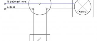
A single-key switch with night illumination is connected according to the classical scheme: a light bulb on contacts L. To indicate operation, a working zero must be set to the backlight lamp.
Connecting a two-key switch is done in the same way. Each operating line has a separate indicator light. The circuit provides separate indication of the double switch, each backlight works for its own line.
The three-key switch works exactly the same way. There will only be three indicators. By the way, this is another argument for opponents of the backlight: a three-key switch in display mode spends 3 times more energy than a double switch.
The pass-through switch can also work with backlight. Only the switching diagram will be different. The indicator is connected to those contacts that will be open when the key is in the “down” position. As a result, if you turn on the light with one of the “pass-throughs”, the backlight on it goes out.
When using the backlight as an indication of lamp operation, the indicator is connected to the lamp side, and a separate working zero is connected to it. Regardless of the position of the “feeders”, when the lighting is turned on, the indicator will light up.
Legrand sells backlight lamps separately. In essence, it is an ordinary LED with a quenching resistor and a freewheeling diode, packaged in a heat-shrinkable tube.
If you don’t want to overpay for the logo on the price tag, you can make a spare indicator yourself. The circuit is simple: in order to prevent reverse current from flowing through the LED element (we have alternating voltage in the network, the polarity changes with a frequency of 50 Hz), a reverse diode (type D226) is installed. And since the voltage drop across the LED is 2–3 volts (depending on the color), a current-limiting resistor is installed in the circuit. Diagram and part values in the illustration:
Any switch can be equipped with such an indicator, the main thing is that the light breaks through the plastic.
We’ve figured out how to install a backlit switch, now we’ll deal with stray light. Cunning craftsmen are already offering for sale certain modules that are connected in parallel with housekeepers and LED lamps.
In fact, these are ordinary load resistors. They actually block unwanted light while using as much energy as a low-wattage incandescent lamp. That is, your lights are turned off, but the meter continues to wind.
To “make friends” between a backlit switch and LED (economical) lamps, you need a pass-through switch.
You connect a working lamp to one output, and an indicator with a separate working zero to the second. In this case, the phase works only for one consumer: either the main lamp or the indicator. In principle, there can be no parasitic glow.
Yes, the connection circuit is more complicated (you will have to draw the neutral wire). But you have to pay for the comfort of use. Electricity consumption is minimal, power no more than 1 watt.
How to connect the power button to the motherboard
Well, the components are assembled, all that remains is to fit one to the other and... hello, new computer! While there are usually no difficulties connecting a processor, memory, or video card, the small wires connecting the contacts of the motherboard with elements on the system unit case force you to scratch your head for a long time: which one leads where?
The pins for buttons, lights, system speaker, and audio jacks look the same, but each motherboard manufacturer places them differently on their products. Today we will talk about how to properly connect the computer's power button to the motherboard and not burn anything.
Front Panel
The area where the power and reset buttons are located, as well as indicators for power, disk activity, sleep and some others on the system unit is called the front panel . On the motherboard it corresponds to the f_ panel .
F_panel may look like in the photo, where each contact is painted a certain color, or it may be monochromatic. The number and arrangement of pins on it are also not the same, so the front panel connection diagram for motherboards, for example, Asus, will not fit Gigabyte motherboards and vice versa.
On some motherboard models, the front panel contacts are labeled, which greatly simplifies the process of assembling the system unit.
But most often they are simply marked with serial numbers, as in the first photo. In this case, you cannot do without instructions.
Power button
There are 2 wires coming from the power button on the front panel of the system unit, which end in a rectangular connector with two holes and the inscription “ POWER SW” (Power switch). Do not confuse it with the “ POWER LED ” connector, the latter is designed to connect a computer’s power indicator.
The “POWER SW” connector is connected to a pair of contacts on f_panel, which are labeled in the same way on the connection diagram. In some diagrams, the Power switch is designated as PSW, PWR , PWR BTN , PWRSW or ON/ OFF .
The front panel contacts have polarity, that is, one of the pair of conductors is connected to the “+” terminal, and the second to the “-”. The Power switch connector also has a minus and a plus, but it can be connected to the motherboard on either side, since it works to close/open the circuit.
What will happen to the computer if you mistakenly connect the power button to another connector, for example, indicators or system speaker? It’s okay - it just won’t start, since the switching circuit, which is closed by pressing the button, will remain open.
In the same way, you should not be afraid of problems if you make a mistake with connecting other elements of the front panel. An incorrectly connected element simply will not work.
Asus
- On Asus boards with a 10-pin front panel connector, the PWR BTN pins are located in the middle (pins 5 and 6).
- On boards with a 20-pin connector they are located on pins 11 and 13.
AsRock
Different models of AsRock motherboards have different locations of Power switch contacts. For example:
- On a 10-pin connector: pin 5 and 6 or pin 6 and 8.
- On a 20-pin connector: pins 6 and 8.
Gigabyte
Gigabyte's front panel connectors most often have 20 pins. The Power switch has pins 6 and 8.
Biostar
Biostar motherboards are not very common in our country, but models with the following PWRSW pin locations are more common:
- On 16- and 24-pin connectors - 14 and 16 pin or 15 and 16 pin, if the contacts are counted in horizontal rows.
- On a 10-pin connector there are 6 and 8 pins.
MSI
On MSI boards, the f_panel connector has 10 pins, the Power switch pins are designated by serial numbers 6 and 8.
Fujitsu Siemens
On the 30-pin Fujitsu Siemens front panel, the Power On/Of pins occupy the 25th and 26th places. Please note that contacts on this board are counted from right to left.
Foxconn
- On the 20-pin contact group of Foxconn motherboards, the Power switch has pins 6 and 8.
- On the 10-pin group there are also 6 and 8.
Epox
On Epox brand products with a 20-pin front panel connector, the Power button is connected via pins 11 and 13.
Intel
Another exotic brand of motherboards, Intel, is available with 10- and 12-pin f_panel groups. The power button is connected to pins 6 and 8.
Lenovo
- On Lenovo motherboard models with a 14-pin front panel connector, the power button is connected to pins 9 and 11.
- On models with 10 contacts, pins 6 and 8 are allocated for the Power switch.
Here are collected only the most common options for connecting the Power button to desktop computer motherboards. If none of them suits you, feed the search engine the request: “model_of_your_board front panel connection” and look at the pictures found. Most likely, the answer will be found very quickly.
Source: https://f1comp.ru/zhelezo/kak-podklyuchit-knopku-vklyucheniya-k-materinskoj-plate/
Types depending on the type of backlight
The parameter for dividing into types, in addition to functionality, will also be the type of backlight:
- With resistor. This circuit for connecting a backlit switch has a drawback - it will not work if the lighting fixtures have LED lamps. It's easy to explain. When operating such devices, it will not be possible to create a high voltage, because LEDs have greater resistance than incandescent lamps. You can connect an energy-saving light bulb here, but it blinks after turning off.
- LED with capacitor. The circuit allows you to increase efficiency and reduce the level of electrical energy consumed by the backlight. The resistor here acts as a current limiter for the capacitor.
- With neon lamp. Switches of this type have almost no disadvantages. Able to work with any lighting devices, including conventional lamps, fluorescent and LED.
All of the above types of devices are used in everyday life.
Features of installation of combined models
The connection diagram for a switch combined in a common housing with a socket is somewhat different from that described above. And the main difference is the presence of an additional neutral wire, laid from the distribution box directly to the outlet. In this case, the output from the switch will have two double wires.
When connecting multi-core wires, in order to prevent them from breaking off under the pressure of the screw clamp, the exposed sections of the wires are equipped with NShVI lugs
To safely connect a switch to a socket, it is better to use a wire with a cross-section of 2.5 sq. mm. And directly to the lighting fixtures from the switch, lay a 1.5 square cable.
At the final stage of installation, all that remains is to check the correct connection of the wires and install the decorative frame. To check the correct connection, you need to turn on the switch and apply voltage.
When you turn on the first key of the device, one lamp should light up, and when you turn on the second, the next chandelier horn or connected electrical appliance should light up.
The frame is fixed using a clamping insert. You need to press lightly on it and snap it on the sides with a little force.
How to choose an LED switch
When buying an LED switch, there is no need to chase expensive ceramic devices, since the power consumption of lighting devices is generally not very large. For domestic use, it will be sufficient to use a high-quality plastic LED switch with a reliable contact group. The service life of such devices is about 40,000 switchings.
For hotel rooms, illuminated switches are used, which are controlled using a key card. They can be with or without a shutdown time delay
The choice is also made based on the design of the device, the type of inclusion - they produce keyboard and rotary, push-button, touch and cord. Depending on the installation method, internal and external devices are distinguished. The case material can also be different - plastic, glass, copper, stainless steel are used, and slate, gold plated and even leather are used as decorative coatings.
But what you really need to pay attention to is the protection class (IP) - it indicates the possibility of using the equipment in certain conditions. For example:
- A class with IP values of 20 or more indicates that the device is poorly protected from dust and moisture. Such equipment is used in residential premises.
- Class IP 45 and higher is used for marking switches suitable for connection in rooms with high humidity - baths, saunas, kitchens, toilets, etc.
- An IP class of 65 means that the switch can be used outdoors. Such electrical equipment has increased protection from dust and moisture. Installed outside the building - under the porch, canopy, on covered verandas. It has more massive keys, and at the point where the electrical wire enters there is a rubber seal.
The higher the class, the more protected the device is from external factors. This applies not only to switches, but also to sockets, toggle switches, and other electrical equipment.
Switch illumination circuit based on LED and resistance
Currently, switches for lighting are usually equipped with LEDs, which are included in the switch according to the electrical diagram below.
When the switch is in the “Off” position, the current passes through resistance R1, then through the LED VD2, which lights up. Diode VD1 protects VD2 from reverse voltage breakdown. R1 of any type with a power of more than 1 W, rated from 100 to 150 kOhm. With the R1 rating indicated on the diagram, the current flows about 3 mA, which is quite enough for a clearly visible glow in the dark. If the LED glow is insufficient, then the resistance value must be reduced. VD1 of any type, VD2 of any type and color of light. In order to understand the theory and independently calculate the size and power of the resistor, you need to read the article “The Law of Current Strength”.
An LED switch illumination circuit can be installed if the lamp uses incandescent light bulbs. If there are compact fluorescent (energy-saving) ones, then it is possible that in the dark you may notice their faint glow or blinking. If LED bulbs are installed in the lamp, then the backlight made according to this scheme may not even work, since the resistance of the LED bulb is very high and a current of sufficient strength for the LED to glow may not be created. In the dark, the LED light may glow faintly. The scheme is very simple, but has a big drawback: it consumes a lot of electricity, about 1 kW×hour per month. This is what the assembled circuit looks like.
All that remains is to connect the ends that point down to the switch terminals. If you did not make any mistakes during installation, the circuit will work immediately. I specifically posted a photo of the twists for those who do not have the opportunity to solder the connections with a soldering iron. For reliability and safety, you still need to solder the twists and cover the bare wires and resistor with electrical tape.
Procedure for installing electrical appliances (step-by-step instructions)
If hidden wiring is chosen, it is necessary to arrange recesses in the walls to install the distribution box and socket box (a plastic box, sockets are also installed in a similar box). If it is open, then you need to mount supports (platforms) on which the devices will be installed. Next, you need to lay the cables in the chosen way, lead them into the electrical outlet and distribution box. After this, you can begin installation. The minimum set of tools that you will need for this:
- wire cutters for shortening wires;
- installer's knife for removing insulation;
- if available, an insulation stripper for stripping wires;
- a set of screwdrivers (at least two).
Perhaps something else will be needed during the process.
First, the wire must be shortened to a length at which, upon completion of installation, it will be possible to close the junction box or install the device in a socket box.
Cable VVGp 3x1.5 with removed outer sheath.
First, you need to remove the top sheath of the cable using a mechanic's knife. This must be done carefully so as not to damage the insulation of the conductors (especially, you must not touch the copper conductors).
Cable with stripped conductors.
Next, you need to remove the insulation from the conductors to a length of 1-1.5 cm. This is also done with a mechanic’s knife, and if you have an insulation stripper, then it is even more convenient for them to work.
Arrangement of conductors before connection.
The cut ends are bent in the desired direction. After this you can start disconnecting. Traditionally, connections in boxes are made by twisting. You can do this now, following two rules:
- Copper and aluminum conductors cannot be twisted;
- all twists must be insulated (with insulating tape or plastic caps).
It is advisable to solder copper strands before insulation.
But in modern conditions, there are more convenient ways to connect conductors in a box. There are various types of terminals available in the market for electrical installation, both screw and clamp type.
Set of clamp type terminals.
Screw type terminal set.
Installation is more accurate, reliable and safe.
Then you can start connecting the switch itself. The first steps are similar:
- shorten the two-core cable;
- remove the outer shell;
- strip the core insulation.
Wires ready to connect the switching device.
Then you need to disassemble the device - carefully, so as not to break it, remove the key and decorative panel.
Disassembly diagram of a single device.
The next step is to insert the stripped ends of the current-carrying wires into the switch and secure them. The order of connection does not matter, but usually the supply end is connected to the bottom terminal, and the outgoing end to the top.
Single-keyboard with connected wires.
Next, the switch is installed back into the box, the petals are opened, and secured to the surface with self-tapping screws.
Fastening the device at the installation site.
After completing the wire connections, you must once again check the correctness of the mounted circuit. Lastly, a decorative frame with a key is installed.
Complete circuit breaker installation diagram.
At this point, the connection of the electric light switch with one key is considered complete. You can apply voltage, then check the lighting operation.
Switch illumination circuit using an LED and a capacitor
To increase the efficiency of the backlight in the switch, you can install an additional capacitor in the electrical circuit, while reducing the value of resistor R1 to 100 Ohms.
This circuit differs from the above by using capacitor C1 as a current-limiting element instead of a resistor. R1 here performs the function of limiting the capacitor charge current. Resistance R1 can be used from 100 to 500 Ohms with a power of 0.25 W. Instead of a simple diode VD1, you can install an LED, the same as VD2. The efficiency of the circuit will not change, and both LEDs will shine at once with the same brightness.
The advantage of a circuit with a capacitor is low energy consumption, about 0.05 kW×hour per month. The disadvantages of the scheme are the same as those presented above and, in addition, large overall dimensions.
Switch illumination circuit for a neon light bulb (neon)
The backlighting circuit for a switch on a neon light bulb (neon) is devoid of the disadvantages inherent in the LED backlighting circuits presented above. This switch illumination scheme is suitable for chandelier switches and any other types of lamps, with both incandescent light bulbs and energy-saving fluorescent and LED lamps installed in them.
When the switch is open, current flows through resistance R1, the discharge lamp HG1 and it lights up. R1 of any type with a power of more than 0.25 W, rated from 0.5 to 1.0 MOhm.
In the photo you see the assembled switch illumination circuit, which couldn’t be simpler. It is enough to connect a resistor in series with a neon light bulb of any type and the circuit is ready.
Where to get a neon light bulb
Neon gas-discharge bulbs (neons) are presented in a wide range and you can use any of them available. Please note that on the left in the photo there is a gas-discharge light bulb with a 200 kOhm resistor, removed from a failed computer extension cord switch, which is also called the Pilot. It can be successfully installed in any switch without the additional hassle of finding components. The same light bulbs with a resistor are installed in electric kettles and other electrical appliances to indicate the on state. In the center of the photograph, a Small-sized Thyratron (triode) with a Cold Cathode MTX-90 unexpectedly appeared. To be fair, I’ll say that the MTX-90 thyratron has been shining in my sconce for decades.
Neon bulbs (neons) surround us almost everywhere. Are you surprised? All older fluorescent light fixtures use a starter, which is a real neon light bulb housed in a cylindrical housing. In order to remove it from the lamp body, you need to turn the cylinder slightly counterclockwise. There are as many starters as there are fluorescent lamps in a luminaire. In the starter, a capacitor is also connected in parallel to the neon lamp; it serves to suppress interference and is not needed in the manufacture of the indicator.
If the starter is taken from an old lamp, before using a neon bulb, do not be lazy to check it. Before installation, you must connect the light bulb according to the above diagram. It is better to take a neon from a new starter, since in old ones the glass of the bulb bulb from the inside is usually covered with a dark coating and the glow will be less visible. A light bulb from a starter can be successfully used to make your own phase indicator.
A ready-made lighting kit for installation in a wall switch can be taken from a faulty modern electric kettle. As a rule, most models have a water heating indicator. The indicator is a neon light bulb with a current-limiting resistor connected in series and this circuit is connected in parallel to the heating element. If you have a faulty electric kettle lying around in your household, then a neon light bulb with a resistor can be removed from it and mounted in the switch.
The photo shows three neon lights from electric kettles. As you can see, they shine quite brightly, so in the dark they will be visible in the switch from a great distance.
If you look closely at the insulating tubes placed at the junction of the terminals of the neon light bulb with the wires, you will notice a thickening on one of the tubes. A current-limiting resistor is located at this location. If you cut the tube lengthwise, a picture will open, as in this photo.
Product Installation
Previously, we looked at the rules for connecting wires from the junction box; now we need to secure the housing to the wall. In this article we consider the installation of a hidden enclosure. The socket boxes should already be installed in the grooves and the wires should be wired.
All you need is to fix the cores with special screws and carefully insert the core into the socket box, as shown in the photo below.
Fixing contacts in the housing
There are 2 screws on the sides that open the fixing side tabs. Using a curved screwdriver, tighten the screws one by one, making sure that the housing does not warp during installation.
Placement in a groove
When the core “sits” tightly in the groove, you just need to install the top decorative cover and check the functionality of the product.
Final step
That's all the instructions for connecting a light switch with your own hands! If suddenly any of the points were not clear to you, ask our specialists a question in the “Questions to an Electrician” category. We also recommend that you watch video tutorials that will allow you to see the whole process more clearly!
Similar material:
Illuminated switch device
Illuminated switch device
Connecting a switch equipped with an indicator light is usually not difficult. It is enough to choose a high-quality model or upgrade an already purchased one.
The backlight in the device consists of neon lamps or LEDs connected in series with each other with resistance. This small circuit is connected in parallel with the switch contact. The circuit is always energized, regardless of whether the light is on or off.
If the switch is turned on, the backlight color is closed by a contact that is characterized by lower voltage. There is practically no current flowing through the backlight, therefore it does not light up.
A current-limiting resistor is connected in series with the neon lamp or LED in the switch. It is installed in order to reduce the current to optimal parameters. LEDs and neon lamps require different amounts of current, so the resistors are set to different values.
- For neon bulbs - 0.5-1 MΩ, power dissipation - 0.25 W.
- For LEDs - 100-150 kOhm, minimum power dissipation - 1 W.
Connecting directly through a resistor is not the best option. This is due to the performance of the circuit, as well as the tendency of the resistor to overheat. It is also possible that reverse current will flow through the electrical circuit. This will inevitably lead to breakdown of the LED.
With diode
Backlight circuit with diode and neon lamp
The first step is to solve the problem of reverse current flow. It's easy to fix - you need to install a diode parallel to the LED element.
If you connect the device according to a given circuit, the power dissipation of the resistor will not exceed 1 W, the resistance will fluctuate between 100-150 kOhm.
It is important to choose the right diode, whose technical characteristics will be similar to those of an LED light bulb.
This scheme, despite its ease of implementation and performance, has a drawback - the backlight consumes a considerable amount of electricity, and the resistor heats up.
A backlit switch of this type is compatible and will work correctly with incandescent lamps. If we talk about economical types and LED chandeliers, then the work will be intermittent.
To save energy with a capacitor
Backlight circuit using LED and capacitor
To eliminate the problem of resistor overheating, as well as to reduce the amount of energy consumed, the circuit is additionally equipped with a capacitor. The parameters of the resistor also undergo changes, since its task is to limit the charge of the capacitor.
The resistor value will fluctuate between 100-500 AM, and the capacitor parameters will be 1 mF, 300 V. The resistor values are established experimentally.
The advantage of this scheme is that it consumes virtually no electricity. Monthly consumption is about 50 W. However, placing a capacitor in a very limited space is quite problematic. Also, the circuit does not guarantee uninterrupted operation with energy-saving and LED lamps.
Connection rules
Regardless of the type, installing an illuminated switch is the same. The differences are only in a couple of nuances.
Where to put the wires
Before you begin installing a switch with an indicator, it is important to understand the design. To do this, it is recommended to remove the keys. Most often they are fixed to the body using pins or a latch.
Under the keys you can see terminals for connecting wires. They almost always visually appear as small copper pads with screws.
To connect the wires, their end must be removed from the insulating layer and the wire must be stripped, passed under the screw and contact plate, and secured securely using the first. You should tighten it with force, but the main thing is not to overdo it, the structure is quite fragile. After a while, it is better to check the quality of the connection again and tighten it again, since the copper gives in slightly under the screw.
Connecting a light switch with one backlit key
Diagram for connecting the backlight to the network
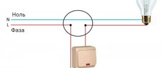
The connection diagram is extremely simple - zero is supplied directly from the panel to the lamp, and a phase is supplied to one of the switch terminals. From the second terminal the wire is fed to the output of the lighting fixture.
Implementing this scheme is simple and quick. The number of terminals depends on the number of keys in the switch. The single design has only 2 terminals, and the socket box must be equipped with two wires. It is simply impossible to get confused. You need to run one wire under the terminal from the panel, and the second from the lighting fixture. Where and what does not matter.
How to connect a switch with two keys and backlight
Connection diagram for a double model with backlight
The connection diagram of this electrical structure is not much different from the previous one. A three-wire wire is brought out into the socket box. Two wires are intended for a group of lighting devices, and one for power supply. This is where all the differences end.
In implementation, the method is a little more complicated, since you need to find a phase conductor and connect it to the required socket. The double switch is equipped with three contacts for connection. The phase is most often displayed in brown or red, and the color of the wires from the lighting device may be the same. Before connecting, the presence of phase voltage is checked, and if necessary, the wire is marked.
Installation of a single switch
Before you begin installation work, you must turn off the power to the room.
Then the old switch is dismantled, if it was previously installed. For this:
- We remove the keys by prying them off with a flat-head screwdriver.
Each key (if there are several of them) is carefully pryed off with a screwdriver and removed from the socket - Carefully remove the decorative frame.
- We unscrew the screws securing the switch to the socket box and pull out the device body from the wall.
After unscrewing the two screws, the switch body can be freely removed from the socket socket
- We loosen the fastenings of the wires and disconnect them.
To disconnect the wires, just loosen the mounting bolts 1–2 turns.
As a result, we will have in our hands the inside of the old switch, which can be disposed of or kept for spare parts.
To properly install a new switch, you need to follow the same diagram as when removing it, only in reverse order, that is:
- Insert the inner part into the socket, having previously connected the wires to it.
- Tighten the bolts securing the socket box.
- Install frame and keys.
- Turn on the switch and check the operation of the device in all modes.
When the light is off, the backlight should be on
It should be noted that the process of connecting an illuminated switch is no different from connecting a conventional device.
Installation and connection of switches with several keys
Switches with several keys are often used in everyday life. With their help, you can control the operation of several lines of lighting devices at once. They are installed in large rooms or, if necessary, turn the lights on and off in several rooms from one place.
The installation of such switches is completely similar to that described above, with the only difference being that one phase wire and several (according to the number of keys) wires from consumers will come from the wall. It is important to connect them in the correct order
How to carry out installation correctly
The illuminated switch mechanism involves a small lamp that glows when the switch is turned off. A small neon lamp or LED along with a resistance element can be used to illuminate the device. The backlight has wires that need to be connected to power during installation.
Preparing for installation and mandatory safety precautions
Without basic knowledge of safety precautions, it is better not to start working with electrical equipment at all. Illiterate electrical installation can lead to electric shock, failure of electrical appliances, and fire.
Basic rules of behavior when working with electricity:
- all work must be carried out in a de-energized network;
- it is unacceptable to overload the power grid;
- check the markings of the wires for compliance with the connected network;
- It is better to replace a damaged section of the network rather than repair it;
- Do not touch connected equipment with wet hands.
A regular indicator screwdriver or multimeter will help determine the nature of the conductors - where is the zero and where is the phase. The indicator is sufficient if the electrical network is single-phase. To analyze a three-phase network, use a multimeter.
Bringing one of the multimeter tentacles to the phase, the other is fixed on any of the conductors. The range for alternating current is set to 220 W. Zero upon contact will show a value of about 220 W, grounding is always lower
Installation example of a 2-gang switch with backlight
The main design differences between LED switches are in the backlight mechanism. It can be ready to use and does not require any action to connect it. Another type of design requires connecting wires that power an LED or neon lamp.
Let's consider a more complex option - how to connect a backlit device, in which the conductors need to be connected independently.
A design feature that allows easy access to the backlight wires can be useful if you need to turn it off
First of all, pry up the keys with a screwdriver or other suitable tool and remove them. Separate the core (internal mechanism) from the body.
Next, determine the correct position of the switch using an indicator. To do this, by touching the contacts with a screwdriver on one side and an indicator on the other, check whether the device is on or off.
If the indicator lights up, it means it is turned on. In this state, turn it so that the keys with the pressed side are located on top.
For a regular indicator screwdriver to work, you need to hold it correctly - the metal part must touch the contact plate, and the top must be touched with your thumb
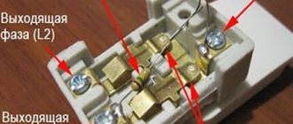
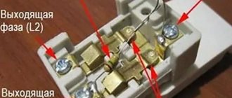
One of the wires coming from the indicator is connected to the input terminal, and the second is connected to the key contact. If there are several keys, then the wire is connected to the first of them, starting from the left. Simultaneously with the wire going from the indicator to the input terminal, the phase conductor is also connected.
The two outlet phase wires that go to the chandelier are connected to the output terminals simultaneously with the second backlight wire, making sure that it does not fall out of contact.
With this connection method, the backlight will turn on after opening the contacts using the first key. The second will not have any effect on turning off the backlight, and the light will remain on even when the lighting is on.
In order for the indicator light to go out when you press any of the keys, you need to make a jumper yourself that will connect the indicator to both keys.
If you do not take into account the connection of the backlight, installation proceeds as in a conventional device. A phase conductor is led through the junction box to the switch and connected to the input terminal L, inserting it into the hole and screwing it in with a screw.
Next, two outlet phase wires are connected to the device contacts L1 and L2, which also lead to the chandelier through the junction box. One of them is connected to one lamp, the other to the other two. The zero passes through the junction box in the wiring box, then goes to all the chandelier lamps, closing the contact.
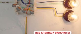
As a result of correct connection, the first key will turn on one lamp, the second two, and two turned on keys will lead to the activation of the entire lighting device. When switched off, the LED (+) should light up.
How to turn off the LED in a switch
All steps to dismantle a neon or LED lamp come down to the technology of replacing a conventional switch. The algorithm of actions is as follows:
- Completely de-energize the apartment or house, check the output voltage.
- Remove the decorative keys using a flat-head screwdriver or prying them with your fingers on both sides.
- The mounting bolts are unscrewed and the structure is removed from the mounting box.
- Using an indicator screwdriver, the contacts of the cores are rechecked for the absence of voltage.
- When the connection diagram has been memorized, the wires are disconnected.
Illuminated switch circuit Redesigned circuit
The disassembled structure of the switch is carefully inspected. It is equipped with latches that connect the two parts of the case. Once they are open, the switch will separate. One part will be equipped with a resistor with an indicator light. The wires of the radio components are carefully cut from the backlight terminal and removed. The switch is assembled and installed in the reverse order.
Instructions: how to install an electrical switch?
Before any installation of electrical equipment with your own hands, you need to do two things
- Determine the live wire using an indicator screwdriver. Mark it with a marker or wrap it with electrical tape.
- Turn off the voltage in the power panel for the entire room where the electrical installation will be carried out. Check the live wire for no load.
Let's look at the installation algorithm
- We snap off the decorative trim from the device, remove the keys or buttons from the lever mechanism. Be careful when removing the panel from its latches. Often plastic elements simply break off.
- Use a knife to remove 3–6 mm of outer insulation from the prepared wires. Lightly clean the ends of the metal from the oxide film.
- We insert one wire into the lower connector of the lever mechanism, and the second into its upper part. We secure them with screws.
- Carefully insert the connected mechanism into the technological hole in the wall. If you are using a pocket for mounting electrics, insert the switch into it.
- We tighten the “whiskers” one by one so that the switch is positioned exactly in the center.
- We check the reliability of the device’s mounting in the wall. It should not dangle or fall out.
- We install the decorative panel and keys.
- We check the functionality.
Advice If you doubt your own abilities, invite a qualified electrician.
Ways to get rid of “blinking” lamps
Everyone loves backlit switches - beautiful, convenient, inexpensive, practical. But they are ideally compatible only with incandescent lamps - conventional or halogen. It’s generally better not to use them with housekeepers - they blink constantly. Can work with high-quality dimmable LEDs. But only high quality ones. Read - dear. And then, over time, if there is a low-quality transformer somewhere, problems may begin. This means that either the lamps will shine at full intensity, or they will “burn out” when turned off. So, connecting an illuminated switch is only possible with “old” lamps?
Convenient - no need to look on the wall
There is a solution to the problem, and even several. Varying degrees of difficulty. Moreover, not all of them work and do not always work. So you can try them one by one. Here's how to make friends with an illuminated switch and LED bulbs:
- Screw one incandescent lamp into a chandelier with LED or housekeepers. The power is selected experimentally.
- If the LEDs are “built-in” and there is no way to add an incandescent lamp without damaging the chandelier, a capacitor with a capacity of 0.22 μF, rated at 630 V, is installed parallel to the chandelier. The same solution is suitable for groups of built-in LED lamps. A capacitor is placed in front of the first lamp in the branch, parallel to it.
- The radical solution to the problem is to “bite out” the backlight circuit. This will not affect the functionality of the switch in any way. The second way is to pull out the neon lamp. This is easier if the circuit is integrated into the body, as is done in Legrand illuminated switches.
Just remove the highlight
- The most correct, and as usual, the most complex solution. Bring the neutral from the panel into the socket box, disconnect one end of the backlight circuit from the terminal, and connect it to the neutral. In this case, the backlight will always be on, but there will be no parasitic circuits that power low-resistance lamps (LEDs and housekeepers).
All options except the last one have one drawback. Due to stray currents that flow through the backlight circuit, LED lamps are constantly energized. As long as the current is insufficient to start glowing, this is simply not noticeable. But the built-in voltage converters are “in operation” all the time. How this affects the lamps is not yet very clear, but there is an assumption that they will burn out faster.
Don't forget about safety
Any manipulations with electrical installations should begin by turning off the circuit breaker, which is located on the communal switchboard. After this, the presence of voltage in the network is checked again with an indicator screwdriver or tester - and so on each time before you start working with the wires.
If the switchboard is located on the landing, then during the work it is recommended to hang a warning sign so that someone does not accidentally turn the toggle switch.
Protective gloves with insulation can also protect against electric shock, although they are not very comfortable when working with wires. When chipping and plastering walls, it is better to wear work clothes, comfortable shoes and a mask or respirator to protect your lungs from dust.
Why do energy-saving lamps blink?
The LED switch is not compatible with energy-saving lamps. A device conflict manifests itself in a short-term flashing of the lamp when it is off or in the so-called smoldering mode, when the lamp does not turn off completely, but barely glows.
The service life of an LED or energy-saving lamp in the wrong mode is significantly reduced and ranges from one to two months
This happens because inside the fluorescent lamp there is an electronic converter (capacitor), which, gradually recharging from the current passing through the backlight lamp, flares up. A similar phenomenon occurs with LED strip power supplies, which also have a capacitor and are powered by a small current coming from the backlit switch.
Manufacturers of energy-saving lamps indicate that the use of their products is not compatible with the use of LED switches and dimmers
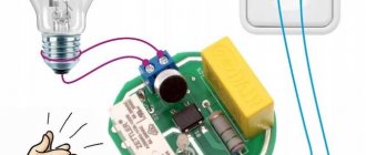
You can get around this limitation by controlling the operation of the lighting device using a relay. From the switch, the command first goes to the relay, which directly controls the lighting. The relay is produced by many manufacturers of electrical goods - Schneider Electric, ABB, Siemens. You can place it under the chandelier cap, behind the cornice in which the LED strip is installed.
You can use another solution to the problem - disconnect the neon lamp or LED from the power supply. This can be done by disconnecting the backlight wires from the terminals. But then the LED switch will lose its advantages. Let's consider solutions that still allow you to combine lighting and the use of energy-saving lamps.
Sources
- https://StrojDvor.ru/elektrosnabzhenie/kak-podklyuchit-vyklyuchatel-s-podsvetkoj-sxema-i-ustrojstvo/
- https://lightika.com/raznoe/kak-podklyuchit-vyklyuchatel-s-podsvetkoy.html
- https://ProFazu.ru/provodka/ustanovochnye/vyklyuchatel-s-podsvetkoj.html
- https://YDoma.info/ehlektrotekhnika/ehlektricheskie-izdeliya/electricity-kak-podklyuchit-vyklyuchatel-s-podsvetkoj.html
- https://220.guru/electroprovodka/rozetki-vyklyuchateli/podklyuchenie-vyklyuchatelya-s-podsvetkoj.html
[collapse]