Author of the article
Yuri Sanaev
System Administrator. Sales manager of computers and wi-fi equipment. Work experience – 10 years. Knows everything and even more about hardware and software.
If a user wants to create a local network at home in order to have shared access to files from all devices, he may have problems crimping a twisted pair cable into 8 cores or 4 cores.
To cope with the task, let’s figure out what types there are, what wires, plugs and tools are needed. We will provide crimping diagrams and tell you which one is suitable in a particular situation.
Cable termination tool
Before doing anything, you need to prepare, or rather prepare the tool. The minimum that is needed is a special crimping tool for terminating and cutting twisted pair cables. It is also called crimping, press tongs or crimper.
Note: I have shown an expensive professional tool as an example. It is heavy, massive and has already compressed about 1000 patch cords, but this is not the limit for it. There are cheaper, lighter and simpler pliers, but they all have the same meaning - to clamp the cable with knives in the RJ45 connector. It’s just that cheap ones are suitable only for one-time operations, but an installer or system administrator needs more reliable flares.
Any crimper has blades for cutting cables and blades for removing braiding from twisted pair cables, so for a person who already has a full hand, one will be enough. But for those who do this occasionally or for the first time in their life, another tool for removing insulation, a stripper, will be of great help.
Sometimes, it may come complete with crimping. If you don’t have one at hand, then a regular stationery or slotted construction knife will do. Just use it very carefully - it cuts your fingers instantly, deeply and very painfully out of habit.
Also, personally, when I terminate a cable, I prefer to cut it with normal wire cutters, rather than with a blade on a crimper. Somehow I immediately got used to it and it’s more convenient for me.
A few words about the LAN cable design
Often a situation arises when it is necessary to make new patch cords or repair a LAN cable. Despite the popularity of Wi-Fi connections, more and more users prefer switching using wires. It is this connection method that allows you to achieve a stable signal supply.
The LAN cable often fails. Most often, such a nuisance occurs against the background of:
- broken latch on the body of the connector;
- wear of the contact group of the connector;
- accidental damage, etc.
Before you start studying information on the topic - how to crimp a wire for the Internet, you should understand the structure of the LAN cable.
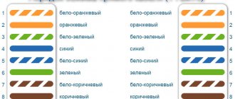
Wire layout color scheme
UTP cable or so-called twisted pair cable consists of four pairs of wires. 10/100BASE-T Ethernet networks use only two pairs of wires (orange and green). The other two color pairs (brown and blue) are used for Gigabit Ethernet networks. Currently, there are two standards for laying out wires by color for crimping from to connector - T568A and T568B.
As a rule, twisted pair crimping can be done in one of two ways:
- Straight. This is a regular patch cord that is now used everywhere. For it, both ends of the cable are crimped according to the T568A standard or the T568B standard. The main thing is that the pinout of the connector at both ends is the same. This patch cord is suitable for connecting a computer to a router or switch, as well as connecting two routers or switches.
- Cross or Cross-Over. This standard was used to connect two computers directly via Ethernet. Now that network adapters are already smart enough and are able to recognize the type of connection themselves, the need for cross-patch cords has practically disappeared, but I will still consider it.
Twisted pair 4 cores
As I said above, for a regular 100-Mbit network connection, only 2 pairs are used - orange and green, that is, only 4 out of 8 cores. Therefore, now on the market there is a cheaper UTP cable for providers, which has only 4 cores. In my experience, it is much worse in quality and works normally on a line length of up to 90 meters. But you also have to work with him quite often. The RJ45 pinout by color is exactly the same here. You just need to “subtract” the remaining 4 wires from the usual layout.
Thus, we find that we are using contacts 1,2,3 and 6. Yes, the sixth track of the connector is sometimes quite difficult to get into and out of habit you will have to suffer. But experience is acquired and after the tenth connector everything goes much easier.
A brief explanation of what twisted pair is
The Internet cable that is used to provide the Internet is called twisted pair. This cable often consists of two or four pairs twisted evenly together. The cores consist of copper or bimetal (copper-plated aluminum), the thickness varies from 0.4 mm to 0.5 mm. Each lived in isolation. All these pairs are contained in a protective plastic outer shell.
The network cable is available for outdoor and indoor use. For outdoor work, the outer sheath is made much stronger so that under the influence of the external environment (rain, snow, wind, sun, temperature changes) the wire will last as long as possible. Twisted pair cables are sorted into coils 305 m long. At bazaars you can buy from one meter.
Types of twisted pair
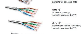
The range of network cables for data transmission (Internet) is small, but still available. Let's look at the most popular and popular among users and providers. Below in the photo we show the twisted pair options.
UTP is the most commonly used cable because it is inexpensive and will last quite a long time indoors.
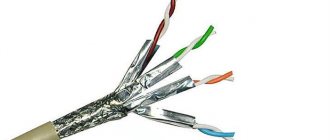
FTP differs from UTP in the presence of a screen made of thin foil.
SFTP - in addition to the screen, a metal braid was added to this wire so that there are no breaks over long spans.
S/STP, STP – cable with double shield, one common, the other shielded each pair. Thanks to this, this wire can be routed over distances of more than 100 meters. It is also used when laying near electrical wires.
SF/UTP – A cable that combines a shield and a metal braid.
There is single-core and multi-core twisted pair.
- The disadvantage of single-core is that it bends poorly, but the data transfer performance is better. It is easier to crimp and the laying distances are longer.
- A multi-core network cable, on the contrary, bends perfectly, but the distance over which it can be stretched is much less. When crimping, problems arise due to fragility; you have to crimp several times. This type of wire is well suited for places where there are a lot of bends in the wiring.
Network wire categories
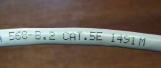
For wired Internet use categories CAT5, CAT5e, CAT6, CAT6a. It is not difficult to determine what category your twisted pair cable has; you can simply look at the outer shell. The protective sheath comes in different colors: gray is the most common, ordinary twisted pair, orange is used in wooden buildings because it is non-flammable.
How many wires are in a twisted pair
Most often you can find a lan cable consisting of two pairs (that's 4 wires), or four pairs (that's 8 wires). The difference between them is in throughput, if a 2 pair wire can pass up to 100 MB, then a 4 pair wire can carry more. Often in a 4-pair wire, 2 pairs are used to power equipment (switch, access point). We definitely recommend taking a 4-pair twisted pair cable at once, even though only 2 pairs are needed to transmit the Internet, do not forget about breaks. If one wire breaks, no problem, you have 4 spare wires.
How to crimp a twisted pair into RJ45 - sequence of actions
We start by using a stripper or knife to remove the UTP cable braid by about 2-3 centimeters. With this length, cable layout by color is much easier. Only the outer braid is removed - no need to strip the cores!
We unravel each pair and arrange the strands by color. I usually smooth them out with my fingers until they more or less keep an even shape. After this, we trim the ends at a distance of approximately 5-7 millimeters from the outer braid and try on the RJ45 connector.
Why am I leaving such a short ending? Look at the photo! This length is just enough for the cores to fall into place, and the outer braid to go almost to the beginning of the tracks in the connector. When crimping, the plastic foot securely clamps the braid and the cable sits very firmly and securely in its place.
It’s easier to crimp UTP onto 4 wires into RJ45 on one side, there are fewer wires:
But with the last vein, out of habit, you will have to suffer. For the photo, I deliberately did not trim the wires so that you could see how they fit into the connector. In practice, they should also be made no more than 70 millimeters long.
As soon as you manage to thread the cable correctly, insert the connector into the socket of the press pliers and squeeze the handles until they stop. Since we often have to deal with the fact that the knives are often not fully compressed, I usually advise releasing the handles after this and squeezing them again. The patch cord is ready and you can check it!
How to crimp an Internet cable with a screwdriver
There is a lot of different trash on the Internet, and one of them can be considered crimping a twisted pair cable into an RJ45 with a screwdriver. Many, many years ago, when I was just studying, I found such instructions on the Internet and, due to my inexperience, believed that this was the normal way.
In fact, this is far from true! Then I broke several connectors and the next day I went for a crimper. Now, having quite a lot of experience, I can crimp the cable with a screwdriver more or less normally, but! The quality of such a patch cord is extremely low. It will still not be possible to bring the connector knife to the end normally. Therefore, I highly do not recommend this method!
Preparing to crimp the Internet cable
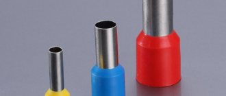
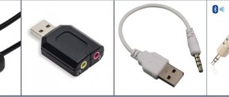
In order to properly crimp an Internet cable at home, you need a minimum of equipment. First, you need the cable itself. If we are talking about an Internet cable, then you already have one. This is the cable that was provided to you by your Internet provider. Secondly, you need RJ-45 connectors (photo below).
These connectors can be purchased at computer stores or ordered online. Typically, such connectors are sold in packs of 100 pieces, but you can also find them individually. If you buy individually, it is better to take it with a reserve, in case something goes wrong.
You will also need a tool for crimping the Internet cable (photo below), also known as a crimper or simply “crimp”. This tool can also be found at small computer hardware stores or online.
If you are not ready to buy a crimper, then you can get by with a simple screwdriver and do it yourself. But, in this case, the process of crimping an Internet cable becomes a little more complicated.
Removing the outer layer of insulation
If you want to crimp an Internet cable, then the first thing you need to do is remove the outer layer of insulation. To do this, you can use a sharp knife or a blade on a cable crimping tool (crimper). Run a blade around the insulation of the Internet cable in a circle and remove about 2-3 centimeters of insulation.
At the same time, try not to damage the internal wiring. If the internal conductors are nevertheless damaged, then this section of the cable must be completely cut off and the process of crimping the Internet cable must begin again.
Preparing internal conductors
Next you need to untwist all the twisted pairs of conductors inside the Internet cable and straighten them slightly. There is no need to torture them particularly, so that fractures do not form inside the conductors. Just unravel and straighten a little.
After you have removed the insulation from the Internet cable and straightened the conductors, you need to arrange them in the correct order. There are four standards that determine the order of conductors in a connector. These are two standards for straight cable (TIA/EIA-568B and TIA/EIA-568A) and two standards for crossover. You can learn more about the circuits that determine the order of conductors here.
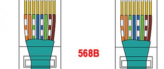
In most cases, to crimp an Internet cable, you need to use a straight TIA/EIA-568B conductor layout (illustration below). If your Internet cable has already been crimped before, then you can simply look at how the conductors were located in the old RJ-45 connector.
Once you have decided on the circuit, align the conductors and arrange them in one line in the desired order (as in the photo below). If the conductors are too long, they need to be shortened. This is conveniently done using a blade on a tool for crimping an Internet cable (crimper).
Now you need to insert these wires into the RJ-45 connector. If they are located in one line, then they will go in easily and each will take its place inside the connector.
Before you begin directly crimping the cable, make sure that all conductors have reached the end of the connector.
Crimp the internet cable using a crimper
Once the cable is inserted into the RJ-45 connector, you can begin crimping. To do this, insert the connector into the crimper and squeeze the handles of this tool quite firmly.
If you don't have a crimper, you can get by with a simple screwdriver. In this case, you need to use a screwdriver to push through each pin on the RJ-45 connector.
At this point, the process of crimping the Internet cable can be considered complete. Connect the cable to your computer and check if there is internet. If there is no Internet, then you did something wrong. Try cutting off the RJ-45 connector and crimping the Internet cable again.
Compression methods
The Internet cable uses twisted pair, which consists of 8 cores (or less - 4). Therefore, it is necessary to use special connection methods (preferably with special equipment), because if the contact is of poor quality, then working with the Internet will become unavailable.
To carry out the operation, it is advisable to use a special crimper for the RJ-45 Internet connector sockets. You can also use special pliers called “crimping”. In emergency situations, experts can use a regular flat-head screwdriver or pliers, but this procedure will be one of the most unreliable (there is a risk of damaging the cable and the plug itself).
Important! The crimping method itself is quite simple: you just need to insert the wire into the socket and use special pliers, pressing them all the way. It is much more difficult to decide on a scheme.
Using pliers, you can not only carry out the above operation, but also clean the insulation, bite off excess cable, or straighten the wires before crimping.
If there is no special device, then, as mentioned above, you can use the “home method” of crimping - using a screwdriver and a knife:
- carefully strip the cable without damaging it;
- insert the wires into the connector according to the required pattern;
- press on each contact in turn, thus securing it.
The home method has a number of disadvantages, for example, the screwdriver will constantly slip off, and there is a possibility of damaging the wire.
You can also use the pliers method to perform the operation. But it is very inconvenient to carry out such an operation, since the plastic housing of the connector can be damaged. It is required to crimp on each side of the cable. If in the middle several leads do not press completely, then it is advisable to return to the method with a screwdriver.
Twisted pair pinout diagrams
There are two main twisted pair wiring diagrams:
- Straight.
- Cross (cross).
Block diagram of the possibility of data transfer between devices with direct and cross connection schemes
Direct crimping of internet cable
Direct scheme - used if you need to connect a PC to a hub (switch) or router (router).
Pinout of an Internet cable for 8 wires in a straight line
Cross-crimp network cable
Cross circuit - used to connect two devices of the same type - computers or routers.
Colored twisted pair pinout diagram for 8 wires - cross arrangement for communication between similar equipment
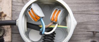
How to repair or change the plug on a network cable
Below you can find tips that will help you replace the plug on the cable or fix it. To do this, the master will need a screwdriver. In order to do the installation, you should use the instructions below.
- The insulation is removed from the cable, and the cores are untwisted.
- At the next stage, the length is measured along the entire body of the plug. The wiring must reach the contacts.
- After this, you will need to install the cable, fixing each of the cores along the contact channels.
- The contacts are embedded in the veins.
After this, the cable is checked for functionality.
Often the plug stops functioning normally. This appears in the background:
- internal cable break;
- poor contact of the plug with the network card slot.
The problem can also arise when the wires do not come into contact with the contacts of the device.
Experts recommend not wasting time and checking with a tester/multimeter. Each transaction will need to be ringed slowly. To do this, one probe is installed on a certain section of the wire, and the other on the second part of the cable. Voltage will be applied to each of the veins in turn. In the event of a break, this will make it easy to find the problem.
How to crimp a twisted pair onto 4 and 8 cores
There are two main wire layout standards - T568A and T568B. In addition, it is possible to transmit an information signal using only four wires instead of eight.
Self-crimp connector eliminates the need for a crimper
Crimping twisted pair 8 cores - color scheme
The order of the wires is regulated by two standards: T568A and T568B
Wiring order according to T568A and T568B standards
What is the difference between the T568A and T568B standards? Let's start with the fact that at the moment the newer T568B standard is almost universally used. It was originally developed to provide feedback to uCoz, a website management system from the uKit Group. However, at the moment, publicly available protocols have become so widespread that the T568B standard is used in PC network settings as a predefined template.
Crimping twisted pair 4 cores - color scheme
UTP (twisted pair) cable consists of four pairs of wires with unique color coding. The local network of the Ethernet 10/100BASE-T standard for transmitting information via Internet communication protocols (TCP/IP v4/v6) used only two of the four pairs - orange and green. The remaining pairs, brown and blue, are used to transmit data from other network applications. For example, in fax-modem connections they are responsible for the telephone.
Pinout diagram for straight and crossover cables with 4 cores
Secrets from installation practice
A few tips for laying out cables for the Internet and crimping twisted pair cables:
- It is most convenient to straighten the veins and place them with a pencil or pen. The wires are smoothed out and placed close to each other, which is what is required for their installation inside the connector.
- The cable insulation must fit into the connector and be clamped. This will avoid possible breakage of the connector.
- After crimping the connector, you need to make sure that the wires are seated tightly in the connector until it stops. This will avoid bad contact.
If possible, it is better to buy a crimper or ask someone for it. It is more convenient to use than a regular knife, and it will not damage the insulation of the cores.
You can do twisted pair crimping yourself if you know the procedure and understand what is required. It is important to do everything efficiently, otherwise a poor-quality connection will cause a poor signal and regular connection interruptions.
Straight and cross crimp
Now let's move on to crimping options. They come in two types:
- Straight, that is, both ends of the twisted pair are crimped according to the same standard.
- Cross, in this case one of the ends is crimped according to the T568A standard, the second - T568B.
Figure 12. Direct (A) and cross (B) connection
This specificity is associated with the connection diagram. There are actually three options:
- Router-router. In this case, a cross line connects two routers or hubs.
- PC-PC. Everything is clear here, a network cable is used to directly connect two personal computers.
- Router-PC. That is, a personal computer is connected to a network node.
Let's take a quick look at the listed connection diagrams.
Crimping twisted pair cables according to the router-to-router scheme
With this connection option, it is necessary to use a direct circuit (see A in Fig. 12). But, when using smart nodes in the network topology, this restriction does not have to be observed. That is, direct and cross connection schemes are allowed, since the router is able to recognize its type. But, it is considered correct to adhere to the selected standard for a particular LAN.
Crimping twisted pair cables according to the computer-to-computer circuit
A completely different situation arises when PCs are connected to each other. In this case, only a crossover circuit can work. This type of connection was demonstrated in Figure 12 (B).
Crimping twisted pair according to the router-computer circuit
This type of connection is usually performed in a direct manner. For smart switches (switches), this condition is not necessary, but nevertheless, it is considered “good form” to adhere to this condition.
Current standards for crimping an eight-core cable
Currently, all specialists involved in laying high-speed communication lines carry out their direct responsibilities, guided by the provisions of the standard called TIA/EIA-568.
- As the norms of this standard state, crimping an eight-core cable can be done using two methods:
- Direct method.
- Cross method or, in other words, cross method.
When a twisted pair is crimped using the direct method, the sequence of wires in the connectors located at the two ends of the patch cord is symmetrical. At the same time, the cross method involves partial crossing of the wires, and the connectors ultimately become asymmetrical.
Standard A
Below you can see a diagram of how a twisted pair consisting of eight cores is crimped in a direct way. As you probably noticed, the diagram shows two typical options for crimping twisted pair cables according to the rules of the TIA/EIA-568 standard.
The option on the left side of the picture is typical for Russia and other CIS countries. The option shown on the right side of the diagram is typically used in the United States and European countries. The only difference between the options is that the locations of the orange and green wires have been replaced.
The main area in which patch cords made using direct crimping of an eight-core cable are used is connecting computers and laptops to various network devices that provide access to local networks or the Internet.
Standard B
Below you can see a diagram of how an eight-core cable is crimped using the crossover method. When using a method called Crossover, the connector on the other side of the cord simply swaps the green and orange wires. Twisted pairs for Ethernet networks are crimped in this way.
If you use the Gigabit Crossover circuit for crimping, you will need to cross all eight wires together. Cables with similar crimping are used for networks with high data transmission speeds, for example, 1000 Base-T.
How to check the quality of an Internet cable crimp
After the cable has been crimped, you need to make sure that the connection is working. To do this, one of the following methods is usually used.
The first method is a cable tester
Professional workers use special devices - LAN testers. Typically this device consists of two parts. This makes it possible to simultaneously test both ends of the network cable at the same time. The main and additional devices have ports for connecting connectors. After connection, the used wires are tested.
The device has indicators corresponding to each of the wires being tested. They will display the results obtained during the test. If any contact is crimped poorly, this will be easily detected.
The second option is a multimeter
The main way to monitor your home is to use a multimeter. When testing, it is set to ring or use the smallest resistance (for example, 200 Ohms). In this case, it is advisable to turn on the sound indication. To check, take both Internet plugs of the network cable and place them next to each other. Then each pair of wires of the same color is called. If there is no electrical contact between them, this will be immediately detected.
This check does not require much time. An important condition is to use sufficiently thin probes. To obtain them, it is necessary either to use thin wire, or to sharpen the commonly used probes.
If at least one pair of wires does not ring, you will have to crimp the network cable again.
Important! Sometimes it happens that the connectors of one cable are not located in the same room at the same time. In this case, there is also the possibility of checking.
The fact is that there is an electrical connection between wires of the same color. In this case, consider a colored wire and a striped wire of the same color. Thus, one wire can be inserted into the socket intended for it, and in the second, measure the resistance between each of the indicated pairs. Its value should be approximately equal in all cases. If this is not the case, then this means that the cable crimping was of poor quality.
The third method is to connect the device with other devices
This option is the easiest way to check. In this case, you need to connect your computer and check if there is a connection to the Internet or local network. If everything works fine, this means that the cable was crimped correctly.
Crimping procedure
Now let's move on to the correct way to crimp the cable. Be careful when working - the main thing is not to damage yourself, and the connectors are cheap).
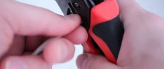
Step 1. Remove the insulation
First, remove the insulation from the wire - you can carefully pry it off with scissors or use a stripper on a crimper - insert it, turn it, and the wrapper comes off. It is fragile and can be removed quite easily. You don't need to remove much insulation - a couple of centimeters from the end is enough. If anything happens, you can trim everything later. The pliers have special marks indicating at what level the coating should be cut.
Step 2. Straighten the wires
Now we take our wires, straighten them and arrange them according to the pinout diagram. From the recommendations - try straightening them with a pencil or hand - they become smooth and closely spaced to each other - which is what we need.
Step 3. Trim
Now is the time to cut and straighten our wires. We cut it either with wire cutters, or with the same pliers, or even with a knife. Leave about a centimeter of clean wire. With practice, you will learn to accurately check the distance.
Step 4. Getting into the connector
The hardest part. Now we need to insert our design into the connector. When inserted, the connector is positioned with the leg down. Why is it difficult - the wires try not to fall into their grooves, they crawl into neighbors, bend, and get tangled. Here the recommendation - patience and once again paying attention to the pencil treatment - helps.
Step 5. Insert all the way
After the hit, we press on the cable so that the wires go all the way. In this case, the wrapper will be hidden in the connector itself. If the wrapper does not fit into the connector, fractures are possible in the future. If the opposite turns out to be short, the wires will not reach the knives. So everything is done with experience and by eye.
Step 6. Crimping
Now is the time to tighten our knives - the methods were discussed above, but it is better to use pliers. Take it and live it.
Step 7. Check and refinement
Be sure to check the connection on your computer or router before putting away your tools. Sometimes it may not work out the first time. The easiest way to correct the situation before getting upset is to squeeze the knives again, but harder. It helps a lot.
If there is no connection, pay attention to this:
- Are the wires routed exactly according to the diagram? Didn't they fly out? Look through the connector.
- Have the wires reached the stop of the connector? Were the knives able to reach them?
The rest can only be attributed to cable failure.
Initially, before crimping the network cable, you can install these casings. They perfectly protect against bending near the connector, but in practice everything works without them. There are a lot of species, that’s not what the article is about. For reference.
Crimping diagrams and twisted pair markings
When crimping a twisted pair of 8 cores, be sure to take into account the markings of the conductors. Each connection necessarily corresponds to a specific color scheme, which requires strict adherence. Otherwise, the signal will not pass through, and the network will not function.
Lazy crimp 2 pairs
In the considered option, direct crimping of the cord is used, where not 8, but only 4 cores are involved. Therefore, this method got its name for those who do not want to bother with all the veins. However, such a connection is only suitable for low-speed networks.
This type of crimping is not recommended for use at this time. The fact is that Internet speed is constantly growing, equipment is improving, and the 4-wire circuit stops working under new conditions. Therefore, sooner or later, you will have to switch to the standard scheme. If the network was initially laid with an 8-core cable, then all that remains is to crimp the RJ connectors in a new way, and everything will work. But, if the network is equipped with a four-core cord, then it will have to be completely changed and re-laid.
Pinout for a local network with more than 2 computers
When using RJ 45 connectors, pinout for connecting more than two computers to a network is carried out according to the standard scheme. All veins are untwisted and laid from top to bottom or from left to right as shown in the figure.
The conductors are aligned, cut, and then they can be crimped. After this, each twisted pair connector is connected to its own socket.
Direct pinout is marked as 568B
Direct connection is necessary in order to connect a HUB, router or switch to a computer. This method is most widespread in Russia. It is marked as 568V, and the wiring is carried out according to the usual scheme, starting with a white-orange conductor and ending with a brown one. There is a direct crimp here, since the wires are located the same on both connectors.
Crossover pinout is marked as 568A
Another way to crimp a twisted pair cable. To connect devices of the same type, for example, two computers, a crossover circuit or crossover labeled 568A is used. In this case, the first plug is connected in the usual way, and the second is connected by replacing the orange and white-orange wires with green and white-green wires. The conductors end up upside down, which is why the circuit got its name.
Direct crimp with 4 core twisted pair double pair wire
A cable with four cores is used when installing internal networks with low speeds. With large volumes, you can save significant money, since such a cable is much cheaper than a conventional twisted pair cable with 8 cores. Crimping is performed in the sequence shown in the figure.
However, the use of such networks has a number of limitations, primarily in terms of speed. In addition, it is not possible to supply power to the device when needed.
RJ 45 twisted pair compression circuit with POE standard IEEE 802 3AF
This circuit, made using PoE technology, allows not only to transmit information signals, but also to supply power to the router, switch, adapter and other devices. For example, when connecting video cameras, a separate power cable is not required. Thus, the connector combines two functions at once - data transmission and power supply to the device. The voltage in this pinout is supplied through blue and brown conductors.
It is strictly forbidden to use twisted pair to supply 220 volts, as this can lead to unpredictable consequences. The fact is that the cross-section of the cable in the network is only 0.51 mm2 and is designed for a current of up to 1.5 A. If the current needs to be increased, two conductors are connected in parallel and then the figure increases to 3A.
Cross-circuit for pumping speed of 1 Gbit/s
The connection scheme is used in high-speed networks, up to 1 Gbit/s. Eight wires are crimped in the sequence shown in the figure.
Rollover Cable console cable crimping diagram
Each end in such a connection is crimped mirrored in relation to each other. This scheme is used to configure a switch or router using a computer.
Standard crimping patterns
There are two rj 45 twisted pair crimping or pinout schemes:
- straight;
- cross.
With direct crimping rj 45, the connectors (plugs) on both sides of the wire are connected according to the same circuit, but with cross crimping, the circuit changes.
Important! The speed of information transfer depends on the crossover connection option.
On the connector, the sockets for the wires are numbered and each of them is intended for a wire with a specific color, in accordance with the selected option. Option T568A has the following connection diagram:
- 1. white-green;
- 2. green;
- 3. white-orange;
- 4. blue;
- 5. white and blue;
- 6. orange;
- 7. white-brown;
- 8. brown.
Option T568B is connected according to this diagram:
- 1. white-orange;
- 2. orange;
- 3. white-green;
- 4. blue;
- 5. white and blue;
- 6. green;
- 7. white-brown;
- 8. brown.
For direct connection, the last option is mainly used; for mixed connection, both are used.
Option No. 1 - straight 8-conductor cable
This option is suitable for connecting different types of electronic devices. For example, a cable connected using this option is used to connect a computer to switches. The rj 45 plug is crimped according to version T568B on both sides of the cable.
Option No. 2 – 8-wire crossover
To connect devices of the same type, such as a computer-to-computer, a crossover is used. Crossover or cross circuit is carried out in two ways:
- data transfer speed is 100 Mbit;
- speed reaches 1000 Mbit. In the first case, the rj 45 connector is crimped at one end of the cable using option T568B, and at the other end using option T568A.
In the second case, the plug is crimped according to option T568B, and the other end in this way:
- white-green;
- green;
- white-orange;
- white-brown;
- brown;
- orange;
- blue;
- white and blue.
Advice! To connect a twisted pair cable with a shield, use a connector with a metal casing.
Option No. 3 - straight 4-wire cable
For low-speed networks, 8-pin (8-socket) plugs with four wires can be used. To do this, it is important to know which contacts should be involved. 1 and 2, 3 and 6 slots are used. Any two pairs can be taken, but it is important that the connection is the same on both ends, for example:
- white-orange is connected to 1 contact;
- k 2 – orange;
- to 3 – white-green;
- by 6 – green.
Warning! The remaining two pairs of cable cannot be used for other connections, since the contact between the cores will be broken, which will cause interference. A direct connection may be required for older electronic devices or a low-speed home network.
Option #4 – 4-wire crossover
This option is more for informational purposes, since it is not advisable to deliberately reduce the speed for modern devices. Let's look at how you can make a pinout for rg 45 - one of the names is rj 45. To get a crossover cable, just swap the connected pairs. Let's say the first connector is connected according to the diagram shown above, then the second is crimped as follows:
- 1 contact – white-green;
- Contact 2 – green;
- 3 contact – white-orange;
- Pin 6 – orange.
The purpose of direct and cross connection is the same as when using 4 pairs.
Application area
Press pliers have a wide range of applications in the field of radio, - and electrical engineering. Use a crimper for crimping:
- thin-walled tips of stranded wires;
- thick-walled stranded wire connectors;
- large cross-section cable sleeves;
- sleeves for serial connection of wires;
- RJ-45 connectors for computer cables.
Crimping of thin-walled stranded wire lugs
Thin-walled connectors are divided into three types:
- NSHVI;
- Sheath;
- Ring.
NSHVI
Pin lugs are necessary for reliable fixation of wires in sockets of radio equipment. The lugs are made of thin metal to tightly grip small cross-section multi-core cables ranging from 0.5 to 3.5 mm2. The fittings are designated by the marking NSHVI.
Important! Crimpers with markings for opening sizes of 0.5-3.5 mm2 reliably and firmly crimp NShVI tips, which are often used in assembling various radio devices. NSHVI
NSHVI
Sheath
Thin-walled terminals for stranded wires include sheath connectors. They are used for serial connection of wires in devices with high temperature conditions where soldering may lose its properties. These are irons, electric kettles, microwave ovens and various heating devices.
To crimp sheath-type terminals, crimpers with special dies are used. The terminal has two pairs of brackets. One of them clamps the bare bundle of wires, the second brackets cover a section of the insulated conductor. The terminals are distinguished into “father” and “mother”. The connection occurs by inserting the plate of one tip into the tubular clamps of the second terminal.
Scabbard terminals
Ring
The terminal has a ring configuration for screw fastening. For crimping them, crimpers with dies for wire cross-sections from 0.25 to 16.8 mm2 are used. Ring shanks are used for fastening wires in various power distribution boxes and panels.
Ring thin-walled tips
Crimping thick-walled stranded wire connectors
Massive lugs are used for crimping multi-core wires and cables with a maximum cross-section of 16 mm2. Crimping pliers type PK-16U are designed for such work. The crimper develops a powerful force on the die jaws. Therefore, press pliers are used only for multi-core wires. The tool can easily bite through a single core.
Pliers PK-16U
Note! The letter “U” in the marking of a crimping tool means that the tool is equipped with a reinforced ratchet mechanism
Crimping of large cross-section cable sleeves
For crimping large-section cable sleeves, a manual hydraulic press is used. These are press pliers that develop powerful force thanks to the built-in hydraulic mechanism.
Hydraulic Press
A reinforced crimper is especially needed when laying and switching power cables in power switchboards, both at industrial facilities and in buildings for various purposes.
Consistent crimping of wire sleeves
The serial connection of wires is made by increasing the length of the electrical circuit. This is especially in demand when connecting cores of different metals. When connecting an aluminum core and a copper wire, a through crimp sleeve is used. The sleeve ensures non-close contact of unlike metals, which eliminates the destructive interaction of atomic lattices of different conductors.
Crimping is carried out in the following order:
- the wires are freed from insulation at a distance equal to half the length of the sleeve;
- the cores are inserted into the sleeve on both sides;
- Crimping is done with a crimper on both sides of the sleeve.
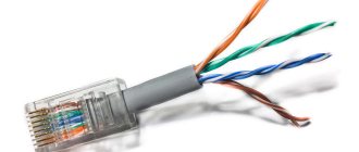
Crimping RJ-45 connectors of computer cables
Polymer RJ-45 connectors provide quick connection of cables to computers or connection of additional equipment to them. The cable in this case is a twisted pair, where the insulated cores are intertwined with each other.
Network cable crimping pliers
For twisted pair cables, crimpers with special matrices are used. Crimping is carried out in several stages:
- the wire is cleared from the outer sheath to a length equal to the depth of the plastic connector;
- twisted pair is divided into individual wires and grouped by color in a certain position (see below for additional information);
- the wiring is inserted into a special opening of the pliers and the ends of the wires are stripped of insulation;
- the plastic connector is covered with a crimper;
- a group of cores is inserted into the RJ-45 housing until it stops;
- squeezing the plastic with pliers and pressing the wires into the connector.
Polymer RJ-45 lug
The wires of the network cable are grouped from left to right before entering the connector:
- white-orange;
- orange;
- green-white;
- blue;
- blue-white;
- green;
- white-brown;
- brown.
Mistakes made during compression
To understand where the error was made, you need to check where its source is. To do this, you need to try using a different network cable and make sure that the connected device is in good condition. If after checking it turns out that the cable does not work, then the following errors should have occurred during crimping:
- The wiring layout is confusing.
- They are lightly pressed against the connector contacts.
Important! In case of errors, it is necessary to crimp the cable and reinstall the connector.
If it becomes necessary to crimp the cable yourself, this must be done very carefully and the cable cores must be positioned correctly. After completing the work, you need to check the status of the network connection.
Connecting a peripheral device
Advanced PC users need to know how to correctly pinout the RZh-45 connector for USB. This network structure is especially relevant in those industries where it is necessary to connect expensive server systems, as well as office equipment and cash registers. For such manipulations, it is better to prepare a regular soldering iron, but if it is not available, then you can get by with twists.
When the cable is completely crimped, the technician must strip the cut end by at least 5 cm. Next, any USB plug is carefully disassembled so that the connectors are ultimately freely accessible. It is worth noting that the black and red cables should be stripped down to the copper base, and after that they should be twisted together. If the RJ-45 and USB twisted pair is ready, then you need to perform the following steps sequentially:
- Solder the white-green wire from the third connector to the red-black twist.
- The green cable from the USB device is carefully connected to the blue wire from the fourth connector.
- All that remains is to twist the white-blue core from the fifth connector with the white cable.
The experts themselves claim that using a twisted pair cable with an RJ-45 connector is not difficult even for a beginner. Don't worry that the crimping may not be as good as in the store. The communication channel will not be lost and no short circuit will occur. Using unprofessional tools can only create slight interference on the line, which will not be noticeable on a cable up to 5 meters long. If the master is not confident in the quality of his work, then it is better to redo everything so that the network does not fail at the most crucial moment.
Wire selection
When choosing twisted pair cable for your home network or Internet connection, it is recommended to use CAT5E cable. CAT6 and CAT7 are suitable, but you don't need to pay for them unless you really need them.
When planning a local network, it is recommended to immediately lay a cable with four pairs of cores. Two pairs are enough for speeds up to 100 Mbit/s, but if the speed is increased in the future, you will need to re-stretch the wire.
A single-core cable is suitable for Internet outlets; a multi-core cable is suitable for connecting PCs, routers and PCs.
If the cable is located away from the electrical wire, then the UTP type is suitable. Otherwise, you need to look at types of twisted pair cables with a shield that protects against external interference.
How to check the patch cord
So, you have crimped your first patch cord and now you need to check it. In general, there is a special device for these purposes - a LAN tester. It consists of a transmitter and a receiver.
We plug one side of the cable into the transmitter, and the other into the receiver and watch. The tester checks each core in turn. If everything is normal, then the indicator next to her number lights up. If there is a break somewhere along the vein, the indicator does not light up.
All this is good, but in fact, rarely does anyone buy a LAN tester, especially when the need to crimp an Internet cable arises once every few years. In this case, there is an easier way. For this we need a switch (switch) or router. We disconnect all wires from it, after which we plug in the patch cord being tested into any LAN ports. It looks like this:
If the LAN indicators light up, the patch cord is working. If not, it means it is damaged somewhere. Attention! You cannot carry out such a test if the switch or router is connected to the local network or the provider's network via the WAN port, since you are actually making a loop, which can lead to problems on the network. But if nothing but a patch cord is connected to the device, then there will be no harm from this.
The entry was published on February 29, 2022 by XasaH in the General Questions category and tagged rj45, twisted pair, crimping, pinout.
Checking the crimped cable
So, now that we have both ends of the cable crimped, it’s time to check our creation for functionality. For this:
- plug its connectors into the corresponding ports of the cable tester or simply into two computers (or a computer and a router, for example). Make sure that the lights at the network connector blink at both the transmitter and the receiver, and the nature of this blinking should be approximately the same;
- If the tester starts to light up a red light in some place, refer to the specified wiring - perhaps it was not pressed enough. The same applies to computers - if the network card shows no signs of life, and the system does not see the connected cord, then the crimping should be done again. This is where spare connectors came in handy.
When you finally achieve a successful connection, you can safely use the resulting wire for its intended purpose. Ready!
Checking crimp quality
There are several ways to ensure cables are crimped correctly:
- Connecting devices for which twisted pair cables have been crimped. If the computers start interacting, then you haven't made any mistakes.
- Attach a multimeter to each wire on the connector, setting the level or minimum resistance. If there is no characteristic cracking sound when touched, then it needs to be replaced.
Set the switch to beep - Insert one end into the ethernet connector, and at the other, measure the resistance on each wire. If it is too large, then an error was made during crimping. Also, the resistance of both pairs should be approximately equal.
- When visiting a home, technicians use special LAN testers to assess the condition of communication lines. You can buy the same one and help your friends check it.
The design of LAN testers consists of 2 blocks, to which different connectors are attached. After connection, connect the device to the network and look at the indicator lights. If some of them do not light up, then these wires are not working.
How to remove the connector
This cannot be done without damaging it. You just have to bite off part of the wire. You can use pliers, wire cutters or any other suitable tool that is at your disposal. The main thing is not to damage the wires, which will remain on the side that is to be crimped. Damaged wiring will interfere with a good signal.
It is better to immediately cut the cable straight, otherwise you will still have to trim it later. When the wires are inserted into the new connector, they must be the same length. This will ensure high signal quality. If the cable is not crimped correctly, it will need to be cut again. Crimping should be approached carefully, especially if the wire length is limited. This is relevant in a situation where the provider did not leave a margin of length when introducing the line into an apartment or office.