Good day to all! Anyone who has ever come across any network or computer equipment has seen names and designations such as “LAN” connector or RJ45 connector. Immediately questions arise in my head - what is it and why is it needed? In this article I will try to analyze this issue in as much detail and as clear as possible for the average user. It may also be useful for specialists to learn something new from this article.
HELP! If you have any questions or notice an error, please write in the comments immediately.
What is rj45 connector and RJ45 connector
Registered Jack (RJ) is a standardized physical network interface necessary for connecting telecommunications or information equipment.
It is important to note that the concepts of connector and connector are often not distinguished in the literature. This happens because in the English documentation all such interfaces are called connector.
In our country, according to SCS standards, the concepts of connector and connector are distinguished.
- A connector is an element for connecting and connecting line cables.
- A detachable connection consists of a plug connector (plug, plug) and a female connector (socket).
- Unlike a connector, a connector is a part of a connector that is used to connect individual cable conductors in a connector. Formally, a connector is a gold-plated contact with a “knife” for inserting into a cable core.
Letters and numbers RJ45 is a standard for an unbalanced connector between female and male connectors. A rj45 plug connection is formed by inserting a plug into a socket.
Please note that each connector has two connectors (pins). One mortise connector is used to connect twisted pair wires. The second connector is contact; it switches the connection in the compatible connector.
Areas of use
The variety of applications for RJ45 Ethernet connectors is ensured by their availability, ease of installation, and low cost of products. The main task that the connector solves is switching communication lines of various types:
- Household connection of computer equipment to the Internet in houses and apartments.
- Creation of information systems in offices and production.
- Connectors are widely used in electronic libraries, Internet clubs, and classrooms.
- It is difficult to do without this element in security rooms and alarm systems (security systems).
RJ45 type plugs are used when installing switches, creating local and computer networks and other structured networks. For industrial applications, where there are often difficult operating conditions and non-standard loads on equipment, special line connectors are developed. They have a high degree of protection from external adverse factors (IP67).
RJ45 or 8P8C connector
If you've dealt with computer networks before, you've no doubt heard that both the terms RJ45 and 8P8C are used interchangeably. However, let's find out why such a contrast arose in the first place.
History of the RJ45 connector
Let's start with the RJ45 connector. This term is now most widely used to refer to Ethernet cable connections.
RJ is translated and stands for “registered jack”. The RJ connector was originally developed as part of a standardized telecommunications network interface for connection in telephone networks.
RJ connectors were developed as a significantly smaller and cheaper replacement for older telephone methods of installing wire cords or bulky plugs.
With the advent of computer networks, a new but very similar connector was developed for data transmission: 8P8C.
Connector 8P8C
In the 8P8C (8Position8Contact) connector, each plug has eight holes for wires, which are spaced approximately 1 mm apart. The individual cores of the twisted pair cable are inserted into these holes to connect to the connector.
In the RJ45 Ethernet connector, the inserted wires are crimped. There are 8P8C connectors where the contact of the cores is carried out differently.
Due to its popularity and maximum distribution, the RJ45 connector has become the formal designation for any eight-position/pin 8P8C modular connector used in computer networks (Ethernet). Therefore, this plug is often called the rj45 8p8c connector.
The formal differences between 8P8C and RJ45 connectors are shown in the following diagram:
As you can see in the photo, these connectors are not fully compatible with each other. 8P8C connectors can be connected to RJ45 sockets, but the reverse is (formally) not possible.
So what the industry calls RJ45 connectors are actually 8P8C modular connectors. They are sold as rj45 8p8c connector.
Today, almost all electronic equipment using 8P8C connectors will use the term RJ45 in their documentation, which is technically incorrect, but everyone understands. This misuse of terminology is widespread in the industry and is unlikely to change anytime soon.
There's really no reason to worry. However, when purchasing a connector, look for the formally correct marking “RJ45 (8P8C)” to avoid confusion or disputes.
Standard crimping patterns
Pinout of twisted pair cables and installation of connectors falls under the regulations of the international standard EIA/TIA-568, which describes the procedure and rules for switching intra-apartment networks. The choice of crimping scheme depends on the purpose of the cable and network characteristics - for example, on bandwidth.
Thanks to the transparent body of the connector, it is clear that the wires are arranged in a certain order, and not at random. If you mix up a pair of conductors, the commutation will be disrupted
Both types of cables - from 4 or 8 cores - can be crimped directly or crosswise, as well as using type A or B.
Option #1 – straight 8-conductor cable
The direct crimping method is used when you need to connect two devices:
- on one side - PC, printer, copy machine, TV;
- on the other hand - a router, a switch.
A special feature of this method is the same crimping of both ends of the wire, for the same reason the method is called direct.
There are two interchangeable types - A and B. For Russia, the use of type B is typical.
Pinout diagram of an 8-wire cable for direct connection of a computer to a switching device (HAB, SWITCH). In the first position is an orange-white vein
In the USA and Europe, on the contrary, type A crimping is considered more common.
Type A differs from type B in the arrangement of conductors located in positions 1, 2, 3 and 6, that is, white-green/green swap places with white-orange/orange
You can perform crimping in both ways, the quality of data transmission will not suffer from this. The main thing is to observe the order of the veins.
Option #2 – 8-wire crossover
Cross crimping is used less frequently than straight crimping. It is necessary if you need to connect two desktop computers, two laptops or two switching devices - hubs.
Crossover is used less and less, since modern equipment can automatically determine the type of cable and, if necessary, change the signal supply. The new technology is called auto-MDIX. However, some home devices have been working properly for years, there is no point in changing them, so cross-crimping can also be useful.
When cross crimping, it is possible to use types A and B.
Crossover circuit designed for equipment of high-speed networks (up to 10 gbit/s), made according to type B. All 8 conductors are involved, the signal passes in both directions
To use type A, you need to change the same 4 positions: 1, 2, 3 and 6 - white-green/green conductors with white-orange/orange.
For a network with a lower data transfer rate of 10-100 mbit/s, there are different rules:
Type B scheme. Two pairs of twists - white-blue/blue and white-brown/brown - are connected directly, without crossing
The scheme of standard A completely repeats B, but in a mirror image.
Option #3 - straight 4-wire cable
If for high-speed information transfer (for example, Ethernet 100BASE-TX or 1000BASE-T) an 8-wire cable is required, then for “slow” networks (10-100BASE-T) a 4-wire cable is sufficient.
Scheme for crimping a power cord into 4 cores. Out of habit, two pairs of conductors are used - white-orange/orange and white-green/green, but sometimes two other pairs are used
If the cable fails due to a short circuit or break, you can use free conductors instead of used ones. To do this, cut off the connectors and crimp two pairs of other wires.
Option #4 – 4-wire crossover
When cross-crimping, 2 pairs are also used, and you can choose twists of any color. Traditionally, green and orange conductors are often chosen.
The crossover crimping circuit for a 4-wire cable is used extremely rarely, mainly in home networks, if you need to connect two old computers. The choice of core color does not affect the quality of data transmission.
Two connection diagrams T568A and T568B
There are two RJ45 pinouts, T568A and T568B. They also work if you see 8P8C connectors in the documentation.
As you know, the colors of the wire pairs of a twisted pair cable are different. Pin pins T568A and T568B define the location of eight individual wires in the connector. Each of these wiring patterns has its own color scheme, and color matching is important to ensure electrical compatibility.
Over time, the T568B circuit became more popular. The differences in color designations are shown in the table below.
How to properly crimp an RJ45 cable
To properly crimp a network cable with an RJ45 connector, you will need a number of special tools:
- crimper – universal crimping pliers RJ45, RJ11, RJ12;
- stripper - wire cutters for removing insulation from cables and conductors;
- cable diagnostic tester.
Some crimper models have stripper functionality.
Materials you will need:
- a piece of twisted pair, no more than 100 meters long;
- two RJ45 connectors.
In order not to confuse the order of the conductors during the work, you should first select, find and print the pinout diagram.
With the tools and necessary materials at hand, you can get to work.
To create a patch cord from a cable and two connectors, you should:
- Calculate the required cable length to make the connection and cut the required piece using wire cutters.
- Remove the insulating layer of the network cable at a distance of 2-4 centimeters from both ends.
- Unwind all pairs of conductors and arrange them in the sequence indicated in the selected pinout diagram.
- Align the conductors. Position the crimper or cutters strictly perpendicular to the cable axis and cut off 1-1.5 centimeters of wires from their edge.
- Insert the conductors into the connector and push them in until they stop.
- Insert the cable with the connector into the crimper socket marked o. Squeeze the crimper handles until they click.
- Check the strength of the connection by assessing the tightness of the connector on the conductor without applying excessive force.
- If a tester is available, the connections should be tested. If the green LEDs on the device light up sequentially, everything is fine. If the device makes sound signals and the indicator lights up red, the cable will have to be crimped again.
Before performing “finishing” work, it is recommended to practice installing connectors on a network cable, especially since connectors are easy to find in retail chains at a very affordable price (from 5 rubles per piece).
If you don’t have a special crimping tool at hand, you can make do with improvised means and crimp the cable using a screwdriver bit with a blade thickness of no more than 0.55 mm and a small hammer or pliers.
After the conductors are installed in the connector, you should deepen the contact lamellas of the connector into the conductors by lightly tapping the bit attached to the lamella with a hammer or pliers. Care should be taken not to damage the insulating beads as this may prevent the RJ45 connector from making contact with the corresponding socket.
If trouble does occur, you should use a utility knife to carefully cut off the damaged parts of the connector body that interfere with the connection.
The skill of working with network connections will be useful, for example, when moving to a new place of residence that is not equipped with a network infrastructure; will help you to independently restore the operation of network devices in the shortest possible time, without resorting to calling a technician, saving time and money.
Types of RJ45 connectors
To talk about the types and types of RJ45 connectors, let's talk about connecting the wire (cable core) to the connector.
This type of detachable connection does not require preliminary stripping of the cable cores from insulation. The cores are inserted into the holes of the connector and connected to the contact by cutting the IDC knives of the connector into the core while crimping it.
Depending on the type of knives used, the connectors are divided into:
- For connectors for single-core cables;
- For multi-core cables;
- And universal.
Shielding
RJ45 connectors are distinguished by the presence of a protective shield against interference. If there is one (photo above), the abbreviations FTP and STP can be found in the designation, similar to the marking of TP wires.
Connector category RJ45
Just like linear cables, the connectors for their switching have categories. RJ45 connectors have categories 5e or 6. The connector category is selected according to the category of the cable used or according to the design documentation.
LAN
Let's start, perhaps, with the abbreviated name LAN, and in its expanded form it sounds like “Local Area Network” - which in translation means: “Local Network”. At this stage, it has already become clearer to many, but just in case, I’ll tell you in more detail.
In particular, LAN can refer to an abstract local network connection. A local network is a network of several devices, computers, laptops, CCTV cameras, servers that are located in one place. A great example is a home local network. If you have a Wi-Fi router (router), then you definitely have a LAN at home.
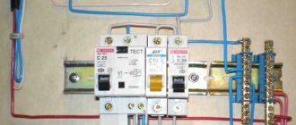
Let's take a look at the router ports and everything will become clear to you right away. Most often, such devices have at least 1 LAN port for connecting a local device. There are 4 of them in the picture above. And here we can connect a laptop, computer, TV or network printer. They will all be on the same local network.
But there is one more input, which usually stands out from the rest and has the inscription “WAN”. WAN or Wide Area Network is a global network. Usually a cable from the provider is inserted there and the Internet connection comes from this port.
NOTE! Sometimes ports have other designations: “LAN” - “Ethernet”, and “WAN” - “Internet”. The names are similar, but have different purposes.
You can see the general diagram above. The cable from the provider goes to the WAN port. Next, after setting up the Internet and connecting to the router, all connected devices to the local network will have access to the global network. I told you some basic things, but if you want to learn more about LAN and other connections, then feel free to go here.
Standard
The TIA/EIA 568-A standard, which was ratified in 1995, was replaced by the TIA/EIA 568-B standard in 2002 and has since been updated. Both standards specify the T-568A and T-568B outputs to use unshielded twisted pair cable and RJ-45 connectors for Ethernet connections. Both T-568A and T-568B standards are the most commonly used in Ethernet connections. The prefix RJ stands for Registered Jacks. RJ-11 is a 6-position, 4-wire jack used in telephone wiring, while RJ-45 is an 8-position, 8-wire jack used in 10BaseT and 100BaseT ethernet wiring.
Learn more about end-to-end and cross-connections
T-568A and T-568B are two wiring standards for the RJ-45 data cable specified in the TIA/EIA-568-A wiring standards document. The difference between them is the location of the orange and green wires. It is preferable to connect to T-568B standards, since this standard is very popular and widespread.
To create a straight-through cable, you need to use either T-568A or T-568B on both ends of the cable. To create a crossover cable, you can connect a T-568A on one end and a T-568B on the other end of the cable.
Straight-through cables are used when connecting data termination equipment (DTE) to communications equipment (DCE), such as computers and routers, modems (gateways), or hubs (Ethernet switches). Crossover cables are used when connecting DTE to DTE or DCE to DCE equipment such as a computer and a router. Or a gateway to hub connections.
To connect two computers without a hub, use a crossover cable.
A crossover cable is also used to connect a router to a computer or an Ethernet switch (hub) to another Ethernet switch without an uplink. Most Ethernet switches today provide an uplink port that prevents a crossover cable from being used to daisy-chain another Ethernet switch. Wired cables are used to connect a computer to an Ethernet switch or a router to an Ethernet switch. Pinout
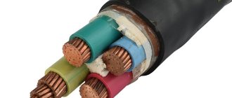
What is twisted pair
The name twisted pair comes from the fact that the cable has 8 copper conductors twisted in pairs of different colors.
Twisting is carried out in order to reduce the influence of external electromagnetic interference and mutual interference during signal transmission.
Using twisted pair, you can create a connection with data transfer rates of up to 1 GB per second. To create a high-speed network, you must have a cable with 8 wires, that is, 4 twisted pairs. For this reason, it is recommended to crimp all 8 wires. But there are also cables designed for 4 cores.