A radio amateur who has encountered the type of SMD capacitor for the first time is perplexed as to how to understand all these “squares” and “barrels” if some do not have markings at all, and if there is one, you won’t understand what it means. But you want to keep up with the times, which means you still have to figure out how to determine the identity of a board element and distinguish one component from another. As it turned out, there are still differences, and the markings, although not always and not on all capacitors, give an idea of the parameters. There are, of course, SMD components without identification marks, but first things first. First you need to understand what this element is and what its task is.
This component works as follows. Each of the two plates located inside is supplied with opposite charges (their polarities differ), which tend to one another according to the laws of physics. But the charge cannot “penetrate” onto the opposite plate due to the fact that there is a dielectric spacer between them, and therefore, not finding a way out and not being able to “escape” from the nearby opposite pole, it accumulates in the capacitor until its capacity is filled.
Introduction
The modern radio amateur now has access to not only ordinary components with leads, but also such small, dark parts that you can’t understand what’s written on them. They are called "SMD". In Russian this means “surface mount components”. Their main advantage is that they allow the industry to assemble boards using robots that quickly place SMD components in their places on the printed circuit boards, and then mass bake them to produce assembled printed circuit boards. The human share remains with those operations that the robot cannot perform. Not yet.
The use of chip components in amateur radio practice is also possible, even necessary, as it allows you to reduce the weight, size and cost of the finished product. Moreover, you practically won’t have to drill.
For those who first encountered SMD components, confusion is natural. How to understand their diversity: where is the resistor, and where is the capacitor or transistor, what sizes do they come in, what types of SMD parts are there? You will find answers to all these questions below. Read it, it will come in handy!
Electrolytic
These surface mount components consist of:
Various models of these components, rated from 1 to 1000-150 μF, are capable of operating at voltages from 4 to 1000 V.
Passive components: Electrolytic capacitors
| TYPE: | Type Explanation: | ||||
| S.E. | Aluminum Capacitor Aluminum capacitor (polar component) | ||||
| Case diameter | Case height | Tape width | Component pitch in the ribbon | Qty per standard package (180 mm/7 inches) plastic tape | Qty per standard pack (330 mm/13 inches) plastic tape |
| 3 mm | 5.5 mm | 12 mm | 8 mm | 100 | 2000 |
| 4 mm | 5.5 mm | 12 mm | 8 mm | 100 | 2000 |
| 5 mm | 5.5 mm | 12 mm | 12 mm | 100 | 1000 |
| 6.3 mm | 5.5 mm | 16 mm | 12 mm | 100 | 1000 |
| 8 mm | 6 mm | 16 mm | 12 mm | 100 | 1000 |
| 8 mm | 10 mm | 24 mm | 16 mm | 100 | 500 |
| 10 mm | 10 mm | 24 mm | 16 mm | 100 | 300 — 500 |
| 10 mm | 14 - 22 mm | 32 mm | 20 mm | — | 250 — 300 |
| 12.5 mm | 14 mm | 32 mm | 24 mm | — | 200 — 250 |
| 12.5 mm | 17 mm | 32 mm | 24 mm | — | 150 — 200 |
| 12.5 mm | 22 mm | 32 mm | 24 mm | — | 125 — 150 |
| 16 mm | 17 mm | 44 mm | 28 mm | — | 125 — 150 |
| 16 mm | 22 mm | 44 mm | 28 mm | — | 75 — 100 |
| 18 mm | 17 mm | 44 mm | 32 mm | — | 125 — 150 |
| 18 mm | 22 mm | 44 mm | 32 mm | — | 75 — 100 |
| 20 mm | 17 mm | 44 mm | 36 mm | — | 50 |
Features of PCB Design
Solid tantalum capacitors do not impose any specific restrictions on the PCB material. All generally accepted materials can be used: FR4, FR5, G10, aluminum boards, fluoroplastic (PTFE) boards.
The shape and size of the pads are usually provided by the capacitor manufacturers. The seat drawing is accompanied by an indication of the installation method.
If you need to use a shape or size of pads different from those recommended, you should take care to fine-tune the installation process. This may require adjustment of soldering temperature conditions.
Marking of Electrolytic SMD capacitors
SMD electrolytic capacitors are often marked by their capacitance and operating voltage, for example 10 6V
– 10 µF 6V. Sometimes this code is used instead of the usual one, which consists of a symbol and 3 digits. The symbol indicates the operating voltage, and 3 digits (2 digits and a multiplier) give the capacitance in pF.
A slice or stripe indicates a positive terminal.
| Symbol | Voltage |
| e | 2.5 |
| G | 4 |
| J | 6.3 |
| A | 10 |
| C | 16 |
| D | 20 |
| E | 25 |
| V | 35 |
| H | 50 |
For example, the capacitor is marked A475 – 4.7mF 10V
475 = 47 x 10^5pF = 4.7 x 10^6pF = 4.7mF
The following coding principles are used by such well-known companies as PANASONIC, HITACHI, etc. There are three main coding methods.
A
. The code contains two or three characters (letters or numbers) indicating the operating voltage and rated capacity. Moreover, the letters indicate voltage and capacitance, and the number indicates the multiplier. In the case of a two-digit designation, the operating voltage code is not indicated.
IN
. The code contains four characters (letters and numbers) indicating the rated capacity and operating voltage. The letter at the beginning indicates the operating voltage, subsequent characters indicate the capacitance in picofarads (pf), and the last digit indicates the number of zeros.
There are 2 options for encoding the capacitance: a) the first two digits indicate the nominal value in pF, the third - the number of zeros; b) the capacitance is indicated in microfarads, the p sign acts as a decimal point.
Below are examples of marking capacitors with a capacity of 4.7 μF and an operating voltage of 10 V.
WITH
. If the size of the case allows, then the code is located in two lines: the capacitance rating is indicated on the top line, and the operating voltage is indicated on the second line. Capacitance can be indicated directly in microfarads (uF) or 8 picofarads (pf) indicating the number of zeros (see method B). For example, the first line is 15, the second line is 35V means that the capacitor has a capacity of 15 uF and an operating voltage of 35 V.
The marking of capacitors is of great importance for the correct selection of a particular element in various circuits. Compared to, it is quite complex and varied. Particular difficulties arise when reading the markings on the housings of small capacitors due to the small surface area. A qualified specialist who constantly uses these devices in his work must confidently read the product labeling and decipher it correctly.
Capacitor markings: decoding numbers and letters
Depending on the type of storage device, there are several methods for marking them.
Marking of ceramic devices
Devices of this type are marked with one or two Latin letters and a number. The first letter denotes the manufacturer of the component, the second – its nominal capacity. The number in the marking code indicates the capacitor rating in picofarads.
Example. The marking of the storage SMD component KG3 stands for a product manufactured and having a capacity of 1.8 × 10³ pF.
Marking of electrolytic SMD drives
Surface mount electrolytic storage devices are labeled in 4 main ways:
- In the form of one letter indicating the operating voltage and three numbers, two of which indicate the capacitance value of the capacitor, and the third - the degree of rating in picofarads.
- In the form of two letters indicating the operating voltage and capacitance, one number indicating the degree of rating in picofarads.
- Four-character is a designation consisting of one letter indicating the operating voltage, two numbers indicating the component's capacitance, and a final digit indicating the number of zeros after the capacitance value.
- Two-line - the upper part of the marking in the form of a number indicates the capacity of the component, the lower part indicates its operating voltage.
Marking of tantalum storage SMD devices
The marking of tantalum SMD drives consists of the following parts:
- A capital letter indicating the operating voltage of the component;
- A three-digit number, the first two digits of which indicate the storage capacity, and the last - the number of zeros after the capacity value.
Example. The marking of the G103 tantalum drive means that it has an operating voltage of 4 V and a capacity of 10,000 picofarads.
Marking of Ceramic SMD capacitors
Due to their small size, SMD ceramic capacitors are sometimes marked with a code consisting of one or two characters and a number. The first character, if any, is the manufacturer's code (eg K for Kemet, etc.), the second character is the mantissa and the digit exponent (multiplier) of the capacitance in pF. For example S3 is a 4.7nF (4.7 x 10^3 Pf) capacitor from an unknown manufacturer, while KA2 is a 100 pF (1.0 x 10^2 PF) capacitor from Kemet.
| Letter | Mantissa | Letter | Mantissa | Letter | Mantissa | Letter | Mantissa |
| A | 1.0 | J | 2.2 | S | 4.7 | a | 2.5 |
| B | 1.1 | K | 2.4 | T | 5.1 | b | 3.5 |
| C | 1.2 | L | 2.7 | U | 5.6 | d | 4.0 |
| D | 1.3 | M | 3.0 | V | 6.2 | e | 4.5 |
| E | 1.5 | N | 3.3 | W | 6.8 | f | 5.0 |
| F | 1.6 | P | 3.6 | X | 7.5 | m | 6.0 |
| G | 1.8 | Q | 3.9 | Y | 8.2 | n | 7.0 |
| H | 2.0 | R | 4.3 | Z | 9.1 | t | 8.0 |
Capacitors are manufactured with different types of dielectrics: NP0, X7R, Z5U and Y5V…. The NP0(COG) dielectric has a low dielectric constant, but good temperature stability (TKE is close to zero). SMD capacitors of large ratings made using this dielectric are the most expensive. X7R dielectric has a higher dielectric constant, but lower temperature stability. Dielectrics Z5U and Y5V have a very high dielectric constant, which makes it possible to produce capacitors with a large capacitance value, but with a significant spread in parameters. SMD capacitors with X7R and Z5U dielectrics are used in general purpose circuits.
| Temperature Range | Changing Capacity | ||||
| First character | lower limit | Second character | Upper limit | Third character | Accuracy |
| Z | +10°C | 2 | +45°C | A | ±1.0% |
| Y | -30°C | 4 | +65°C | B | ±1.5% |
| X | -55°C | 5 | +85°C | C | ±2.2% |
| 6 | +105°C | D | ±3.3% | ||
| 7 | +125°C | E | ±4.7% | ||
| 8 | +150°C | F | ±7.5% | ||
| 9 | +200°C | P | ±10% | ||
| R | ±15% | ||||
| S | ±22% | ||||
| T | +22,-33% | ||||
| U | +22,-56% | ||||
| V | +22,-82% |
– capacitor with an accuracy of +22, -56% in the temperature range from +10 to +85°C.
X7R
– capacitor with an accuracy of ±15% in the temperature range from -55 to +125°C.
Resistors
Passive Components: Resistors
| TYPE: | Type Explanation: | |||||
| S.R. | Resistor Chip Resistor chip | |||||
| Size (inches) | Size(mm) | Component Thickness | Tape width | Component pitch in the ribbon | Quantity in standard packaging (180 mm/7 inches) paper tape | Qty per standard package (180 mm/7 inches) plastic tape |
| 01005 | 0402 | 0.12 mm ± 0.02 | 8 mm | 2 mm | 20000 | — |
| 0201 | 0603 | 0.23 mm ± 0.03 | 8 mm | 2 mm | 15000 | — |
| 0402 | 1005 | 0.35 mm ± 0.05 | 8 mm | 2 mm | 10000 | — |
| 0603 | 1608 | 0.45 mm ± 0.1 | 8 mm | 4 mm | 5000 | — |
| 0805 | 2012 | 0.55 mm ± 0.1 | 8 mm | 4 mm | 5000 | — |
| 1206 | 3216 | 0.55 mm ± 0.15 | 8 mm | 4 mm | 5000 | — |
| 1210 | 3225 | 0.55 mm ± 0.15 | 8 mm | 4 mm | 5000 | 4000 |
| 2010 | 5025 | 0.55 mm ± 0.15 | 8/12 mm | 4/8 mm | — | 4000 |
| 2512 | 6332 | 0.55 mm ± 0.15 | 12 mm | 4/8 mm | — | 4000/2000 |
Passive Components: Resistors
| TYPE: | Type Explanation: | ||||
| SRM | Melf Resistor Melf resistor (round) | ||||
| Size (inches) | Name | Component size | Tape width | Component pitch in the ribbon | Qty per standard package (180 mm/7 inches) plastic tape |
| 0604 | — | 1.6 mm X 1.0 mm | 8 mm | 4 mm | 3000 |
| 0805 | Micro | 2.2 mm X 1.1 mm | 8 mm | 4 mm | 3000 |
| 1206 | Mini | 3.2 mm X 1.6 mm | 8 mm | 4 mm | 3000 |
| 1406 | Mini | 3.5 mm X 1.4 mm | 8 mm | 4 mm | 3000 |
| 2308 | Melf | 5.9 mm X 2.2 mm | 12 mm | 4 mm | 1500 |
Designation in diagrams
In general, when repairing and re-soldering modern SMD printed circuit boards, it is most convenient when you still have a diagram at hand, looking at which it is much easier to understand what is installed, to find out the location of a certain part, because an SMD capacitor in appearance may not differ at all from the same transistor. The designations of these parts in the circuits remained the same as they were before the arrival of chips on the market, and therefore the capacity and other necessary characteristics can also be easily found by a radio amateur who has not encountered SMD components.
SDM capacitors without markings
> Theory > SDM capacitors without markings
When working with SMD capacitors, many radio amateurs encounter certain difficulties, since on the first try it is very difficult to understand the symbols on them. There are also capacitor products that are not marked at all.
As a result, the question of how to identify an smd capacitor without markings seems very important for all fans of installing radio equipment. But before learning to identify unmarked domestic and imported containers, it is advisable to familiarize yourself with their varieties.
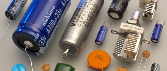
Types of SMD capacitors
Various names of SMD capacitors are divided into three classes according to their functional purpose:
- Ceramic or film non-polar products with ratings from 10 picofarads to 10 microfarads, which are usually not marked;
- Electrolytic capacitors shaped like an aluminum barrel designed for surface mounting;
- Tantalum capacitor parts having a rectangular body of various sizes. Available with color (black, yellow or orange) markings, supplemented by a special code.
All listed products must have a designation made in the form of markings that comply with the standard. But often it is missing for one reason or another (it is erased, washed off or was not applied during handicraft production). In this case, it is necessary to take some steps to fully identify them.
How to determine the rating and voltage
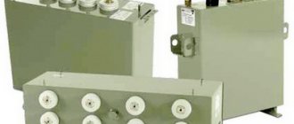
High voltage capacitors
Each miniature capacitor is characterized by two main parameters: the nominal capacity and the maximum voltage at which it can still operate. Let us consider the procedure for identifying each of these indicators in more detail.
Minus symbol
The principle of polarity marking of imported products differs from traditional standards of the domestic industry and consists of an algorithm. The location of the negative contact is indicated by both special symbols and the color of the housing.
For example, on a black cylindrical body, the negative terminal side, sometimes called the cathode, has a light gray stripe applied along the entire height of the cylinder. A dashed line, or elongated ellipses, or a minus sign is printed on the strip, as well as 1 or 2 angle brackets, pointed at the cathode at an acute angle. The model range with other denominations is distinguished by a blue body and a pale blue stripe on the side of the negative contact.
Other colors are also used for marking, following the general principle: dark body and light stripe. Such markings are never completely erased and therefore you can always confidently determine the polarity of the “electrolyte,” as electrolytic capacitors are called for brevity in radio engineering jargon.
The body of SMD containers, manufactured in the form of a metal aluminum cylinder, remains unpainted and has a natural silver color, and the segment of the round upper end is painted with an intense black, red or blue color and corresponds to the position of the negative terminal. After mounting the element on the surface of the printed circuit board, the partially painted end of the housing, indicating the polarity, is clearly visible on the diagram, since it has a greater height compared to flat elements.
The polarity designation of a cylindrical SMD device corresponding to the marking is applied to the surface of the board: this is a circle with a segment shaded with white lines where the negative contact is located. However, it should be noted that some manufacturers prefer to mark the positive contact of the device in white.
Electrolytic components
It is known that the marking of an electrolytic capacitor has its own characteristics, which are manifested in the indication of another additional parameter - the polarity of the inclusion. If this designation is missing, the only way to restore the lost information is to remove it from the circuit and determine the voltage polarity in this area using a multimeter.
Additional Information. Before soldering the identified product from the board, you should mark its legs in some way that allows you to fix their location in the circuit.
In conclusion, we note that for any type of capacitor product, determining the rating or operating voltage will require the ability to handle special measuring equipment.
Why is labeling needed?
The task of labeling is to ensure that each specific element corresponds to certain performance characteristic values. Capacitor markings include the following:
- in fact, capacity is the main characteristic;
- maximum permissible voltage value;
- temperature coefficient of capacity;
- permissible deviation of capacity from the nominal value;
- polarity;
- year of issue.
The maximum voltage value is important because when its value is exceeded, irreversible changes occur in the element, up to its destruction. Temperature coefficient of capacitance (TKE) characterizes the change in capacitance with fluctuations in the temperature of the environment or the element body
This parameter is extremely important when the capacitor is used in frequency-setting circuits or as a filter element
The temperature coefficient of capacitance (TKE) characterizes the change in capacitance with fluctuations in the temperature of the environment or the body of the element. This parameter is extremely important when the capacitor is used in frequency-setting circuits or as a filter element.
Tolerance means the accuracy with which the rated capacitance of capacitors can vary.
Connection polarity is mainly characteristic of electrolytic capacitors. Failure to observe the switching polarity, at best, will lead to the fact that the actual capacity of the element will be greatly underestimated, and in reality the element will almost instantly fail due to mechanical destruction as a result of overheating or electrical breakdown.
The greatest difference in the principles of marking capacitors is observed in radioelements produced abroad and by enterprises in the post-Soviet space. All enterprises of the former USSR and those that continue to operate now code their products according to a single standard with minor differences.
Structure and production technology
Tantalum and aluminum are priority metals in the production of capacitors. This is explained by the ability to regulate the thickness of the non-conducting oxide layer, which directly affects the capacitance. The capacitor itself consists of:
- positive (anode) and negative (cathode) electrodes;
- dielectric - oxide film;
- electrolyte - a conductive medium, in this case a solid state.
Capacitor structure The difference between tantalum and aluminum becomes clear if you understand the process of capacitor formation. The first feature is the anode. The compressed tantalum powder is heated in a vacuum to produce a characteristic “sponge.”
Dielectric Formation
The dielectric is obtained as a result of oxidation - a non-conducting film is formed on the surface. At this stage, the advantage of the metal appears: the thickness of the layer can be controlled by changing the applied voltage.
We advise you to study Natural lighting and requirements for it
Solid state electrolyte
Manganese dioxide is used. The production technology is as follows:
- A “sponge” with a dielectric tantalum layer is impregnated with manganese salts.
- The structure is subjected to heat treatment. This is necessary for the formation of dioxide.
The procedure is repeated several times until the surface is completely covered with electrolyte.
Features of the cathode of a tantalum capacitor
The negative electrode also deserves attention. The contact of the electrolyte with the cathode is improved using a layer of graphite coated with silver. Therefore, tantalum itself is not the only rare and expensive material in production.
ESR tantalum capacitors
Equivalent resistance (ESR) is determined by frequencies:
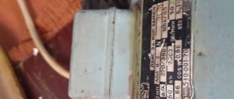
How are large capacitors marked?
To correctly read the technical specifications of a device, some preparation is necessary. You need to start studying with units of measurement. To determine capacitance, a special unit is used - farad (F). The value of one farad for a standard circuit seems too large, so household capacitors are marked in smaller units. The most commonly used is mF = 1 µF (microfarad), which is 10 -6 farads.
In calculations, an off-label unit can be used - millifarad (1mF), which has a value of 10 -3 farads. In addition, designations can be in nanofarads (nF) equal to 10 -9 F and picofarads (pF) equal to 10 -12 F.
Large size markings are applied directly to the body. In some designs, the markings may differ, but in general, you need to be guided by the units of measurement mentioned above.
Designations are sometimes written in capital letters, for example, MF, which actually corresponds to mF - microfarads. The marking fd is also found - an abbreviation of the English word farad. Therefore mmfd will correspond to mmf or picofarad. In addition, there are designations that include a number and one letter. This marking looks like 400m and is used for small capacitors.
In some cases, it is possible to apply tolerances, which are an acceptable deviation from the rated capacitance of the capacitor. This information is of great importance when, when assembling certain types of electrical circuits, capacitors with precise capacitance values may be required. If we take the marking 6000uF + 50%/-70% as an example, then the maximum capacitance value will be 6000 + (6000 x 0.5) = 9000 uF, and the minimum 1800 uF = 6000 - (6000 x 0.7).
If there are no percentages, you need to find the letter. Usually it is located separately or after the numeric designation of the container. Each letter corresponds to a specific tolerance value. After this, you can begin to determine the rated voltage.
With large capacitor housing sizes, voltage markings are indicated by numbers followed by letters or letter combinations in the form V, VDC, WV or VDCW. The WV symbols correspond to the English phrase WorkingVoltage, which means operating voltage. Digital readings are considered to be the maximum permissible capacitor voltage, measured in volts.
If there is no voltage marking on the device body, such a capacitor should only be used in low-voltage circuits. In an AC circuit, use a device designed specifically for this purpose. Capacitors designed for direct current cannot be used without the ability to convert the rated voltage.
The next step is to identify the positive and negative symbols that indicate the presence of polarity. Determining the positive and negative is of great importance, since incorrect determination of the poles can lead to a short circuit and even explosion of the capacitor. In the absence of special markings, the device can be connected to any terminals, regardless of polarity.
The pole designation is sometimes applied in the form of a colored stripe or a ring-shaped indentation. This marking corresponds to the negative contact in electrolytic aluminum capacitors, which are shaped like a tin can. In tantalum capacitors with very small dimensions, these same symbols indicate positive contact
If there are plus and minus symbols, the color coding can be ignored
power determination by color marking
Like resistors, capacitors are essential elements of any electronic circuit. If they are miniature, then there are difficulties in marking the parameters directly on the body. There are codes for this.
Appearance of tantalum capacitors
Tantalum capacitors
Tantalum capacitors are pole elements that use a tantalum anode electrode with a thin insulating oxide layer as the dielectric. They have a solid or liquid electrolyte that forms the cathode. Such parts provide high capacity for a small volume combined with low weight. Recently, manganese oxide in them has been replaced with a polymer material, which has made them safe and used in circuits with high currents.
Given the ongoing trend of miniaturization in electronics, tantalum capacitor element suppliers are packing ever larger capacitances into shrinking packages. KEMET already produces components with dimensions of 1x1.8x0.8 mm.
Tantalum elements are widely used in mobile devices and automotive electronics. They are used in cloud device holding circuits to prevent data loss even in the event of a power failure. Polymer parts are particularly suitable for these applications due to their long service life and high energy density.
Marking of tantalum elements
There are several developed codes for tantalum capacitors. Old details were encrypted using colors. Recently, numerical and alphabetic codes have been applied.
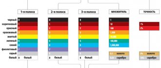
Color coding of tantalum capacitors
The color code consists of three stripes and a dot:
- the upper two bars are the capacitance value;
- a dot, or a colored spot, is the coefficient by which the value encoded in two stripes is multiplied;
- the third band is the operating voltage.
Important! The positive output is determined by the position of the colored spot. If you turn the surface of the housing with a point towards you, then the left contact is considered to be the positive pole.
Markings of numbers and letters for tantalum capacitors can be of several types:
- Two-digit code. The identifier consists of a letter followed by a number. Capital letters correspond to the capacity value of the standard E24 series with a tolerance of ±5%. If the code begins with a small letter, then this is a special value in a different gradation. The resulting capacitance value is to multiply the picofarads when decoding by an exponent of 10 to the power of n. Examples: S4 = 4.7 pF x 10000 = 47 nF, a5 = 2.5 pF x 100000 = 250 nF, W9 = 6.8 pF x 0.1 = 0.68 pF;
- Three-digit code. The containers are taken from the same standard E24 series with a tolerance of ±5%. The first two digits are multiplied by 10 to the power of the third number. If the third number is 8 or 9, this corresponds to a multiplier of 0.01 and 0.1. Examples: 479 = 47pF x 0.1 = 4.7 pF, 564 = 56 pF x 10000 = 560 nF, 105 = 10pF x 100000 = 1 µF;
Decoding the letter designations of the container
- A short three-digit code consisting of a small letter and numbers is read depending on the letter that designates the capacitive unit. By its position you can judge the decimal place. Examples: p22 = 0.22 pF, 56p = 56 pF, 4n7 = 4.7 nF, μ1 (0) = 0.1 µF = 100 nF.
Marking for tantalum SMD capacitors
On capacitors of significant dimensions, the capacitance and voltage values are not coded. Basically, alphanumeric encryption consists of two numbers and a letter. It is important to distinguish between tantalum and aluminum electrolytic capacitors. For SMD tantalum capacitors, the base capacitance value is in pF, and the positive terminal is marked with a wide stripe. For aluminum elements, the base capacitance is microfarads, and the negative pole is equipped with a black stripe.
Tantalum SMD capacitors
The four-digit code that marks the marking of tantalum SMD capacitors is deciphered as follows:
- the first two numbers are the capacitance in pF;
- third – multiplying factor;
- the letter at the end or at the beginning indicates the voltage value.
Important! Often the voltage is printed directly.
Voltage codes for SMD tantalum:
- e – 2.5B;
- G – 4B;
- J – 6.3B;
- A – 10B;
- C – 16B;
- D – 20B;
- E – 25B;
- V – 35B;
- H – 50B.
Tantalum SMD capacitors are used in circuits where it is necessary to provide large capacitances with compactly sized parts. The development of coding systems makes it possible to mark elements as small as desired, guaranteeing rapid identification.
Video
Rate the article:
elquanta.ru
What you will need
A multimeter is required during the measurement process. It is advisable that it measures capacitance.
In addition, you will need:
- 9 Volt adapter;
- screwdriver;
- tweezers;
- if the capacitor is on the board, then you will need a soldering iron with solder and flux.
Resistance measurement
It is impossible to check the element 100% without desoldering it from the board. This should be kept in mind when testing a part on a computer motherboard. Other details will interfere with proper verification. The only thing you can do is make sure there is no breakdown. To do this, touch the leads of the capacitor with probes and measure the resistance.
The resistance measurement will differ depending on the type of capacitor.
Electric capacitor
To test an electrolytic capacitor with a multimeter, follow these steps:
- Discharge the part by shorting both poles with tweezers or a screwdriver.
- Set the multimeter (ohmmeter scale) to the maximum measurement range and connect it to the capacitor, observing the polarity. The arrow of the device should deviate by a certain value, and then “go” to infinity.
Ceramic capacitor
To test a ceramic capacitor, set the maximum measurement limit. The multimeter will show a value of more than 2 MoM. If it is less, the device is faulty.
Tantalum capacitor
To make sure that the tantalum element is in good condition, connect the probe to the contacts of the capacitor, set the limit to the maximum. It should be measured in ohms. If the continuity test shows “0”, it means that the component is broken and needs to be replaced.
SMD capacitors
SMD elements are tested in a similar way to ceramic parts.
Measuring capacitance with a multimeter
A multimeter capable of determining the capacitance value of a capacitor will also be of great help here.
To measure you should do:
- Switch the device to measurement mode.
- Set the appropriate limit and connect the probes to the contacts. The device readings must correspond to the inscription on the element body.
- Take the adapter and, observing the polarity, connect it to the pins of the part (it needs to be unsoldered from the board). It will charge in a few seconds.
- Then connect the tester probes to the part and measure the voltage. At first, it should match what is indicated on the adapter.
How to determine the rating and voltage
Many manufacturers do not indicate on their products such basic characteristics for any capacitor as operating voltage and rating (nominal capacity).
The rating of these electronic components is determined in the following ways:
- Using a measuring instrument such as a multimeter that has the function of measuring the nominal value. To measure the nominal value, the control probes of the device are connected to special connectors. Then the switch is set to the largest measurement limit (in most multimeters this is 200 µF). After this, the probes are applied to the contacts of the capacitor; after a few seconds, the value of the storage device’s rating is shown on the device’s display.
Types of capacitors
Capacitors vary in type, there are only three of them:
- Ceramic, film and similar non-polar ones are not marked, but their characteristics are easily determined using a multimeter. Capacitance range from 10 picofarads to 10 microfarads.
- Electrolytic - produced in the form of an aluminum barrel, marked, in appearance they resemble ordinary input ones, but are mounted on the surface.
- Tantalum – rectangular body, different sizes. Issue color: black, yellow, orange. Marked with a special code.
Electrolytic components
Such SMD components are usually marked with capacitance and operating voltage. For example, it could be 156v, which would mean that its characteristics are 15 microfarads and a voltage of 6 V.
Or it may turn out that the marking is completely different, for example D20475. A similar code defines a capacitor as 4.7 µF 20 V. Below is a list of letter designations along with their voltage equivalent:
- e – 2.5 V;
- G – 4 V;
- J – 6.3 V;
- A – 10 V;
- C – 16 V;
- D – 20 V;
- E – 25 V;
- V – 35 V;
- N – 50 V.
The bar, as well as the slice, shows the position of the “+” input.
Ceramic components
The marking of ceramic SMD capacitors has a wider number of symbols, although the code itself contains only 2-3 characters and a number. The first symbol, if present, indicates the manufacturer, the second indicates the rated voltage of the capacitor, and the number is the capacitance indicator in pF.
For example, the simplest marking T4 will mean that the capacitance of this ceramic capacitor is 5.1 × 10 to the 4th power pF.
The rated voltage designation table is presented below.
Marking of tantalum SMD capacitors
Such elements of standard sizes “a” and “b” are marked with a letter code according to the rated voltage. There are 8 such letters - these are G, J, A, C, D, E, V, T. Each letter corresponds to a voltage, respectively - 4, 6.3, 10, 16, 20, 25, 35, 50. It is followed by a capacitive code in pkF, consisting of three digits, the last of which will indicate the number of zeros. For example, the marking E105 indicates a capacitor of 1,000,000 pF = 10 μF, and its nominal value is 25 V.
Dimensions C, D, E are marked with a direct code, similar to the code for electrolytic capacitors.
The main difficulty is that at the moment, although there are generally accepted designation rules, some large and well-known companies are introducing their own designation and code system, which is radically different from the generally accepted one. This is done so that when repairing the printed circuit boards they produce, only original parts and SMD components are used.
What are tantalum capacitors?
Tantalum capacitors are charge storage devices on the surface of which an oxide layer is formed. Such products are in wide demand. The storage capacity of the capacitor largely depends on the initial characteristics of this layer.
Tantalum capacitors
When processing tantalum in production, it is quite simple to control the basic parameters:
- Thickness.
- Conductivity.
- Uniformity of structure.
Manufacturing of Tantalum Capacitors The main components in such designs are described as follows:
- Anode lead for soldering.
- Marking line.
- An anode made of granular tantalum, to which a layer of pentoxide is added.
- An oxide with electrolytic characteristics.
- Combined coating with silver and graphite.
- Adhesive silver layer.
- Output for soldering installation, involving a printed circuit board.
- The compound that forms the body.
Tantalum capacitors - what is this? The increased resistance is provided due to the amorphous nature of the oxide layer. Silver and graphite, on the contrary, improve conductivity. The dielectric breaks through if its heating is excessively high.
Attention! Independent restoration of the capacitor is permissible only in case of minor damage and defects, and features that exclude suitability for repair must also be taken into account.
Polarity of domestically produced capacitor
Unlike imported parts, old Soviet capacitive two-terminal devices are marked with either only a plus, or plus and minus at once. For model type K50-16, the polarity of the terminals is marked on the bottom platform. It is marked next to the terminals, or the contacts pass through the center of the symbol.
An example of a domestic capacitor with polarity marked on the bottom
The poles of capacitive elements that require precise polarity when connecting are best identified using a multimeter. The data obtained as a result of measurements eliminates errors in determining the marking of the terminals.
How to test a ceramic capacitor
Non-polar capacitors (ceramic, paper, etc.) are checked with a multimeter in a slightly different way:
- We set up the device to measure resistance.
- We set the maximum measurement limit.
- We touch the measuring leads to the contacts without touching them.
If, as a result of these actions, the resistance value on the device screen is greater than 2 MΩ. – the capacitor is OK. If the resistance reading obtained is less than 2 Mohms. – the element is faulty (the capacitor is broken or shorted). It needs to be replaced with a good one.
Remember that when measuring at maximum resistance modes, it is imperative to avoid touching conductive parts. This is due to the fact that the resistance of the human body is much less than the resistance of the capacitor. This resistance has a great influence on the accuracy of the measurement. The tester does not show the correct parameters.
Marking with 3 and 4 digits
- The measuring device is transferred to the capacitance measurement state.
- The probes are connected twice. The second time they are swapped.
- Record the result. Both readings are compared.
- If “0” appears on the screen the first time, and “-” the second time, then the device is absolutely working. If the readings are the same, then the device can be considered inoperative.
Useful tips Connection diagrams Principles of operation of devices Main concepts Meters from Energomer Precautions Incandescent lamps Video instructions for the master Testing with a multimeter
Marking SMD capacitors – Technopolis tomorrow
(The lion's share of information was borrowed from the portal https://kazus.ru)
Marking of ceramic SMD capacitors
Due to their small size, SMD ceramic capacitors are sometimes marked with a code consisting of one or two characters and a number. The first character, if present, is the manufacturer's code (eg K for Kemet, etc.
), the second symbol is the mantissa and the digit is the exponent (multiplier) of the capacitance in pF. For example S3 is a 4.7nF (4.7 x 10³ Pf) capacitor from an unknown manufacturer, while KA2 is a 100 pF (1.
0 x 102 PF) capacitor from Kemet.
| A | 1.0 | J | 2.2 | S | 4.7 | a | 2.5 |
| B | 1.1 | K | 2.4 | T | 5.1 | b | 3.5 |
| C | 1.2 | L | 2.7 | U | 5.6 | d | 4.0 |
| D | 1.3 | M | 3.0 | V | 6.2 | e | 4.5 |
| E | 1.5 | N | 3.3 | W | 6.8 | f | 5.0 |
| F | 1.6 | P | 3.6 | X | 7.5 | m | 6.0 |
| G | 1.8 | Q | 3.9 | Y | 8.2 | n | 7.0 |
| H | 2.0 | R | 4.3 | Z | 9.1 | t | 8.0 |
Capacitors are manufactured with different types of dielectrics: NP0, X7R, Z5U and Y5V…. The NP0(COG) dielectric has a low dielectric constant, but good temperature stability (TKE is close to zero). SMD capacitors of large ratings made using this dielectric are the most expensive.
X7R dielectric has a higher dielectric constant, but lower temperature stability. Dielectrics Z5U and Y5V have a very high dielectric constant, which makes it possible to produce capacitors with a large capacitance value, but with a significant spread in parameters.
SMD capacitors with X7R and Z5U dielectrics are used in general purpose circuits.
| Z | +10°C | 2 | +45°C | A | ±1.0% |
| Y | -30°C | 4 | +65°C | B | ±1.5% |
| X | -55°C | 5 | +85°C | C | ±2.2% |
| 6 | +105°C | D | ±3.3% | ||
| 7 | +125°C | E | ±4.7% | ||
| 8 | +150°C | F | ±7.5% | ||
| 9 | +200°C | P | ±10% | ||
| R | ±15% | ||||
| S | ±22% | ||||
| T | +22,-33% | ||||
| U | +22,-56% | ||||
| V | +22,-82% |
Examples:
Z5U is a capacitor with an accuracy of +22, -56% in the temperature range from +10 to +85°C.
X7R is a capacitor with ±15% accuracy in the temperature range from -55 to +125°C.
Marking of electrolytic SMD capacitors
The following coding principles are used by such well-known companies as PANASONIC, HITACHI, etc. There are three main coding methods.
A. The code contains two or three characters (letters or numbers) indicating the operating voltage and rated capacity. Moreover, the letters indicate voltage and capacitance, and the number indicates the multiplier. In the case of a two-digit designation, the operating voltage code is not indicated.
B. The code contains four characters (letters and numbers) indicating the rated capacity and operating voltage. The letter at the beginning indicates the operating voltage, subsequent characters indicate the capacitance in picofarads (pf), and the last digit indicates the number of zeros.
There are 2 options for capacity coding:
- the first two digits indicate the nominal value in pF, the third - the number of zeros;
- Capacitance is indicated in microfarads, the p sign acts as a decimal point.
Below are examples of marking capacitors with a capacity of 4.7 μF and an operating voltage of 10 V.
C. If the size of the case allows, then the code is located in two lines: the capacitance rating is indicated on the top line, and the operating voltage is indicated on the second line.
Capacitance can be indicated directly in microfarads (uF) or 8 picofarads (pf) indicating the number of zeros (see method B).
For example, the first line is 15, the second line is 35V means that the capacitor has a capacity of 15 uF and an operating voltage of 35 V.
Marking of tantalum SMD capacitors
The marking of tantalum capacitors in sizes A and B consists of a letter code for the rated voltage according to the following table:
| Letter | G | J | A | C | D | E | V | T |
| Voltage, V | 4 | 6.3 | 10 | 16 | 20 | 25 | 35 | 50 |
It is followed by a three-digit code for the capacitance rating in pF, in which the last digit indicates the number of zeros in the rating. For example, the marking E105 indicates a capacitor with a capacity of 1,000,000pF = 1.0uF with an operating voltage of 25V.
The capacity and operating voltage of tantalum SMD capacitors of sizes C, D, E are indicated by their direct notation, for example 47 6V – 47uF 6V.
Code and color marking of capacitors
Code and color marking of resistors
Ceramic components
In ceramic elements, porcelain or similar inorganic materials are used as a dielectric. The main advantage of such products is their resistance to high temperatures and the ability to produce products of extremely small sizes.
Important! SMD ceramic capacitors are also installed by soldering onto a printed circuit board.
Visually, such an element, as a rule, resembles a small brick to which contact pads are soldered at the ends.
Ceramic SMD capacitors
Unlike radio components of standard sizes, SMD elements of small size are first glued to the board, and only then the leads are soldered. In production, ceramic products of this type are installed by special automatic machines.
Marking of ceramic SMD capacitors
Small ceramic SMD capacitors are marked with an alphanumeric code consisting of 3 characters. The first indicates the minimum operating temperature, for example:
- Z - from 10 °C;
- Y - from −30 °С;
- X - from 55 °C.
Marking of SMD capacitors
The second symbol indicates the upper heating limit of the radio component:
- 2 - up to 45 °C;
- 4 - up to 65 °C;
- 5 - up to 85 °C;
- 6 - up to 105 °C;
- 7 - up to 125 °C;
- 8 - up to 150 °C;
- 9 - up to 200 °C.
The third character indicates the accuracy of the electronic component:
- A - up to ± 1.0%;
- B - up to ± 1.5%;
- C - up to ± 2.2%;
- D - up to ± 3.3%;
- E - up to ± 4.7%;
- F - up to ± 7.5%;
- P - up to ± 10%;
- R - up to ± 15%;
- S - up to ± 22%;
- T - up to ± 33%;
- U - up to ± 56%;
- V - up to ± 82%.
The capacity of small ceramic SMD capacitors is indicated in picofarads. To save the area of a small radio element, the main mantissa number is encoded in a letter of the Latin alphabet. The table below provides a complete list of such designations.
Table with encoded characters
After the number, the multiplier is indicated, for example, the designation on a ceramic capacitor X3 means that the capacitor has a capacity of 7.5 * 10 ^ 3 Pf.
Note! The code indicating the capacity of a ceramic SMD capacitor may be preceded by a Latin letter, which indicates the brand of the manufacturer of the electronic component.
If the area of this type of ceramic capacitor is large enough, then the dielectric type can be displayed on it. For this purpose the following are used:
- NP0. The dielectric constant of such an element is at an extremely low level. The main advantage of components of this type is their good resistance to sudden temperature changes. The disadvantage of elements that use this type of dielectric is their high price;
- X7R. Average quality dielectric. Products that use this type of insulator do not have excellent breakdown resistance characteristics, but in the average temperature range they are able to work significantly longer than many more expensive elements;
- Z5U. A dielectric with high electrical permeability values, but the downside of this indicator is that the capacitance error is too large;
- Y5V. The insulating material has approximately the same characteristics as Z5U. In terms of cost, this dielectric is the cheapest, so electrical components made on its basis are sold at the lowest prices.
You may be interested in this. What is the unit of measurement for current?
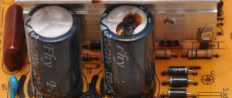
Burnt SMD capacitor
Considering all of the above, you can be sure that if the SMD capacitor has not burned or changed the color of the surface for other reasons, then you can always determine its value by the markings on its body.
Passive Components: Capacitors
| TYPE: | Type Explanation: | |||||
| S.C. | Ceramic Chip Capacitor | |||||
| Size (inches) | Size(mm) | Component Thickness | Tape width | Component pitch in the ribbon | Qty per standard package (180 mm/7 inches) paper tape | Qty per standard pack (180 mm/7 inches) plastic tape |
| 01005 | 0402 | 0.2 mm ± 0.03 | 8 mm | 2 mm | 20000 | — |
| 0201 | 0603 | 0.3 mm ± 0.03 | 8 mm | 2 mm | 15000 | — |
| 0402 | 1005 | 0.5 mm ± 0.1 | 8 mm | 2 mm | 10000 | — |
| 0603 | 1608 | 0.8 mm ± 0.1 | 8 mm | 4 mm | 4000 | — |
| 0805 | 2012 | 0.6 – 1.25 mm | 8 mm | 4 mm | 4000 | 3000 |
| 1206 | 3216 | 0.6 – 1.25 mm | 8 mm | 4 mm | 4000 | 3000 |
| 1210 | 3225 | 1.25 mm – 1.5 mm | 8 mm | 4 mm | — | 3000 |
| 1812 | 4532 | 2 mm (Max.) | 12 mm | 8 mm | — | 1000 |
| 2225 | 5664 | 2 mm (Max.) | 12 mm | 8 mm | — | 1000 |
Marking of imported capacitors
To designate imported, and in recent years, domestic radio elements, the recommendations of the IEC standard have been adopted, according to which a three-digit code marking is applied to the body of the radio element. The first two digits of the code indicate the capacitance in picofarads, the third digit is the number of zeros. For example, the numbers 476 indicate a capacitance of 47,000,000 pF (47 μF). If the capacitance is less than 1 pF, then the first digit is 0, and the symbol R is placed instead of a comma. For example, 0R5 – 0.5 pF.
For high-precision parts, a four-character encoding is used, where the first three characters determine the capacity, and the fourth - the number of zeros. The designation of tolerance, voltage and other characteristics is determined by the manufacturer.
Alphanumeric marking
With this marking, the letter indicates the decimal point and designation (uF, nF, pF), and the numbers indicate the capacitance value:
15p = 15 pF, 22p = 22 pF, 2n2 = 2.2 nF, 4n7 = 4.7 nF, μ33 = 0.33 µF
The letter R is also used for designation; it is used to designate capacitances in microfarads. And if there is a zero in front of “R”, then this means that the capacitance is in picofarads.
An example of alphanumeric marking of a designation:
0R5 = 0.5 pF, R47 = 0.47 µF, 6R8 = 6.8 µF
Features of the use of capacitor assemblies
Capacitor arrays are a group of capacitors that are structurally combined into one housing. Moreover, each of the elements can connect to the network independently of the others. Capacitor assemblies have found wide application in the creation of mobile and wearable equipment, motherboards, and radio frequency modems. They are also indispensable when assembling amplifiers.
Even though capacitors are extremely common, choosing a specific model can be quite difficult. Even if you know the capacitance and operating voltage ratings that are required for a particular design, there are other characteristics of components (polarity, temperature coefficients, stability, series equivalent resistance ratings) that make each specific type suitable only for certain solutions.
What are tantalum capacitors called?
The main difference from other types of devices is the use of the µ sign for capacity. The Latin letter v is added after the corresponding number to quickly understand what voltage the device has. There are also additional codes used for the following parameters:
- Manufacturer.
- Date of issue.
- Execution option.
Marking Studying the instructions and descriptions on the manufacturer’s official website will help you obtain additional information related to a particular capacitor model.
You should especially carefully study the step-by-step installation instructions for the product. For example, when installing on a printed circuit board, in most cases they use conventional manual soldering or infrared heating with a special camera. Important! To prevent destruction of the oxide layer and the occurrence of other defects, it is recommended to adhere to the permissible temperature range specified by the manufacturer.
Marking of SMD capacitors and their designations
A radio amateur who has encountered the type of SMD capacitor for the first time is perplexed as to how to understand all these “squares” and “barrels” if some do not have markings at all, and if there is one, you won’t understand what it means. But you want to keep up with the times, which means you still have to figure out how to determine the identity of a board element and distinguish one component from another. As it turned out, there are still differences, and the markings, although not always and not on all capacitors, give an idea of the parameters. There are, of course, SMD components without identification marks, but first things first. First you need to understand what this element is and what its task is.
This component works as follows. Each of the two plates located inside is supplied with opposite charges (their polarities differ), which tend to one another according to the laws of physics. But the charge cannot “penetrate” onto the opposite plate due to the fact that there is a dielectric spacer between them, and therefore, not finding a way out and not being able to “escape” from the nearby opposite pole, it accumulates in the capacitor until its capacity is filled.
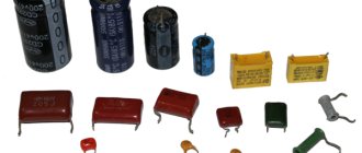
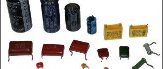
Types of capacitors
Different types of capacitors and polarity designation on them
Capacitors vary in type, there are only three of them:
- Ceramic, film and similar non-polar ones are not marked, but their characteristics are easily determined using a multimeter. Capacitance range from 10 picofarads to 10 microfarads.
- Electrolytic - produced in the form of an aluminum barrel, marked, in appearance they resemble ordinary input ones, but are mounted on the surface.
- Tantalum – rectangular body, different sizes. Issue color: black, yellow, orange. Marked with a special code.
Electrolytic components
Such SMD components are usually marked with capacitance and operating voltage. For example, it could be 156v, which would mean that its characteristics are 15 microfarads and a voltage of 6 V.
Or it may turn out that the marking is completely different, for example D20475. A similar code defines a capacitor as 4.7 µF 20 V. Below is a list of letter designations along with their voltage equivalent:
- e – 2.5 V;
- G – 4 V;
- J – 6.3 V;
- A – 10 V;
- C – 16 V;
- D – 20 V;
- E – 25 V;
- V – 35 V;
- N – 50 V.
The bar, as well as the slice, shows the position of the “+” input.
Ceramic components
The marking of ceramic SMD capacitors has a wider number of symbols, although the code itself contains only 2-3 characters and a number. The first symbol, if present, indicates the manufacturer, the second indicates the rated voltage of the capacitor, and the number is the capacitance indicator in pF.
For example, the simplest marking T4 will mean that the capacitance of this ceramic capacitor is 5.1 × 10 to the 4th power pF.
The rated voltage designation table is presented below.
Marking table for ceramic storage devices
Marking of tantalum SMD capacitors
Such elements of standard sizes “a” and “b” are marked with a letter code according to the rated voltage. There are 8 such letters - these are G, J, A, C, D, E, V, T. Each letter corresponds to a voltage, respectively - 4, 6.3, 10, 16, 20, 25, 35, 50. It is followed by a capacitive code in pkF, consisting of three digits, the last of which will indicate the number of zeros. For example, the marking E105 indicates a capacitor of 1,000,000 pF = 10 μF, and its nominal value is 25 V.
Dimensions C, D, E are marked with a direct code, similar to the code for electrolytic capacitors.
The main difficulty in marking such capacitors is that at the moment, although there are generally accepted designation rules, some large and well-known companies are introducing their own system of designations and codes, which is radically different from the generally accepted one. This is done so that when repairing the printed circuit boards they produce, only original parts and SMD components are used.
Designation in diagrams
In general, when repairing and re-soldering modern SMD printed circuit boards, it is most convenient when you still have a diagram at hand, looking at which it is much easier to understand what is installed, to find out the location of a certain part, because an SMD capacitor in appearance may not differ at all from the same transistor. The designations of these parts in the circuits remained the same as they were before the arrival of chips on the market, and therefore the capacity and other necessary characteristics can also be easily found by a radio amateur who has not encountered SMD components.
Design features of SMD resistors
The production of a chip resistor is the result of production using film technology. A layer of resistive coating in the form of a film of varying thickness is applied to the substrate. This substrate does:
- ensuring isolation;
- heat removal.
It is also the foundation. The resistance of such a chip directly depends on the material and thickness of the film coating. The complexity of working with thickness has led to two types of chip resistor manufacturing technology:
- Thick Film – thick film (70-10 microns);
- Thin Film – thin film (up to 50 nm).
The former are sometimes called cermet, due to the metal-oxide composition of the powders. Powder in the form of a paste is applied to the base and screen printing is used. After that, burning is carried out in a furnace, bringing the temperature to 9000 C.
The latter are made using ion vacuum deposition of a nickel-nichrome alloy. This achieves resistance accuracy with a tolerance of 0.01% in both directions.
Both types are ultimately adjusted to the specified resistance values using laser trimming (cutting).
It is difficult to distinguish externally what type of resistor it is. Thick Film Chip Resistors technology is somewhat simpler, which is why such elements are cheaper.
SMD resistor device
A passive two-terminal network with a certain resistance has a different shape. There are the following geometric varieties:
- rectangle;
- square;
- oval shape (low profile).
If we talk about the standard size of such circuit components, the JEDEC standard is mainly used. The standard size has a specific code that informs about the dimensions in length H and width W.
Table of sizes of SMD resistors
Conclusion
As a result of this lesson, I no longer just point out X7R or X5R types to colleagues or suppliers. Instead, I list specific batches from specific suppliers that I have tested myself. I also caution clients to double-check specifications when considering alternative manufacturing suppliers to ensure they do not encounter these problems. The main conclusion from this whole story, as you probably guessed, is: “read the datasheets!” Always. With no exceptions. Request additional information if the datasheet does not contain sufficient information. Remember that the designations for ceramic capacitors are X7V, Y5V, etc. They say absolutely nothing about their voltage coefficients. Engineers must double-check the data to know, really know, how the capacitors they use will perform under real-world conditions. So keep in mind, in our mad rush to get smaller and smaller, this is becoming more and more important every day.
Dimensions and types of SMD component housings
Two-pin components: rectangular, passive (resistors and capacitors)
The size designation consists of four digits. The first two correspond roundly to the length L in the accepted measurement system (either metric or inch), and the last two correspond to the width W.
| SD | Molded Tantalum Tantalum capacitor (polar component) | |||||
| Size (inches) | Code | Component Thickness | Component size | Tape width | Component pitch in the ribbon | Qty per standard package (180 mm/7 inches) plastic tape |
| 3216 | A | 1.6 mm | 3.2 mm X 1.6 mm | 8 mm | 4 mm | 2000 |
| 3528 | B | 1.9 mm | 3.5 mm X 2.8 mm | 8 mm | 4 mm | 2000 |
| 6032 | C | 2.5 mm | 6.0 mm X 3.2 mm | 12 mm | 8 mm | 500 |
| 7343 | D | 2.8 mm | 7.3 mm X 4.3 mm | 12 mm | 8 mm | 500 |
| 1608 | J | 0.8 mm | 1.6 mm X 0.8 mm | 8 mm | 4 mm | 4000 |
| 2012 | P/R | 1.2 mm | 2.0 mm X 1.2 mm | 8 mm | 4 mm | 2500/3000 |
| Size (inch system) | Size (Metric) | Size(mm) |
| 008004 | 0201 | 0.25×0.125 |
| 009005 | 03015 | 0.3×0.15 |
| 01005 | 0402 | 0.4×0.2 |
| 0201 | 0603 | 0.6×0.3 |
| 0402 | 1005 | 1.0×0.5 |
| 0603 | 1608 | 1.6×0.8 |
| 0805 | 2012 | 2.0×1.25 |
| 1008 | 2520 | 2.5×2.0 |
| 1206 | 3216 | 3.2×1.6 |
| 1210 | 3225 | 3.2×2.5 |
| 1806 | 4516 | 4.5×1.6 |
| 1812 | 4532 | 4.5×3.2 |
| 1825 | 4564 | 4.5×6.4 |
| 2010 | 5025 | 5.0×2.5 |
| 2512 | 6332 | 6.3×3.2 |
| 2725 | 6863 | 6.9×6.3 |
| 2920 | 7451 | 7.4×5.1 |
Two-pin components: cylindrical, passive (resistors and diodes) in MELF package
| frame | dimensions (mm) and other parameters |
| Melf (MMB) 0207 | L = 5.8 mm, Ø = 2.2 mm, 1.0 W, 500 V |
| MiniMelf (MMA) 0204 | L = 3.6 mm, Ø = 1.4 mm, 0.25 W, 200 V |
| MicroMelf (MMU) 0102 | L = 2.2 mm, Ø = 1.1 mm, 0.2 W, 100 V |
Two-terminal components: tantalum capacitors
| type | dimensions (mm) |
| A (EIA 3216-18) | 3,2 × 1,6 × 1,6 |
| B (EIA 3528-21) | 3,5 × 2,8 × 1,9 |
| C (EIA 6032-28) | 6,0 × 3,2 × 2,2 |
| D (EIA 7343-31) | 7,3 × 4,3 × 2,4 |
| E (EIA 7343-43) | 7,3 × 4,3 × 4,1 |
Two-terminal components: diodes (small outline diode, abbr. SOD)
| designation | dimensions (mm) |
| SOD-323 | 1,7 × 1,25 × 0,95 |
| SOD-123 | 2,68 × 1,17 × 1,60 |
Three-Terminal Components: Short Terminal Transistors (SOT)
Multi-pin components: terminals in two lines on the sides
| designation | pin spacing (mm) |
| IC - with small-outline integrated circuit (SOIC) | 1,27 |
| TSOP - (English thin small-outline package) thin SOIC (thinner in height than SOIC) | 0,5 |
| SSOP - Seated SOIC | 0,65 |
| TSSOP - Thin Seated SOIC | 0,65 |
| QSOP - Quarter Size SOIC | 0,635 |
| VSOP - even smaller QSOP | 0.4; 0.5 or 0.65 |
Multi-pin components: terminals in four lines on the sides
| designation | pin spacing (mm) |
| PLCC, CLCC - IC in a plastic or ceramic package with leads bent under the package in the form of the letter J | 1,27 |
| QFP - (English quad flat package) - square flat IC packages | different sizes |
| LQFP - low profile QFP | 1.4mm high different sizes |
| PQFP - plastic QFP (44 or more pins) | different sizes |
| CQFP - ceramic QFP (similar to PQFP) | different sizes |
| TQFP - thinner than QFP | thinner than QFP |
| PQFN - power QFP | no leads, pad for radiator |
Multi-Pin Components: Pin Array
| designation | pin spacing (mm) |
| BGA - (English ball grid array) - an array of balls with square or rectangular pinouts | 1,27 |
| LFBGA - low profile FBGA, square or rectangular, solder balls | 0,8 |
| CGA - package with input and output pins made of refractory solder | different sizes |
| CCGA - Ceramic CGA | different sizes |
| μBGA - (micro-BGA) - ball array | distance between balls less than 1 mm |
| FCBGA - (English flip-chip ball grid array) an array of balls on a substrate, a crystal with a heat spreader is soldered to the substrate | different sizes |
| PBGA - ball array, crystal inside a plastic case | different sizes |
| LLP - leadless package | — |