- UTP internet cables and telephone wires
- cable for the “Smart Home” system
- wires for acoustics
- alarm and video surveillance
- TV cable
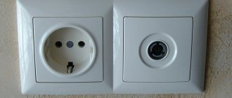
If earlier all this was simply thrown along the floor, behind furniture, in baseboards, today when renovating an apartment, walls are also tapped for low current and special sockets are installed.
Let's take a closer look at the installation of TV sockets from companies such as Schneider Electric (Unica series) and Legrand.
Connecting a TV socket Schneider Electric Unica
Technical characteristics of television connectors from Schneider Electric:
The decibel value indicates the weakening or attenuation of the signal.
The installation of all sockets must begin with cutting the coaxial cable. Leave a reserve of 10-15 cm in length in the socket box, cut off the rest.
Now the most important thing is to decide how much insulation needs to be removed. To what depth and how many centimeters?
It is best to take measurements directly on the outlet itself. To do this, take it in your hands, place the wire just below the inspection hole and mark with a marker or knife the cutting line at the level of the plastic central insert.
You can cut off the top layer of insulation using a specially designed tool.
as well as with a simple knife.
You can find an inexpensive stripper for coaxial cable on Ali Express here.
The screen under the insulation in television cables is found in different designs:
- only aluminum foil
- foil with copper braid
- one braid in the form of thin wires
If the total wire diameter is less than 7mm, the screen is often turned outward to ensure sufficient contact with the metal socket cover.
Just keep in mind that from the inside of the shell, the foil does not conduct current.
This is where the main mistake many electricians and television technicians make when connecting a coaxial cable - they hide all the wires of the screen behind this foil.
Therefore, at least half of its layer should be turned upside down. Otherwise, you simply will not have contact and no TV signal.
Removing the switch from the wall - what to pay attention to first
First, make sure you have special thin rubber gloves, without which it is not recommended to work. After this, you can proceed directly to the dismantling process. To properly remove the switch from the wall, you need to understand some of the features of the process.
Important points to highlight include:
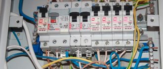
- Safety circuit breakers. The network is connected to the apartment through fuse plugs or current protection circuit breakers. Before starting work, it is imperative to turn off the voltage, for which the machine’s toggle switch is moved to the lower position. If there are plugs in the distribution panel, you will need to turn them off by pressing the red button located nearby, and also unscrew both plugs from the socket, which are responsible for the neutral wire and the phase.
- Type of switch. This is also a very important point. Today, many different models are used, which differ in additional functions - remote control, smooth adjustment, etc. However, for our problem, only the type of fastening matters - hidden (the switch box is recessed into concrete) and external (the box is screwed to the wall with screws). The first type is somewhat more complicated, so this is what we will talk about.
- Connection diagram. Most often, a light switch is equipped with several keys, which makes it difficult to remove the device from the wall, since the number of wires going to each key increases. In addition, the more keys, the more time it will take to remove each of these elements.
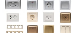
Types of TV sockets
Also pay attention to the icons and inscriptions on the case. There should be a symbol in the form of an arrow facing inward.
There is another arrow pointing upward.
If your model has 2 arrows facing in different directions, then this is a pass-through TV socket. That is, you run one cable from the antenna into the connector with a downward arrow, and with the other you release a cable or continue to pull the line to another connector, to another TV.
In general, there are 3 types of television sockets:
- single
- terminal - they have an additional resistor with a resistance of 75 Ohm (terminator)
- checkpoints
Single and terminal ones will transmit a signal of similar quality, provided that a TV is connected to them.
If you do not connect a TV to a single socket without resistance, then other TVs will experience interference and signal distortion. The terminals do not have this problem.
However, keep in mind that all this applies primarily to an analog signal. If you have digital TV, or are planning to switch to it, then problems may arise due to this resistor.
You will either have to throw out this outlet and replace it with another one, or connect it directly. These resistors dampen the signal very strongly. Some channels will show poorly or there will be no image at all.
All pass-through TV sockets have an inlet and an outlet. The output wire is connected to another outlet or directly to the TV. Their main disadvantage is the deterioration of the output signal by 4 dB.
Connection diagram for several TVs through pass-through sockets:
You should also initially pay attention to the signal transmission frequency of the outlet. Models with frequencies up to 1000 MHz are designed to work in networks with cable or terrestrial television. Instances with a frequency of over 1000 MHz are used for satellite television.
Possible mistakes
The most common mistakes when connecting a TV socket to a TV:
- Receptacles with 75 ohm resistors cannot be used for digital signal. This results in a very poor image, or no image at all.
- With an analog signal and connecting two or more TVs in series, excess resistance will also interfere and should be avoided.
- If there are empty sockets, you cannot use sockets without resistors in a series connection.
- Empty connectors on the network will also affect image quality. Try to use all TV sockets in the circuit.
- Insulating all screen veins with foil also reduces the signal quality. Foil is a poor conductor and the signal loses contact with the screen.
Did you like the article? Share 
0
Connecting the cable
To connect the cable, remove the insulation from the central core by 6-8mm. In this case, you need to retreat another couple of millimeters from the edge of the outer shell to the point where stripping begins.
Next, insert the TV wire into the socket and check through the viewing window that the central core goes all the way into the connector.
In the Unica series it is self-clamping, there is no need to tighten anything here. Other brands may have a clamping screw, which will need to be loosened first and then tightened with a screwdriver.
Pay special attention so that the “hairs” of the screen do not touch the central core anywhere.
All that remains is to tighten the cable itself with the central screw and put the outer cover in place.
If something is not clear and does not work out, you can always refer to the instructions.
What will you need for crimping?
Multimeter - to check the quality of crimping.
Video lesson: crimping an RJ connector Thanks to the advent of the Internet, many problems can be solved quite quickly, especially after watching videos. Stripper is a special hand tool for stripping insulation from conductors.
Almost all modern local networks use an RJ connector for connections.
Color scheme for crimping RJ 8P8C utp twisted pair cable computer - hub during repair If, when checking the twisted pair cable, a break or short circuit is detected in the orange or green twisted pair, and the blue and brown ones are working, then you can do without replacing the cable. To crimp such a cable, special RJ connectors are used. Their peculiarity is that you can connect more than one computer to one socket.
How to properly connect the Internet cable to an outlet. Connection diagram for RJ 45
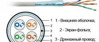
The protective insulation is removed from the cable by about a cm. Cables are divided into two types: shielded and unshielded and are designated as follows: Color schemes for crimping in an RJ plug There are several schematic solutions for crimping twisted pair cables, which will be discussed below using the example of an Internet cable, used to build LAN and DSL networks.
This connection method has become somewhat less widespread. You can also connect a ready-made patch cord to the equipment and check whether all packages are received. There is no need to strip thin wires.
Connecting Legrand Internet sockets with a cable (diagram)
In order to do this, you first need to unravel the wires and align them, and then lay them side by side in the correct sequence and press them together as tightly as possible. Cross crimping tool, used when connecting sockets, patch panels, etc.
Its length is left sufficient to carry out the necessary work. Moreover, such specialists will charge a considerable amount for this. This type of connection was demonstrated in Figure 12 V. How to connect two routers to the same network using a cable
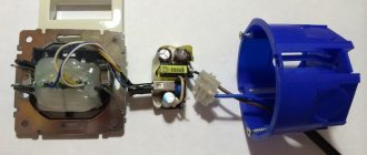
Connecting a Legrand Valena TV outlet
Installation of the socket, as usual, begins with its disassembly. The outer frame is attached here with latches. From the reverse side, press them with your fingers and remove the frame.
Next you need to get to the inside of the outlet. Insert a screwdriver into the slot and open the protective cover upwards.
Inside there is a seat for the central core. In front of it there is a wedge-shaped pin, which is driven under the top layer of insulation.
Strip the coaxial cable and expose the central core by 8mm. In this case, the outer screen remains completely under the insulation layer. There is no need to expose wires and foil .
Insert the cable into the socket so that the wedge penetrates under the outer shell of the insulating layer. The central core should go into its seat.
Again, note that there is no need to expose the screen here. The wedge-shaped stop itself goes under the insulation and forms contact.
Make sure that all contact parts of the socket and cable are in reliable contact with each other:
- central core in the seat
- wedge under insulation
- the wire is pressed tightly to the side frame
After this, close the lid with a simple movement. Next, the frame together with the cable can be easily rotated in different directions and mounted on the socket box.
How to disassemble a switch
So, in the initial position there is a key switch, which is firmly fixed inside the groove. First of all, you need to prepare a tool in order to disassemble the case - a screwdriver with an indicator, it will be enough.
The external light switch is disassembled as follows
:
- It is necessary to turn off the circuit breaker, which protects the wiring from electrical overloads and short circuits.
- Before dismantling, you need to make sure that there is no light in the house. And only after that you need to use a screwdriver with an indicator.
- Next, you need to dismantle the key if the switch is one-key or the keys if it is three-key or two-key. It doesn't matter what type of product is disassembled. To remove the key, you need to squeeze it with your hand from the sides (in the middle) and carefully remove it from the case. Sometimes the element “sits” firmly in the inside of the case, and in order to pull it out, you need to pick up one of the edges with a screwdriver.
- The next step is to remove the decorative frame and cover from the wall. Sometimes it is attached to two miniature bolts from the inside; less often, the frame is held in place by grooves that must be gently pressed with a screwdriver to remove the fittings. Another option for attaching electrical accessories is using an additional element that is attached to the grooves of the caliper.
- Next, you need to pull out the “core” from the socket box. There are two screws on the sides of the case that hold the mechanism on a vertical surface. All you need to do is unscrew them using an indicator screwdriver. There is another option for holding the case in the socket box - with claws. They need to be loosened by slightly unscrewing the bolts on the sides that are responsible for adjusting the thrust angle.
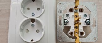
- The next step is to disconnect the input wires. Phase, ground and neutral can be fixed to self-clamping terminals or to a screw terminal. In the first case, you just need to press the locking levers and remove the wires from the connectors. The clamp screws must be unscrewed using an indicator screwdriver and the wiring carefully removed.
That's all, there is nothing complicated, the switch has been removed from the wall.
Connecting a cable without a TV socket
Is it possible to make a TV cable exit from the wall as neatly as with a socket, but without using it? You can, but you will still get 3 advantages of such a connection:
- no need to buy an expensive TV socket (cost savings reach up to 5 times the value!)
- there is no need to install a separate piece of cable to connect the TV connector to the outlet
- there is no degradation in signal quality. On the F connectors of the UHF range, the signal attenuates only from 0.1 to 0.3 dB.
All this is achieved by using ordinary plugs. Initially, lay a sufficient supply of cable in the wall so that it is enough for direct connection to the TV (1-1.5 meters).
Drill a hole in the plug to the diameter of the cable and bring the conductor out through it.
It all looks as beautiful as on an ordinary outlet.
The only negative is that not all manufacturers have this kind of plugs and may not be available on certain series.
Safety rules: how to remove the switch
2 main types of fastener designs for vertical surfaces inside a building have been developed, which differ: for hidden and for external electrical wiring.
To avoid the following errors:
:
- Short circuit.
- Failure of expensive lamps, energy-saving, LED or fluorescent light bulbs.
- Insulation burnout in the distributor or wall.
- Electric shock, which can be fatal.
Necessary: study the basic rules of safety measures. Before removing the switch, you need to familiarize yourself in detail with the design of the wall mounting and connection. Products for external electrical wiring are attached with traditionally standard fasteners; through the mounting holes, the housing is tightly attached to the vertical surface.
For internal wiring models Electric, Makel, Nilson or another brand, wall mounting technologies are more complex.
The design of the switch contains a mechanism of sliding bars, which create a fixation of the housing on two opposite sides in a hole made in advance with a size of 6.7-7 cm. Regardless of the type of switch and the purpose for which it needs to be removed, first of all on the distributor in the panel, it is necessary to turn off the protective machine. This must be done for safety reasons so that the person doing the dismantling or repair is not struck by an electric current.
You need to make sure that the shutdowns are performed correctly; to do this, you need to press the keys several times; the lamps should not light up. According to the requirements of the PUE, a warning sign must be installed on the circuit breaker in the distributor. Better yet, completely close the cabinet and take the keys for yourself while you work, so that strangers do not have access to the switchboard. Only by following this rule can you begin to disassemble the Legrand switch or any other (single, triple, double).
What could they be?
- TV-RD-SAT (Valena, Galea Life series). Used in cable television networks. They have three outputs for connecting a receiver (satellite), TV and radio.
- TV-FM-SAT (Celiane series). Used in TV cable networks. This is a star connection option, that is, each such device is directly connected to the TV splitter along one line. It distributes the signal to three connectors (outputs) for connecting a satellite, radio and television receiver.
- TV-RD (Galea Life series). Used in cable TV networks. Such sockets have two outputs for connecting a radio and television receiver. In this series, such a product is the final one.
The video below briefly explains the TV/RD (TV and Radio) and TV/RD/SAT (TV, Radio and Satellite) outlets.
Installation of TV sockets Legrand
How is the cable inserted into the TV socket?
On its back there is a terminal contact (screw). Usually it is located in the center. This contact is used to connect the TV cable (its central core). The braided screen is fixed with a specialized bracket (but if the sockets are pass-through, then there will be two such contacts, as well as brackets for making fixations). Before connecting the cable, its required length must be very carefully stripped. The braid and screen are slightly trimmed, then after connecting the central core of the cable, their remains are fixed with a bracket. When performing this operation, you need to control the entire process so that there is no short circuit between the core and braid. After this, the functionality of the connection is checked and the sockets are fixed into the already installed socket boxes.
How to connect Legrand STD TV 1?
First you need to prepare the cable (see previous question). After which it is inserted into a specific socket (mounting) on the disassembled TV socket. Then it is pressed with a lid, thus securing it, after which this device is already mounted in a pre-prepared hole on the wall surface.
What types of TV sockets are there?
We invite you to watch the video, which will tell you about two types of connecting television sockets: “star” and cable connection.
What plug is needed for the Legrand TV socket?
For these sockets, an F-plug (female) is used. It is screwed onto the corresponding connector, which is previously put on the cable (coaxial).
How to disassemble a Legrand TV socket?
Opening and repair of such products must be carried out by specialists who have received the necessary training from the manufacturer.
But to dismantle such devices, it is necessary:
- de-energize the room in which the socket will be removed (check the presence of current with a tester);
- Using a tool with insulated handles or rubber gloves, you can begin to remove the socket. To do this, remove the upper part of its box, then unscrew the fastening screw;
- The socket is pulled out of its niche on the wall surface, then the clamps (terminals) are loosened using a screwdriver, and the device is disconnected from the TV cable.
How to install a Legrand antenna splitter?
- Select the required splitter. It must have the required number of outputs adapted for F-connectors.
- We select the location for its installation and mark it on the diagram (the same as the location of TV receivers).
- After the cable is routed to the splitter, the outer sheath is removed from its end. The braid, as well as the foil screen, are separated from the center and bent to the uncleaned part of this cable. Its central part is also freed from insulation.
- A splitter nut is placed on the end of the cable. The braid and screen are folded back. The core (central) is inserted into a special socket at the splitter and tightened with a nut. Then the same operations are carried out with the remaining cable sections, after which the splitter is attached to a pre-selected location.
- The cable is brought to the television receiver, secured, if necessary, with specialized brackets or laid in plinth cable channels.
- Then the appropriately prepared cable (see above) is installed in the plug (a cap is put on it, the central wire is secured in it with a screw, the braid is crimped with a bandage) and the plug is inserted into the socket (antenna) of the television receiver.
How to install the Legrand TV socket?
If you do not have sufficient experience, then it is better to entrust the installation and connection of the Legrand socket to a specialist.
When installing and connecting an outlet, it is not recommended to lay the power and antenna cables next to each other. The distance between them should be at least 2 cm. Of course, in modern TVs the 50 Hz interference is quickly cut off, but it’s better to be on the safe side. If you are using a high quality antenna cable with excellent braiding, then this requirement is not critical.
Sockets for powering the TV, as well as for the antenna, are located nearby. If you need more 220 V sockets, then you can install a double socket option or more next to the antenna.
Where can I buy a TV x 3 divider for the F-connector 5-1000 MHz?
Such devices can be purchased from many specialized companies that sell electrical equipment and cables of various brands.
How to connect TV sockets in a star pattern?
There is only one entrance to the living space, but there are several televisions in modern apartments. In order to distribute a TV signal, it is necessary to use a specialized splitter device called a splitter, which has one input and 2-3 or more outputs. In this case, the connection diagram for TV sockets for televisions will be called “star”. As a rule, a cable with a fairly strong signal is included in a living space, but its power is not always enough for 2 or 3 TVs. If you are faced with such a problem and the signal strength is not enough, then you should provide power and a place to install a TV amplifier. It is better to place it as close as possible to the signal source.
The “star” scheme is used quite widely today because it has many advantages:
- cables exit from a single junction box to all necessary sockets;
- minimum level of TV signal attenuation;
- during a malfunction of one of all signal lines or sockets, the rest will operate normally.
It can also be noted that connecting to digital television, which has the best quality today, is only possible using the “star” system.
How to choose a Legrand TV socket?
It all depends on the number of devices used. For example, to connect one television receiver, one terminal or individual socket is enough. Multifunctional TV-RD devices are suitable for connecting radio and TV. To watch satellite TV, regular television programs and listen to radio, TV-RD-SAT, etc. are used.
How is a TV cable connected to a TV socket?
Before you start connecting a TV outlet, you should first figure out which device is needed - single or double or with a quarter connection.
Each socket has only two contacts, which are intended to power the connected electrical device - the working zero, as well as the phase.
Having selected the socket itself, you should perform the following actions, and you need to start with the correct movement of the PE wire from the floor panel. Initially, insert the wire itself into the junction box. After this, connect the remaining two wires to the RCD input, making sure that you have correctly connected the working zero, as well as the phase itself.
In the distribution box, each of the three wires must be located in such a way as indicated by the power supply diagram of a particular residential premises, that is, your home. Don't forget to familiarize yourself with the grounding contact, which is made in the form of a kind of shaped plate with a hole. The wire must be secured in this hole using the bolt located in the socket for fastening.
Each television socket has a screw contact on the back side, and, as a rule, it is located in the central part. It is necessary to connect the TV cable (central core). The braid with the screen must be fixed using a special bracket. It is very important to consider that if you are working with pass-through sockets, there will be two central contacts, so there should also be two brackets for fixation.
Before connecting the cable, it should be thoroughly stripped to the required length. The braid with the screen is cut off. After this, the central core of the cable is connected, and the excess screen along with the braid should be clamped using a clamp. The main task is to ensure that the central cable core and braid do not short-circuit. After this, you can check the functionality of the connection and fix the socket into the socket box.
What is a TV socket with feedback?
This is a multimedia device, which is a television socket (broadband), designed for a communication channel (return), which has outputs for TV and radio programs. Depending on the wiring (internal) and plugs, various analogue devices or ISDN devices can be connected to it. Such a complex not only provides access to the network using any outlet, but also performs various functions in housing: transferring the necessary data, telephony, connecting an intercom, etc.
How to disassemble a baseboard-type TV socket?
Electrical wiring is de-energized. Use a screwdriver to unscrew the screw holding the socket, remove the frame, and remove the disk that protects the device from children. Then the screws located on the terminals are disconnected and the wires are freed. By removing the screws that attract the base of the device to the plate, you complete the dismantling of the TV socket.
Removing the keys: how to remove the switch for wallpapering
To remove the wallpaper switch, you will need tools.
Namely
:
- Screwdriver – plus and minus;
- Indicator screwdriver;
- Portable lighting device.
Using a negative screwdriver, you need to remove the switch keys, for which you need to install its tip between the frame and one of the keys, above or below. With a little effort and using a screwdriver as a lever, you need to pry up the key and help with your hand to pull it out of the grooves. The second key can be removed freely. Using an indicator screwdriver, you need to make sure that there is no electrical voltage; to do this, it must be applied to each of the electrical contacts. If the switch is located in a dark place, you should use a flashlight or other portable light source so as not to damage the switch and special equipment.
After removing the keys, you can carry out any manipulations with the device, even under electrical voltage, naturally, observing the required safety measures.
They check the integrity of the electrical contacts and the presence of electrical voltage on them, after which they make a conclusion about whether the device is in working condition. When there is a need to dismantle the switch, for a more detailed inspection with disconnection from the power supply, or there is 100% confidence that the device needs to be replaced, then you should remove not only the keys, but also the retaining frame, which in turn holds the decorative frame. To do this, you need the same set of tools, but if the switch is attached using Phillips bolts, then in addition you will need to use a positive screwdriver.
The locking frame is located immediately below the keys, and can be removed using a minus screwdriver. It is attached to latches, they are present on the switch body, so you need to pry the teeth with a screwdriver and pull it towards you by hand. Once you have managed to open and remove it, you can begin decorating the room. After gluing, you need to assemble the switch. Assembly is carried out in reverse order.