August 23, 2011
Power electronics today is one of the most popular and rapidly developing areas of technology. The main trends in this industry include improving the power characteristics of control semiconductor devices and the use of intelligent control systems. Equally important is the desire for cost-effective and energy-saving solutions.
Vishay ESTA is one of the few global manufacturers offering almost a full range of power capacitors for various conditions and applications - filtering harmonics, reducing energy losses, stabilizing voltage, improving weight and size characteristics.
One of the target segments of the Vishay capacitor market is power generating installations, “green” technologies - wind power plants and solar panels.
In addition, Vishay power capacitors are used in high-, medium- and low-voltage power transmission and distribution networks. Their efficient operation makes it possible to reduce energy losses during transmission and, as a result, reduce CO2 emissions into the atmosphere.
Other applications include RFI filters, voltage converters in traction and industrial motors.
Capacitors for induction heating furnaces
The main function of power capacitors in induction heating furnaces is to adjust the operating circuits. Now, in addition to furnaces operating on industrial frequency currents (as a rule, these are high-power furnaces or furnaces of an old design), induction furnaces with semiconductor frequency converters (thyristor or transistor) are becoming more popular in use (and more economical). Two versions of stationary high-power semiconductor converters are implemented:
- Current inverter with parallel capacitor bank;
- Voltage inverter with series capacitor bank.
Vishay capacitors for induction heating furnaces (Fig. 1) meet the requirements of EN 60110/1 (2) and IEC 60110/1 standards.
Rice. 1. Capacitors for induction heating furnaces
Capacitors for industrial frequency networks (50/60 Hz) voltages 230...3000 V with power up to 800 kVar; for medium frequency - 150...100000 Hz, power up to 10000 kVar. Main series:
- Phao- 850…3000V (50/60Hz), single-phase with natural cooling, -25…40°C;
- Phao…/ m F- mid-frequency capacitors (~4000Hz) with natural cooling, -10…65°С;
- Phawo…k- 230…2500V, frequencies from 150 to 5000Hz, water cooling (outlet water temperature maximum 40°C), temperature range 1…50°C (pressure or temperature sensors can be connected);
- Phawo…kS- 230…3000V, frequencies from 150 to 10000Hz, with intermediate leads (up to 8), water cooling (outlet water temperature maximum 40°C), temperature range 1…50°C (pressure or temperature sensors can be connected);
- Phawo- 500…1000V, frequencies from 10 to 100 kHz, with intermediate leads (6), water cooling (outlet water temperature maximum 40°C), temperature range 1…50°C;
- Phawoz- 230...2500V, frequencies from 1000 to 10000Hz, with double outputs to increase the load, water cooling (outlet water temperature maximum 40°C), temperature range 1...50°C (pressure sensor can be connected);
- Phmkp- 230…525V (50/60Hz), single-phase with natural cooling, -25…40°C;
- Phmkp...-DR/Phmkpg...-DR- 200...1000V (50/60Hz), single-phase with natural cooling, -25...40°C, self-healing with emergency shutdown in case of overpressure or leakage.
Main advantages:
- Compact design;
- Adaptation to customer applications;
- Ability to work in extreme conditions;
- Ease of integration;
- Low inductance.
Technical implementation
The supercapacitor consists of two plates of activated carbon filled with electrolyte. Between them there is a membrane that allows the electrolyte to pass through, but prevents the physical movement of activated carbon particles between the plates.
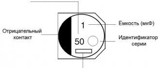
It should be noted that supercapacitors themselves have no polarity. In this they fundamentally differ from electrolytic capacitors, which, as a rule, are characterized by polarity, failure to comply with which leads to failure of the capacitor. However, polarity is also applied to supercapacitors. This is due to the fact that supercapacitors leave the factory assembly line already charged, and the marking indicates the polarity of this charge.
Capacitors for power electronics
Capacitors for power supplies, stabilizers, voltage or frequency converters operate under conditions of high switching currents, reactive loads, and with voltages of various forms. Typical applications include:
- Voltage converters in locomotives, electric trains, urban electric transport, industrial power supplies;
- DC power supplies;
- Industrial power supplies;
- High voltage line testing systems;
- Pulse arresters.
Capacitors offered by Vishay for power electronics (Fig. 2) meet the requirements of IE C 61071, IEC 61881 standards, and product adaptation to customer specifications is also possible.
Rice. 2. Capacitors for power electronics
The range of capacitors allows you to make the optimal choice for almost any type of application with AC voltage up to 24 kV, for DC voltage up to 125 kV with capacitor energy concentration levels up to 15 kJ.
The DCMKP series are low-inductance capacitors (<30 nH), capable of withstanding pulse currents up to 600 A, resistant to shock and vibration loads. Designed for voltage filtering, DC decoupling, energy storage in industrial and traction motors. Ratings 50...20000 µF, operation with voltage 900...4250 V.
EC, ET series are high-voltage capacitors made using combined dielectric technology (polyester, polypropylene, capacitor fabric) with oil filling in a sealed housing. Can be used in systems cooled by air, oil, or SF6 coolant. Designed specifically for high voltage filtration systems:
- Smoothing of voltage ripples;
- Induction furnace circuits;
- Power supplies for radio transmitters;
- Power supplies for X-ray machines.
Range of nominal values 1 nF…2 µF; (from 500 pF to 2 µF for the ET series), voltage range 1000...100000 V.
EMKP is a series of cylindrical capacitors with low losses at high frequencies for applications:
- In AC input/output filters;
- In devices for damping and reducing transient distortion;
- In load switching systems;
- For galvanic isolation and DC voltage filtering;
- Overvoltage protection.
Ratings 0.1...470 µF for operating voltages 400...2400 V.
The EPR series are high-voltage capacitors made using combined dielectric technology (polyester/polypropylene, capacitor fabric) with oil filling in a sealed polypropylene case with M10 bolt fastenings, resistant to mechanical shock and vibration.
Main intended use:
- Decoupling capacitors;
- High voltage arresters;
- Pulse sources;
- Radars, lasers, x-ray sources.
Ratings 2 nF...2 µF, range of possible operating voltages 1000...300000 V (DC voltage).
Capacitors for DC filters of the ER series combine good electrical characteristics with compact dimensions, are resistant to mechanical shock and vibration, and have a wide temperature range of -55...85°C.
Application oriented:
- In audio equipment;
- In switching power supplies;
- In generator circuits;
- When filtering radio interference;
- In custom filters;
- When smoothing out voltage ripples.
Ratings 10 nF...100 µF at voltages up to 30 kV.
GLI...A is a series of capacitors with low inductance and low losses at high frequencies (4x10⁻⁴ at 2 kHz), intended for voltage and frequency converters, industrial and traction motors, uninterruptible power supplies, and medical equipment. Ratings 1 pF...230 µF at voltages 700...2150 V.
HDKMP - capacitors for DC networks with a high level of rms current up to 150 A and peak current up to 25 kA, have low inductance and resistance to mechanical stress. The main target application is power filters in various power plants (traction engines, wind turbines, uninterruptible power supplies).
Advantages and disadvantages of capacitor products
What is an electric field?
The advantages of products of this class include:
- Low specific cost (per unit of capacity);
- High capacitive density and efficiency of charge-discharge cycles (up to 95% and above);
- Reliability, durability and environmental friendliness;
- Excellent power density;
- A fairly wide range of temperatures at which their operation is possible;
- The highest charge and discharge rate possible for products in this category;
- Acceptability of complete loss of capacity (almost to zero).
Another important advantage of SCs is their relatively small size and weight (compared to other types of electrolytic products).
SK sizes
Among their inherent “disadvantages” I would like to note the following disadvantages:
- Relatively low density of accumulated energies;
- Low voltage per unit of element capacity;
- High level of uncontrolled self-discharge.
Let's add to this the incompletely developed product production technology.
Low Voltage Capacitors for Power Electronics
Low-voltage (relatively, of course, “only” 230...1000 V) applications of capacitors include, first of all, compensation of voltage drops and filtering of harmonics in systems using power frequency currents (50...60 Hz). Designed to work with voltages in the range of 230...1000 V with energy levels of the order of 2.5...56.2 kVar for aluminum housings and up to 500 kVar in a steel housing. They are produced in series for indoor use - PhMKD and for outdoor conditions - PhMKDg (Fig. 3).
Rice. 3. Low voltage capacitors for power electronics
The advantages include low loss coefficient, compact size, good dissipation of excess heat, long MTBF (over 150,000 hours), compliance with EN 60831/1 and 2, EIC 60831/1 and 2 standards.
Application prospects
In the near future, the almost universal use of supercapacitors is expected, which will be implemented in most energy-intensive industries (including the medical industry, aerospace industry and military equipment).
Simultaneously with their introduction, the specific capacity of these products is increasing more and more, which in the future will make it possible to completely replace batteries with capacitors. The process of integrating supercapacitors into various structures of modern electronic production, including the manufacture of control and regulatory elements, is also planned.
In conclusion, we note that capacitor products of this class make it possible to introduce environmentally friendly methods of energy saving, which are much more promising than anything known so far. In the near future, further expansion of the scope of application of these technologies is expected, which could cover the entire motor transport industry, as well as communication devices and mobile equipment.
High Voltage Capacitors for Power Electronics
Main purpose:
- Shunt capacitors;
- Harmonic filtering;
- Series capacitors;
- Capacitors for static reactive power compensation;
- Capacitors for high-voltage DC power lines;
- Voltage limiters and filters.
Vishay high voltage capacitors are available up to voltage levels of 24 kV and power levels up to 900 kVar. Banks of capacitors are also offered that allow operating voltages up to 800 kV.
Available in versions with one and two contact sleeves, single- and three-phase capacitors are offered (Fig. 4).
Rice. 4. High voltage capacitors for power electronics
Design solutions make it possible to combine individual capacitors into banks and capacitor fields with protection against phase imbalance.
Using an electrical double layer
For many decades, electrolytic capacitors had the highest capacity. In them, one of the plates was metal foil, the other was an electrolyte, and the insulation between the plates was metal oxide, which coated the foil. For electrolytic capacitors, the capacity can reach hundredths of a farad, which is not enough to fully replace the battery.
Comparison of designs of different types of capacitors (Source: Wikipedia)
Large capacitance, measured in thousands of farads, can be obtained by capacitors based on the so-called electrical double layer. The principle of their operation is as follows. An electric double layer appears under certain conditions at the interface of substances in the solid and liquid phases. Two layers of ions are formed with charges of opposite signs, but of the same magnitude. If we simplify the situation very much, then a capacitor is formed, the “plates” of which are the indicated layers of ions, the distance between which is equal to several atoms.
Supercapacitors of various capacities produced by Maxwell
Capacitors based on this effect are sometimes called ionistors. In fact, this term not only refers to capacitors in which electrical charge is stored, but also to other devices for storing electricity - with partial conversion of electrical energy into chemical energy along with storing the electrical charge (hybrid ionistor), as well as for batteries based on double electrical layer (so-called pseudocapacitors). Therefore, the term “supercapacitors” is more appropriate. Sometimes the identical term “ultracapacitor” is used instead.
Capacitors for high voltage power supplies
High voltage power supplies are used in medical imaging systems, CRT monitors, electrostatic coating (automotive), and electrostatic precipitators (industrial).
Vishay high-voltage capacitors comply with the standards EN 50176, EN 50177, EN 50223, EN 50348. DC operating voltage ranges 1...100 kV (Fig. 5).
Rice. 5. Capacitors for high voltage power supplies
Capacitors are a compact, flexible, reliable solution for high-voltage power supplies for a wide range of applications and industries. Available as high-voltage systems of the BG 1971-000-9000A, BG 1971-000-9700 and BG 1972-6100-010, BG 1972-6123-01 series.
BG 1971-000-9000A, BG 1971-000-9700 - compact devices with an integrated control board for liquid paint or powder coating systems. Supply voltage 30 V at current consumption 1.5...5 A, output voltage up to 100 kV, current 250...500 µA.
BG 1972-6100-010, BG 1972-6123-01 - compact high-voltage generators in a cylindrical housing with a supply voltage of 1...24 V and an output voltage of up to 100 kV.
DIY supercapacitor
You can make a supercapacitor with your own hands. Since its design consists of an electrolyte and electrodes, you need to decide on the material for them. Copper, stainless steel or brass are quite suitable for electrodes. You can take, for example, old five-kopeck coins. You will also need carbon powder (you can buy activated carbon at the pharmacy and grind it). Ordinary water will do as an electrolyte, in which you need to dissolve table salt (100:25). The solution is mixed with charcoal powder to form a putty consistency. Now it must be applied in a layer of several millimeters to both electrodes.
All that remains is to select a gasket that separates the electrodes, through the pores of which the electrolyte will freely pass, but the carbon powder will be retained. Fiberglass or foam rubber is suitable for these purposes.
Electrodes – 1.5; carbon-electrolyte coating – 2.4; gasket – 3.
You can use a plastic box as a casing, having previously drilled holes in it for the wires soldered to the electrodes. Having connected the wires to the battery, we wait for the “ionix” design to charge, so named because different concentrations of ions should form on the electrodes. It is easier to check the charge using a voltmeter.
There are other ways. For example, using tin paper (tin foil - chocolate wrapper), pieces of tin and waxed paper, which you can make yourself by cutting and immersing strips of tissue paper in melted, but not boiling, paraffin for a couple of minutes. The width of the strips should be fifty millimeters and the length from two hundred to three hundred millimeters. After removing the strips from the paraffin, you need to scrape off the paraffin with the blunt side of a knife.
Paraffin-soaked paper is folded into an accordion shape (as in the picture). On both sides, staniol sheets are inserted into the gaps, which correspond to a size of 45x30 millimeters. Having thus prepared the workpiece, it is folded and then ironed with a warm iron. The remaining staniol ends are connected to each other from the outside. For this, you can use cardboard plates and brass plates with tin clips, to which conductors are later soldered so that the capacitor can be soldered during installation.
The capacitance of the capacitor depends on the number of staniol leaves. It is equal, for example, to a thousand picofarads when using ten such sheets, and two thousand if their number is doubled. This technology is suitable for the manufacture of capacitors with a capacity of up to five thousand picofarads.
If a large capacity is needed, then you need to have an old microfarad paper capacitor, which is a roll of tape consisting of strips of waxed paper, between which a strip of staniol foil is laid.
To determine the length of the strips, use the formula:
l = 0.014 C/a, where the capacitance of the required capacitor in pF is C; width of stripes in cm – a: length in cm – 1.
After unwinding strips of the required length from the old capacitor, cut off 10 mm foil on all sides to prevent the capacitor plates from connecting to each other.
The tape needs to be rolled up again, but first by soldering stranded wires to each strip of foil. The structure is covered with thick paper on top, and two mounting wires (hard) are sealed onto the edges of the paper that protrude, to which the leads from the capacitor are soldered on the inside of the paper sleeve (see figure). The last step is to fill the structure with paraffin.
Literature
1. Vishay - Vishay ESTA - Vishay Brands // https://www.vishay.com/company/brands/esta/
2. Power Capacitors // www.vishay.com/docs/49631/49631_vmn-pl0332-1104.pdf
3. Vishay - Capacitors - Induction Heating // https://www.vishay.com/capacitors/hcp-ind-heating/
4. Vishay - Capacitors - Power Electronic// https://www.vishay.com/capacitors/app-power-electronic/hcp-power-elec/
5. Vishay - Capacitors - Low voltage AC// https://www.vishay.com/capacitors/app-low-voltage-ac/hcp-low-volt-ac/
6. Vishay - Capacitors - Ph... Power Capacitors - High Voltage Power Capacitors https://www.vishay.com/capacitors/list/product-13045/
7. Vishay - Capacitors - HV Power Supplies // https://www.vishay.com/capacitors/app-hv-power-supplies/hcp-hv-power-supplies/.
Obtaining technical information, ordering samples, delivery - e-mail
Vishay Precision Group Inc. launched VHZ Hermetic (Z-Foil) - a new series of ultra-precision resistors in a hermetic package
The offered products have the following applications: primary and secondary rectification, feedback in operational amplifiers, precision voltage dividers, measuring instrument shunts.
Specifications:
- TCS value ±0.2ppm/°C (-55…125°C)
- Nominal loss after 10,000 hours of operation (0.15W; 70°C) no more than 0.005%
- Ratings 5 Ohm…121 kOhm
- Ordering a non-standard denomination (1K2345) does not affect the cost of production
- Electrostatic voltage resistance 25kV
- Power dissipation 0.6W at 70°C; 0.3W at 125°C
- Induced thermoEMF 0.1 μV/°C
- Non-inductive and capacitive housing
- Current noise level less than -40dB
- Nominal deflection under voltage less than 0.1ppm/V
- Stabilization of the nominal value within 1 s after shock temperature exposure (nominal loss 10ppm)
- Parasitic inductance is less than 0.08 μH.
Vishay Intertechnology Inc. launched new series of low-profile inductors in the 1212 form factor of the IHLP series
The offered products have a maximum operating frequency of 1 MHz, operating temperature range -55…125°C.
Applications: DC/DC converters, distributed power systems, FPGA power supply in electronic devices.
IHLP-1212AB-11:
- Ratings 0.22…0.56 µH
- Saturation current range 6.7…9.3A
- DC resistance 9.5…18.7 mOhm
IHLP-1212AE-11:
- Ratings 0.22…1 µH
- Saturation current range 5.3…9A
- DC resistance 9.5…29.5 mOhm
•••
Design features and manufacturers
Current Density
The electrodes of this product are made of a special porous material coated on top with a thin layer of activated carbon. Mixtures of inorganic or organic origin are used as electrolytic compositions. Its main differences from a conventional capacitor are as follows:
- Between the plates in this product there is not an ordinary layer of dielectric, but twice as thick, which makes it possible to obtain a very thin gap. This design makes it possible to accumulate electricity in large volumes (the electrical capacity in this case increases significantly);
- Next, the supercapacitor, unlike other samples, accumulates and consumes charge quite quickly;
- Thanks to the use of a double layer of dielectric, the total area of the electrodes increases, while the dimensions remain the same. The technical characteristics of the product are noticeably improved.
The features of these capacitors, which appeared in 1962, also include the energy structure of their electrodes, one of which has electronic conductivity, and the other has so-called “ionic” conductivity. As a result, during the charging process, charges of opposite signs are separated, leading to the accumulation of positive and negative potential on the plates (see photo).
Charge separation in SC
In 1971, the well-known Japanese corporation NEC received a license to produce these unique products, which by that time had successfully mastered almost all electrical engineering areas. It was she who managed to promote and finally establish a unique technology for the production of supercapacitors on the electronic products market. Since the 2000s, it has been successfully developed in almost all economically developed countries of the world.
