The need to connect an LED to the network is a common situation. This includes an indicator for turning on devices, a backlit switch, and even a diode lamp.
There are many schemes for connecting low-power indicator LEDs through a resistor current limiter, but such a connection scheme has certain disadvantages. If you need to connect a diode with a rated current of 100-150mA, you will need a very powerful resistor, the dimensions of which will be significantly larger than the diode itself.
This is what the wiring diagram for a table LED lamp would look like. And powerful ten-watt resistors at low room temperatures could be used as an additional heating source.
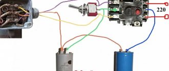
The use of conductors as a current limiter allows one to significantly reduce the dimensions of such a circuit. This is what the power supply for a 10-15 W diode lamp looks like.
What is a starter
Gas-discharge light sources have long been part of everyday life. They are used for lighting residential and industrial premises and provide stable lighting. It is quite stable when there is no degradation of elements in the circuit.
A typical circuit includes a lighting fixture, an inductor, and a trigger device. The choke is a regular inductor and is also involved in starting. But the main function is protection. The coil limits the voltage during a surge. It is the most durable element of the circuit.
The starter is needed only to start the circuit using gas-discharge lamps. Further, he does not take part in the operation of the lamp.
A fluorescent lamp (aka gas discharge or daylight) is a sealed bulb. It contains electrodes located on different sides. Its inner part is coated with phosphor - a substance that glows when electrons are emitted. The tube contains mercury vapor.
The standard gives the lamp 10 seconds to turn on from the moment voltage is applied.
Starter device for LL (fluorescent lamp)
The starting device is a necessary element of the lighting circuit for this type of light source. This is the second most important element of the illuminator.
A classic starter is a thing sensitive to operating conditions; it is the most short-lived component of the system. If it fails, the lighting system cannot be started.
Connection diagram of the starter to fluorescent lamps
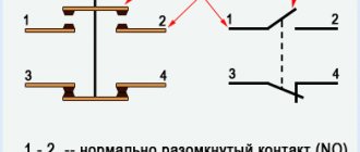
When examining the diagram, the functions performed by the starter become clear.
- Turns on when supply voltage is applied,
- At the moment of start, the cathodes are heated, since without their heating the emission of electrons is not possible.
- Opens the circuit after warming up.
The bimetallic starter circuit is always the same. There are various versions available.
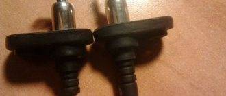
Starter appearance
The case is often made of plastic, the contacts are placed on a PCB plate (other dielectric material can also be used). Some manufacturers provide starters with a transparent viewing window. USSR-era starters had aluminum housings. There are only two elements inside: a bulb with bimetallic contacts and a capacitor. They are connected in parallel. The starter capacitor is required to smooth out high currents, extinguishes the arc discharge between the electrodes, and is also necessary to open the electrodes. The capacitor reduces wear on the starter. If there is no capacitor, then the electrodes can be soldered during an arc discharge between them. How long the scheme will work after that is unpredictable. A choke (inductor) is needed to create a pulse.
The flask contains two electrodes; it itself is filled with an inert gas. Neon is usually used, less often a hydrogen-helium mixture. Bimetallic electrodes, movable. Two designs have been developed: either two moving contacts (symmetrical) or one (unsymmetrical). The first one is more common. It is cheaper to produce. Old-style starters worked stably with a supply voltage variation within 20 percent. If the deviation from the nominal value is greater, work is not guaranteed. The new ones don't have this problem.
Starter operating principle
The components of the starting device are reviewed. How does he work?
- There is no voltage - the electrodes inside the bulb are open.
- Supply voltage is supplied. A glow discharge appears between the starter electrodes, the currents are small (usually no more than 50 mA).
- The glow discharge leads to heating of the electrodes. Under the influence of temperature, reversible deformation of the electrodes occurs. The discharge ends with the closure of these bimetallic electrodes.
- The circuit is closed, the electrodes begin to warm up to begin emission.
- The electrodes inside the starter bulb begin to cool and return to their original position. The chain breaks.
- This entire process resulted in a high voltage pulse passing through the inductor. The light turns on and the brightness reaches the standard level.
- The starter is connected in parallel with the light source. The voltage at its contacts is below rated. There is no longer a glow discharge; the bimetallic contacts inside the flask are not heated. It cannot work spontaneously. The required current is spent to ensure emission between the cathodes, this is necessary for the glow.
The principle of operation of circuits using a ballast capacitor
In this circuit, the condenser is a current filter. Voltage is supplied to the load only until the condenser is fully charged, the time of which depends on its capacity. In this case, no heat generation occurs, which removes restrictions on load power.
To understand how this circuit works and the principle of selecting a ballast element for an LED, let me remind you that voltage is the speed of electrons moving along the conductor, and current is the electron density.
For a diode, it is absolutely indifferent at what speed electrons will “fly” through it. The calculation of the conductor is based on the current limitation in the circuit. We can apply at least ten kilovolts, but if the current is several microamps, the number of electrons passing through the light-emitting crystal will be enough to excite only a tiny part of the light emitter and we will not see the glow.
At the same time, at a voltage of several volts and a current of tens of amperes, the electron flux density will significantly exceed the throughput of the diode matrix, converting the excess into thermal energy, and our LED element will simply evaporate in a cloud of smoke.
Connection diagram
The power of the light source must correlate with the parameters of the other components. If they do not match, then it is possible that either the circuit will not start at all, or the electrodes will be destroyed due to overheating when the startup starts.
To connect two LLs, circuit duplication is not required. It is advisable to reduce the number of elements. In this case, one of the chokes is released.
In the second diagram, additional gas-discharge lamps are connected in series, and the starters are connected in parallel. Otherwise the schemes are identical. The difference will be in the throttle rating. It must be designed for the total power of the lamps. The starter must match the lamp power. Typically, in a circuit with two lamps, the same power is used. A capacitor is desirable in parallel with the AC source. It is designed to improve nutritional parameters. With lamp powers of about 40 watts, a capacitance of 2 to 10 μF is usually sufficient. The capacitor voltage is selected not lower than twice the supply voltage.
How to calculate the capacitance of a smoothing capacitor?
To calculate the capacitance of the smoothing capacitor, you can use the approximate formula: C=3200*In/Un*Kp, Where In is the load current, Un is the load voltage, Kn is the ripple factor. For most types of equipment, the ripple coefficient is taken to be 0.01-0.001.
Interesting materials:
How should a bed be positioned in a children's room? How is the package delivered? How to call the Gazprombank operator? How to duplicate conditional formatting? How does melon affect the intestines? How does the swallow travel Krasnodar Sochi? How to eat chard? How is it flattering? What is Timur's last name from the book Timur and his team? How to farm gold in Warcraft?
Types of starters, their main parameters and markings.
Now there is a new type - electronic. This is already a new product. Structurally, they look exactly the same and are fully compatible with the “classics”. You can replace it without even thinking. Inside, instead of a capacitor and sealed bimetallic plates, there is an electronic circuit. It performs similar actions to starting a gas discharge lamp. There is no need to change the schema. The only disadvantage we can name is the price; it will be five times higher than the “classic”.
Starter design
Its advantages:
- The service life is much longer.
- When the components age, the starter will not work and the ballast device will not overheat.
- Wider temperature range.
- Built-in overcurrent protection.
- Electromagnetic interference is completely eliminated when starting the illuminator.
- Fixed heating time for the electrodes of the fluorescent lamp, therefore, increases the service life.
- The light source turns on immediately without flickering.
Now there are completely ready-made engineering solutions. These are the so-called electronic ballasts - electronic ballasts.
electronic ballasts
This type is a metal case that houses an electronic circuit; no additional elements are required. The input comes with supply voltage, the outputs are intended for connection to electrodes.
If necessary, it is easy to select a device for the required number of lamps. Installation and design are greatly simplified. The use of electronic ballasts significantly extends the service life due to “warm start”. The absence of moving bimetallic contacts ensures a silent start. The glow of the lamps will be even. Electronic ballasts provide stabilization of power parameters. Accordingly, the parameters of the electronic ballast and lamps must match.
This solution combines the advantages of electronic starters and the simplicity of the connection diagram. This is a completely turnkey solution. One device can be used for several lamps.
The downside is the price. Electronic components are more expensive than the combined price of the starter, capacitor and inductor. Conveniently, the connection diagram itself is usually depicted on the device itself, or in the instructions. Also, diagrams are always available on the websites of manufacturers.
The marking uniquely identifies the starter and is specified in GOST R IEC 60155-99 “Glow discharge starters for fluorescent lamps”.
Starter markings
Externally, starters for fluorescent lamps look like this:
Starter ST
Starter S2
Starter S10
A light bulb that lasts for over a century exists
Today, the average incandescent light bulb lasts about 1,500 hours, while top-of-the-line LED light bulbs ($25 each) last about 30,000 hours. Regardless of whether the century-old light bulb had a secret working formula or not, it burned for 113 years - that is, about 1 million hours. So why can't we create exactly the same long-lasting light bulb?
Lamp companies such as The Shelby Electric Company prided themselves on the long life of their products, so much so that the longevity of their products was a constant focus of their marketing campaigns. But by the mid-1920s, the way of doing business had changed somewhat and a new rule began to prevail:
“Products that don’t wear out are a tragedy for business.” This school of thought is called “planned obsolescence,” in which manufacturers deliberately shorten the lifespan of their products, resulting in them being replaced more quickly.
Before its dissolution during World War II, the cartel allegedly stopped all research aimed at creating longer-lasting light bulbs for twenty years.
As more efficient technologies (halogen, LED, compact fluorescent lamps, magnetic induction lamps) become available, the old incandescent lamps gradually become a relic of the past. But hanging from the white ceiling of Livermore Fire Station No. 6, the incredibly old light bulb is as relevant as ever and still refuses to fail.
Expert opinion
It-Technology, Electrical power and electronics specialist
Ask questions to the “Specialist for modernization of energy generation systems”
Driver At the input of the circuit there is a rectifying electrolyte capacitor, after which ripples with a frequency of 100 Hertz partially disappear. Ask, I'm in touch!
The light does not light, checking the starter is working properly.
Since everything has a finite service life, it happens that the lamp does not light up. "Who is guilty?". It’s definitely not a choke anymore; interturn short circuits are isolated cases. Lamp or starter?
Repairs are usually carried out at a modular level. Replace with a known good item. Repair at the component level is not practical.
If components are missing, the fault will have to be identified. It is advisable to look at all the wiring of the lamp, since if it does not work, it is not necessarily the starter or the lighting device itself that is to blame. The possibility of poor contact, for example in pads or connectors, cannot be ruled out.
If you decide to repair it yourself, be sure to follow the safety rules! Lighters use high voltage in their work. There is a risk of electrical injury! Do not touch live parts of the circuit under voltage.
You need to start by checking the voltage in the network. A reduction of more than 20 percent does not guarantee stable operation of older modifications of the starter for fluorescent lamps.
First you need to check the wiring. Using a tester, you need to measure the supply voltage. Let's assume that it exists and is normal. To clear your conscience, you can also measure the resistance of the inductor winding to see if there is a break or an interturn short circuit. This is a very rare case. Let's say this element is working. That leaves either the lamp or the starter.
First, let's open the starter, you need to inspect its insides. The first thing we do is inspect the integrity. The contacts in the bulb should not be in a solder joint; visually there should be a distance between them. The capacitor should not show signs of destruction. You can do it differently, connect the starter to an incandescent lamp with a power of 40 to 60 Watts (no more) and apply an alternating voltage of 220 Volts according to the diagram below.
Connection diagram of an incandescent lamp with a starter
If the filament does not light up or lights up constantly, without short-term shutdowns, then such a starter is considered inoperative. It is not economically feasible to repair it; the cost is not high. If the test circuit works, then the lighting fixture is most likely faulty.
It can also be checked. Since at some point the contacts of a working starter close, the gas-discharge lamp can be lit “manually”. A mechanical button without fixation is used instead of a trigger device. When power is supplied to such a circuit, when you press the button, the fluorescent lamp should light up, this will indicate a starter malfunction. If this does not happen, you will have to replace the gas discharge lamp. Cases of simultaneous failure of two elements are quite rare.
If an electronic ballast is used, then it is worth checking the lighting device itself. If the new one works and gives an even glow, then the old one must be replaced.
It is possible to repair the ballast. They are usually repairable. But this will require knowledge of electronics. Measuring equipment will be needed. Without the necessary qualifications, such repairs are impossible.
- Related Posts
- Quartz lamp for home disinfection
- Reasons for blinking tape
- Modern office lighting (ideas and recommendations)
Discussion: 2 comments
- Egor:
My friend and I tested a pack of starters using this method. I was electrocuted in the process. The starter, connected directly to 220, successfully detonated, leaving a message from the other world on the retina, burning the power wires and scalding the socket.PS, as a person who saw this lightning, I want to say that this should be repeated only in cases of complete idleness and lack of self-preservation instinct.
PPS is a cool spectacle, but the method works, we managed to test some of the starters.
Answer
Vampaza:
Hello, Egor. I'm glad everything worked out okay, electric current is no joke. For this method, it is best to use an incandescent lamp of no more than 40 W, make sure the wires are insulated and the circuit is assembled correctly. And, of course, first you should visually inspect the starter itself; do not connect a starter that has deformation, places of melting and burning.
Answer
A little about the basics of LED lamp circuitry
Judging by the comments, many people are interested not only in the parameters of LED lamps, but also in the theory of their internal structure. Therefore, I decided to talk a little about the basics of circuit solutions most often used in this area.
So, the core and main component of an LED light bulb is the LED. From the point of view of circuit design, light-emitting diodes are no different from any others, except that in the sense of using them as diodes themselves, they have terrible parameters - a very small permissible reverse voltage, a relatively large junction capacitance, a huge operating voltage drop (about 3.5 V for white LEDs - for example, for a rectifier diode it would be a nightmare), etc.
However, we understand that the main value of LEDs for humanity is that they glow, and sometimes quite brightly.
For an LED to glow happily ever after, it needs two conditions: a stable current through it and good heat dissipation from it. The quality of heat removal is ensured by various design methods, so now we will not dwell on this issue. Let's talk about why and how modern humanity achieves the first goal - stable current. By the way, about white LEDs
It is clear that white LEDs are most interesting for lighting. They are made on the basis of a crystal emitting blue light, filled with a phosphor that re-emit some of the energy in the yellow-green region. In the title picture you can clearly see that the current-carrying wires go into something yellow - this is the phosphor; the crystal is located underneath. In a typical spectrum of a white LED, a blue peak is clearly visible:
Spectra of LEDs with different color temperatures: 5000K (blue), 3700K (green), 2600K (red). More details here.
We have already figured out that in a circuitry sense, an LED differs from any other diode only in the parameter values. Here it must be said that the device is fundamentally nonlinear; that is, it does not obey Ohm’s law, which is familiar from school. The dependence of the current on the applied voltage on such devices is described by the so-called. current-voltage characteristic (volt-ampere characteristic), and for a diode it is exponential in nature. It follows from this that the slightest change in the applied voltage leads to a huge change in current, but that’s not all - with a change in temperature (as well as aging), the current-voltage characteristic shifts. In addition, the position of the I-V characteristic is slightly different for different diodes. I will stipulate separately - not only for each type, but for each copy, even from the same batch. For this reason, the distribution of current through diodes connected in parallel will necessarily be uneven, which cannot have a good effect on the durability of the structure. When making matrices, they try to either use series connection, which solves the problem fundamentally, or choose diodes with approximately the same forward voltage drop. To make the task easier, manufacturers usually indicate the so-called “bin” - a sampling code by parameters (including voltage) into which a specific instance falls.
CVC of a white LED.
Accordingly, for everything to work well, the LED must be connected to a device that, regardless of external factors, will automatically select with high accuracy the voltage at which a given current flows in the circuit (for example, 350 mA for one-watt LEDs), and monitor the process continuously. In general, such a device is called a current source, but in the case of LEDs these days it is fashionable to use the foreign word “driver”. In general, a driver is often called a solution that is primarily designed to work in a specific application - for example, a “MOSFET driver” is a chip designed to control specifically powerful field-effect transistors, a “seven-segment indicator driver” is a solution for specifically controlling seven-segment devices, etc. . That is, by calling a current source an LED driver, people are hinting that this current source is designed specifically to work with LEDs. For example, it may have specific functions - something like the presence of a DMX-512 light interface, detection of open circuits and short circuits at the output (and a regular current source, in general, should work without problems on a short circuit), etc. However, the concepts are often confused, and, for example, the most common adapter (voltage source!) for LED strips is called a driver.
In addition, devices designed to set the mode of a lighting device are often called ballast.
So, current sources. The simplest current source can be a resistor connected in series with the LED. This is done at low powers (up to half a watt), for example, in the same LED strips. With increasing power, the losses on the resistor become too large, and the requirements for current stability increase, and therefore the need arises for more advanced devices, the poetic image of which I drew above. All of them are built according to the same ideology - they have a regulatory element controlled by current feedback.
Current stabilizers are divided into two types - linear and pulsed. Linear circuits are relatives of the resistor (the resistor itself and its analogues also belong to this class). They usually do not provide any particular gain in efficiency, but they do improve the quality of current stabilization. Pulse circuits are the best solution, but they are more complex and expensive.
Let's now take a quick look at what you might see in or around LED bulbs these days.
Capacitor ballast
Capacitor ballast is a development of the idea of connecting a resistor in series with an LED. In principle, an LED can be connected to a socket like this:
A counter-connected diode is necessary in order to prevent breakdown of the LED at the moment when the mains voltage changes polarity - I have already mentioned that there are no LEDs with a permissible reverse voltage of hundreds of volts. In principle, instead of a reverse diode, you can install another LED.
The resistor value in the circuit above is designed for an LED current of about 10 - 15 mA. Since the mains voltage is much greater than the drop across the diodes, the latter can be ignored and calculated directly according to Ohm’s law: 220/20000 ~ 11 mA. You can substitute the peak value (311 V) and make sure that even in the extreme case the diode current does not exceed 20 mA. Everything works out great, except that the resistor will dissipate about 2.5 W of power, and the LED will dissipate about 40 mW. Thus, the efficiency of the system is about 1.5% (in the case of one LED it will be even less).
The idea of the method under consideration is to replace the resistor with a capacitor, because it is known that in alternating current circuits reactive elements have the ability to limit current. By the way, you can also use a choke; moreover, this is done in classic electromagnetic ballasts for fluorescent lamps.
Calculating using the formula from the textbook, it is easy to find that in our case we need a capacitor with a capacity of 0.2 μF, or an inductance coil of about 60 H. Here it becomes clear why chokes are never found in such ballasts of LED lamps - a coil of such inductance is a serious and expensive structure, but a 0.2 µF capacitor is much easier to obtain. Of course, it must be designed for peak mains voltage, and preferably with a margin. In practice, capacitors with an operating voltage of at least 400 V are used. Having slightly supplemented the circuit, we get what we have already seen in the previous article.
Lyrical digression
“Microfarad” will be abbreviated as “μF”.
I dwell on this because quite often I see people writing “mF” in this context, while the latter is an abbreviation for “millifarad”, that is, 1000 µF. In English, “microfarad”, again, is not written as “mkF”, but, on the contrary, “uF”. This is because the letter "u" resembles the letter "μ" with the tail torn off. So, 1 F/F = 1000 mF/mF = 1000000 μF/uF/μF
, and nothing else!
In addition, “Farad” is masculine, as it is named after a great male physicist. So, “four microfarads”, but not “four microfarads”!
As I already said, such ballast has only one advantage - simplicity and low cost. Like a ballast with a resistor, it does not provide very good current stabilization, and, even worse, there is a significant reactive component, which is not particularly good for the network (especially at noticeable powers). In addition, as the desired current increases, the required capacitance of the capacitor will increase. For example, if we want to turn on a one-watt LED operating at a current of 350 mA, we will need a capacitor with a capacity of about 5 μF, designed for a voltage of 400 V. This is already more expensive, larger in size and more complex in design. Suppression of ripples is also not easy here. In general, we can say that capacitor ballast is forgivable only for small beacon lamps, nothing more.
Transformerless step-down topology
This circuit solution belongs to the family of transformerless converters, which includes step-down, step-up and inverting topologies. In addition, transformerless converters also include SEPIC, Chuka converter and other exotics, such as switched capacitors. In principle, an LED driver can be built on the basis of any of them, but in practice they are much less common in this capacity (although the boost topology is used, for example, in many flashlights).
One driver option based on a transformerless step-down topology is shown in the figure below.
In nature, such a connection can be observed in the example of the ZXLD1474 or the ZXSC310 connection option (which, by the way, is just a boost converter in the original connection circuit).
Here the LED is connected in series with the coil. The control circuit monitors the current using sense resistor R1 and controls switch T1. If the current through the LED drops below a predetermined minimum, the transistor opens and the coil with the LED connected in series with it is connected to the power source. The current in the coil begins to increase linearly (red section on the graph), diode D1 is locked at this time. As soon as the control circuit registers that the current reaches the specified maximum, the switch closes. According to the first law of commutation, the coil strives to maintain current in the circuit due to the energy accumulated in the magnetic field. At this moment, current flows through diode D1. The energy of the coil field is consumed, the current strength decreases linearly (green section on the graph). When the current drops below a predetermined minimum, the control circuit detects this and opens the transistor again, pumping energy into the system - the process repeats. Thus, the current is maintained within specified limits.
A distinctive feature of the step-down topology is the ability to make the pulsations of the light flux as small as desired, since in such a connection the current through the LED is never interrupted. The path to approaching the ideal lies through increasing the inductance and increasing the switching frequency (today there are converters with operating frequencies of up to several megahertz).
Based on this topology, the Gauss lamp driver discussed in the previous article was made.
The disadvantage of the method is the lack of galvanic isolation - when the transistor is open, the circuit is directly connected to the voltage source, in the case of network LED lamps - to the network, which can be unsafe.
Flyback converter
Although a flyback converter contains something similar to a transformer, in this case the part is more accurately called a two-winding inductor, since current never flows through both windings at the same time. In fact, the operating principle of a flyback converter is similar to transformerless topologies. When T1 is open, the current in the primary winding increases, energy is stored in the magnetic field; in this case, the switching polarity of the secondary winding is deliberately selected so that diode D3 is closed at this stage and no current flows on the secondary side. The load current at this moment is supported by capacitor C1. When T1 closes, the polarity of the voltage on the secondary winding is reversed (since the derivative of the current in the primary winding changes sign), D3 opens and the stored energy is transferred to the secondary side. In terms of current stabilization, everything is the same - the control circuit analyzes the voltage drop across resistor R1 and adjusts the timing
e parameters so that the current through the LEDs remains constant. Most often, a flyback converter is used at powers of no more than 50 W; then it ceases to be advisable due to increasing losses and the required dimensions of the transformer-choke.
It must be said that there are options for flyback drivers without an opto-isolator (for example). They rely on the fact that the primary and secondary winding currents are coupled, and with certain reservations it is possible to limit the analysis to the current of the primary winding (or, more often, a separate auxiliary winding) - this allows saving on parts and, accordingly, a cheaper solution.
The flyback converter is good because, firstly, it ensures isolation of the secondary part from the network (higher safety), and, secondly, it makes it relatively easy and cheap to produce lamps compatible with standard dimmers for incandescent lamps, as well as to arrange coefficient correction power.
Lyrical digression
The flyback converter is so called because initially a similar method was used to produce high voltage in televisions based on cathode ray tubes.
The high voltage source was circuitously combined with a horizontal scanning circuit, and a high voltage pulse was obtained during the return stroke
of the electron beam.
A little about ripples
As already mentioned, pulsed sources operate at fairly high frequencies (in practice, from 30 kHz, more often around 100 kHz). Therefore, it is clear that a serviceable driver itself cannot be a source of a large ripple factor - primarily because at frequencies above 300 Hz this parameter is simply not standardized, and, besides, high-frequency ripples are in any case quite easy to filter out. The problem is the mains voltage.
The fact is that, of course, all of the above circuits (except for the circuit with a quenching capacitor) operate on constant voltage. Therefore, at the input of any electronic ballast, first of all, there is a rectifier and a storage capacitor. The purpose of the latter is to power the ballast at those moments when the mains voltage drops below the operating threshold of the circuit. And here, alas, a compromise is necessary - high-voltage electrolytic capacitors of large capacity, firstly, cost money, and, secondly, they take up precious space in the lamp body. This is also where the root cause of power factor problems lies. The described circuit with a rectifier has uneven current consumption. This leads to the emergence of higher harmonics, which is the reason for the deterioration of the parameter of interest to us. Moreover, the better we try to filter the voltage at the ballast input, the lower the power factor we will get, unless we make special efforts. This explains the fact that almost all lamps with a low ripple factor that we have seen show a very mediocre power factor, and vice versa (of course, the introduction of an active power factor corrector will affect the price, so for now they prefer to save on it).
Perhaps this is all that, as a first approximation, can be said on the topic of electronics of LED lamps. I hope that with this article I have to some extent answered all the circuit-related questions that were asked to me in the comments and personal messages.