Is it possible to control engine speed with a dimmer?
To regulate the rotation speed of single-phase electric motors with a supply voltage of 220 V, triac rotation speed controllers are used. The dimmer (triac dimmer), in turn, is designed to control a resistive load and should be used only as a regulator of lamp brightness.
Interesting materials:
How to make a big clock on the lock screen? How to make a big clock on a computer? How to make a large hole in thick metal? How to make a large parenthesis in Word? How to make a Wither boss? How to make a bot an admin in a conversation? How to make a bracelet on a fishing line? How to make it the default browser? How to make a doghouse for a German Shepherd with your own hands? How to make a booklet for a project in Word?
Changing the speed of an IM with a squirrel-cage rotor
There are several ways:
- Rotation control by changing the electromagnetic field of the stator: frequency regulation and changing the number of pole pairs.
- Changing the slip of the electric motor by decreasing or increasing the voltage (can be used for IMs with a wound rotor).
Frequency regulation
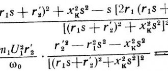
In this case, the adjustment is made using a frequency conversion device connected to the engine. For this purpose, powerful thyristor converters are used. The process of frequency regulation can be considered using the example of the EMF formula of a transformer:
U1=4.44w1k1fΦ
This expression means that in order to maintain a constant magnetic flux, which means maintaining the overload capacity of the electric motor, the supply voltage level should be adjusted simultaneously with frequency conversion. If the expression calculated by the formula is saved:
U1/f1=U'1/f'1
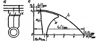
then this means that the critical moment has not been changed. And the mechanical characteristics correspond to the figure below; if you do not understand what these characteristics mean, then in this case the adjustment occurs without loss of power and torque.
The advantages of this method are:
- smooth regulation;
- changing the rotor speed up and down;
- rigid mechanical characteristics;
- efficiency.
There is only one drawback - the need for a frequency converter, i.e. increase in the cost of the mechanism. By the way, on the modern market there are models with single-phase and three-phase input, the cost of which with a power of 2-3 kW is in the range of 100-150 dollars, which is not too expensive for full adjustment of the drive of machine tools in a private workshop.
Switching the number of pole pairs
This method is used for multi-speed motors with complex windings that allow you to change the number of pairs of its poles. The most widely used are two-speed, three-speed and four-speed IMs. The adjustment principle is easiest to consider on the basis of a two-speed IM. In such a machine, the winding of each phase consists of two half-windings. The rotation speed changes when connecting them in series or parallel.
In a four-speed electric motor, the winding is made in the form of two parts independent from each other. When the number of pole pairs of the first winding changes, the speed of the electric motor changes from 3000 to 1500 rpm. Using the second winding, rotation is adjusted at 1000 and 500 rpm.
When the number of pole pairs changes, the critical moment also changes. To keep it unchanged, it is necessary to simultaneously regulate the supply voltage while changing the number of pole pairs, for example, by switching the star-delta circuit and their variations.
Advantages of this method:
- rigid mechanical characteristics of the engine;
- high efficiency.
Flaws:
- step adjustment;
- large weight and overall dimensions;
- high cost of the electric motor.
From the network
Single-phase AC motors also allow you to control the rotation of the rotor.
Collector machines
Such motors are found on electric drills, jigsaws and other tools. To reduce or increase the speed, it is enough, as in previous cases, to change the supply voltage. There are also solutions for this purpose.
The structure connects directly to the network. The adjusting element is a triac, which is controlled by a dinistor. The triac is placed on the heat sink, the maximum load power is 600 W.
If there is a suitable LATR, you can do all this using it.
Two phase motor
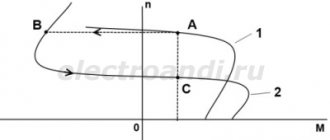
The device, which has two windings - starting and working, is two-phase in principle. Unlike three-phase, it has the ability to change the rotor speed. The characteristic of its rotating magnetic field is not circular, but elliptical, which is due to its design.
Read also: How to solder metal to metal with a soldering iron
There are two possibilities for controlling the speed:
- Change the amplitude of the supply voltage (Uy);
- Phase - change the capacitance of the capacitor.
Such units are widely used in everyday life and in production.
Regular asynchronous
Three-phase electric machines, despite their ease of operation, have a number of characteristics that need to be taken into account. If you simply change the supply voltage, the torque will change within a small range, but no more. In order to regulate speed within a wide range, you need quite complex equipment, which is difficult and expensive to simply assemble and set up.
For this purpose, the industry has launched the production of frequency converters that help change the speed of the electric motor in the desired range.
The asynchronous machine gains momentum in accordance with the parameters set on the frequency driver, which can be changed in a wide range. The converter is the best solution for such engines.
How is a motor indicated on electrical diagrams?
The electric motor is indicated in the diagrams using the letter “M” inscribed in a circle. The diagrams may also indicate the serial number of the motor, the number of phases (1 or 3), the type of current (AC or DC), the method of connecting the windings (star or delta), and power. Examples of notation are shown below.
How to increase the power of an electric motor?
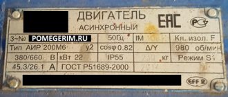
The rated shaft power, which is indicated on the motor nameplate, is usually limited by the permissible current, and therefore by the heating of the drive housing. Therefore, when increasing power, it is necessary to take additional measures to cool the electric motor by installing a separate fan.
When using a frequency converter to increase power, you can change the PWM carrier frequency, but you should avoid overheating the inverter. Power can also be increased using a gearbox or belt drive, sacrificing the number of revolutions, if this is acceptable.
If the above tips are not applicable, you will have to change the engine to a more powerful one.
Typical electric motor faults
There are two types of electric motor faults: electrical and mechanical.
Electrical faults include winding-related faults:
- turn-to-turn short circuit
- short circuit of the winding to the housing
- winding break
To eliminate these faults, the motor must be rewinded.
- wear and friction in bearings
- turning the rotor on the shaft
- engine housing damage
- rotation or damage to the blower impeller
Bearings should be replaced regularly, taking into account their wear and service life. The impeller is also replaced if damaged. The remaining faults are practically impossible to eliminate, and the only solution is to replace the engine.
If you have questions that are not answered in this article, please write to us. We'll be happy to help!
What is an asynchronous motor?
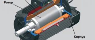
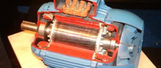
AC electric motors have found quite wide application in various spheres of our life, in hoisting, processing, and measuring equipment. They are used to convert electrical energy that comes from the network into mechanical energy of a rotating shaft. Most often, asynchronous AC converters are used. In them, the rotation speed of the rotor and stator is different. A structural air gap is provided between these active elements.
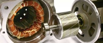
Both the stator and the rotor have a rigid core made of electrical steel (composited type, made of plates), acting as a magnetic circuit, as well as a winding that fits into the structural grooves of the core. It is the way in which the rotor winding is organized or laid out that is the key criterion for classifying these machines.
Squirrel-cage motors (SCR)
Here, a winding is used in the form of aluminum, copper or brass rods, which are inserted into the grooves of the core and closed on both sides by disks (rings). The type of connection of these elements depends on the engine power: for small values, the method of joint casting of disks and rods is used, and for large values, separate production is used, followed by welding to each other. The stator winding is connected using delta or star circuits.
Wound rotor motors
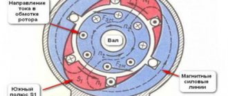
The three-phase rotor winding is connected to the network via slip rings on the main shaft and brushes. The “star” scheme is taken as the basis. The figure below shows a typical design of such an engine.
Read also: Types of cast iron, their use and labeling
System design
The commutator type motor consists mainly of a rotor, a stator, as well as brushes and a tachogenerator.
- The rotor is part of the rotation, the stator is an external type of magnet.
- Brushes, which are made of graphite, are the main part of the sliding contact, through which voltage is applied to the rotating armature.
- A tachogenerator is a device that monitors the rotation characteristics of a device. If there is a violation in the regularity of the rotation process, then it adjusts the voltage level entering the engine, thereby making it smoother and slower.
- Stator. Such a part may include not one magnet, but, for example, two pairs of poles. At the same time, instead of static magnets, there will be coils of electromagnets. Such a device is capable of performing work both from direct current and alternating current.
Scheme of the speed controller of the commutator motor
Special frequency converters are used in the form of speed controllers for 220 V and 380 V electric motors . Such devices are considered high-tech , and they help to radically transform the current characteristics (signal shape, as well as frequency). They are equipped with powerful semiconductor transistors, as well as a pulse-width modulator. The entire process of operating the device occurs through the control of a special unit on a microcontroller. The change in speed in the rotation of the motor rotor occurs quite slowly.
It is for this reason that frequency converters are used in loaded devices. The slower the acceleration process occurs, the less load will be placed on the gearbox, as well as the conveyor. In all frequency generators you can find several degrees of protection: by load, current, voltage and other indicators.
Some models of frequency converters supply power from a single-phase voltage (it will reach 220 Volts) and create a three-phase voltage from it. This helps to connect an asynchronous motor at home without the use of particularly complex circuits and designs. In this case, the consumer will not lose power while working with such a device.
Why use such a device-regulator?
If we talk about regulator motors , then the required speed is:
- For significant energy savings. So, not every mechanism needs a lot of energy to perform the work of rotating the motor; in some cases, rotation can be reduced by 20-30 percent, which will help significantly reduce energy costs by several times.
- For the protection of all mechanisms, as well as electronic types of circuits. Using the converter frequency, you can exercise certain control over the overall temperature, pressure, as well as other indicators of the device. In the case when the engine operates as a specific pump, then a specific pressure sensor should be inserted into the container into which air or liquid is pumped. When the maximum mark is reached, the motor will simply automatically stop working.
- For the soft start process. There is no particular need to use additional electronic equipment - everything can be done by changing the settings of the frequency converter.
- To reduce device maintenance costs. With the help of such speed controllers in 220 V engines, the possibility of failure of devices, as well as certain types of mechanisms, can be significantly reduced.
The circuits used to create frequency converters in an electric motor are widely used in most household devices. Such a system can be found in wireless power supplies, welding machines, phone chargers, power supplies for personal computers and laptops, voltage stabilizers, lamp ignition units for backlighting modern monitors, as well as LCD TVs.
220V electric motor speed controller
You can make it completely independently , but to do this you will need to study all the possible technical features of the device. By design, several types of main parts can be distinguished. Namely:
- The electric motor itself.
- Microcontroller control system for the conversion unit.
- Drive and mechanical parts that are associated with the operation of the system.
Just before starting the device, after applying a certain voltage to the windings, the process of rotating the engine begins with maximum power. It is this feature that will distinguish asynchronous devices from other types. On top of everything else, the load from the mechanisms that set the device in motion is added. Ultimately, at the initial stage of operation of the device, the power, as well as the current consumption, only increases to the maximum level.
At this time, the process of releasing the greatest amount of heat occurs. Overheating occurs in the windings, as well as in the wires. Using partial conversion will help prevent this from happening. If you install a soft start, then to the maximum speed mark (which can also be adjusted by equipment and may not be 1500 rpm, but only 1000), the engine will begin to accelerate not at the first moment of operation, but over the next 10 seconds (at the same time, every second the device will add 100-150 revolutions). At this time, the load on all mechanisms and wires begins to decrease several times.
How to make a regulator with your own hands
You can completely independently create an electric motor speed controller of about 12 V. To do this, you should use a switch of several positions at once , as well as a special wirewound resistor. With the help of the latter, the supply voltage level changes (and at the same time the rotation speed indicator). The same systems can be used to perform asynchronous movements, but they will be less effective.
Many years ago, mechanical regulators were widely used - they were built on the basis of gear drives or their variators. But such devices were considered not very reliable. Electronic means showed themselves several times better, since they were not so large and allowed for finer adjustment of the drive.
In order to create an electric motor rotation controller, it is worth using several devices at once, which can either be bought at any hardware store or removed from old inventory devices. To complete the adjustment process, it is worth including a special variable resistor circuit . With its help, the process of changing the amplitude of the signal entering the resistor occurs.
Implementation of a management system
To significantly improve the performance of even the simplest equipment, it is worth connecting microcontroller control to the engine speed controller circuit. To do this, you should choose a processor that has a suitable number of inputs and outputs, respectively: to connect sensors, buttons, and special electronic keys.
To carry out experiments, it is worth using a special microcontroller AtMega 128 - this is the easiest to use and widely used controller. In free use you can find a large number of schemes using it. In order for the device to perform the correct operation, it is worth recording a certain algorithm of actions - responses to certain movements. For example, when the temperature reaches 60 degrees Celsius (the measurement will be noted on the graph of the device itself), the device should automatically turn off.

