Transformer manufacturing
Since we have a ring, most likely its edges will be at an angle of 90 degrees, and if the wire is wound directly onto the ring, the varnish insulation may be damaged, and as a result, an interturn short circuit and the like. In order to eliminate this point, the edges can be carefully cut with a file, or wrapped with cotton tape. After this, you can wind the primary.
After we have wound it, we again wrap the ring with the primary winding with electrical tape.
How to etch a board
Place the prepared and dried board in a ferric chloride solution. Its saturation should be such that the copper is corroded as quickly as possible. If the process is slow, it is recommended to increase the concentration of ferric chloride in the water. If this does not help, then try heating the solution. To do this, fill a container with water, place a jar of solution in it (do not forget that it is advisable to store it in a plastic or glass container) and heat over low heat. Warm water will heat the ferric chloride solution.
If you have a lot of time or do not have ferric chloride, then use a mixture of salt and copper sulfate. The board is prepared in a similar way and then placed in the solution. The disadvantage of this method is that the power supply board is etched very slowly; it will take almost a day for all copper to completely disappear from the surface of the PCB. But for lack of a better one, you can use this option.
Input filter capacitance and voltage ripple
In the input filters of electronic ballasts, to save space, small capacitors are used, on which the magnitude of voltage ripple with a frequency of 100 Hz depends.
To reduce the level of voltage ripple at the power supply output, you need to increase the capacitance of the input filter capacitor. It is advisable that for every watt of PSU power there is one microfarad or so. An increase in capacitance C0 will entail an increase in the peak current flowing through the rectifier diodes at the moment the power supply is turned on. To limit this current, a resistor R0 is needed. But, the power of the original CFL resistor is small for such currents and it should be replaced with a more powerful one.
If you need to build a compact power supply, you can use electrolytic capacitors, which are used in film flash lamps. For example, Kodak disposable cameras have miniature capacitors without identification marks, but their capacity is as much as 100µF at a voltage of 350 Volts.
Introduction.
Compact Fluorescent Lamps (CFLs) are now widely used. To reduce the size of the ballast choke, they use a high-frequency voltage converter circuit, which can significantly reduce the size of the choke.
If the electronic ballast fails, it can be easily repaired. But when the bulb itself fails, the light bulb is usually thrown away.
However, the electronic ballast of such a light bulb is an almost ready-made switching power supply unit (PSU). The only way the electronic ballast circuit differs from a real switching power supply is the absence of an isolation transformer and a rectifier, if necessary.
At the same time, modern radio amateurs experience great difficulty in finding power transformers to power their homemade products. Even if a transformer is found, its rewinding requires the use of a large amount of copper wire, and the weight and dimensions of products assembled on the basis of power transformers are not encouraging. But in the vast majority of cases, the power transformer can be replaced with a switching power supply. If you use ballast from faulty CFLs for these purposes, the savings will amount to a significant amount, especially if we are talking about transformers of 100 watts or more.
Return to top menu
Filter
The output voltage must be filtered - it contains a large number of conversion products. Since the inverter operates at a fairly high frequency, filters containing not only capacitors, but also small-sized chokes with relatively low inductance become effective.
L- and U-shaped LC filters.
To calculate the filter elements, it is necessary to specify the pulsation coefficient Kp. It is selected from the expected load:
- sensitive equipment for radio reception, preliminary stages of audio equipment, microphone amplifiers - Kp = 10-5..10-4 ;
- audio frequency amplifiers – Кп=10-4..10-3 ;
- middle and low class receiving and sound reproducing equipment – Kp=10-2..10-3 .
For an L-shaped filter installed after a full-wave rectifier, the following relations apply:
- L*C=25000/(f2+Kp);
- L/C=1000/R2н.
In these formulas:
- L – inductance of the inductor in µH;
- C is the capacitance of the capacitor in microfarads;
- f – conversion frequency in Hz;
- Rн – load resistance in Ohms.
For U-shaped filter:
- С1=С2=С;
- L/C=1176/R2н.
The dimension of the values is the same as for the previous filter.
Rectifier.
All secondary rectifiers of a half-bridge switching power supply must be full-wave. If this condition is not met, the magnetic pipeline may become saturated.
There are two widely used full-wave rectifier designs.
1. Bridge circuit.
2. Circuit with zero point.
The bridge circuit saves a meter of wire, but dissipates twice as much energy on the diodes.
The zero-point circuit is more economical, but requires two perfectly symmetrical secondary windings. Asymmetry in the number of turns or location can lead to saturation of the magnetic circuit.
However, it is precisely zero-point circuits that are used when it is necessary to obtain high currents at a low output voltage. Then, to further minimize losses, instead of conventional silicon diodes, Schottky diodes are used, on which the voltage drop is two to three times less.
Example.
Computer power supply rectifiers are designed according to a zero-point circuit. With a power delivered to the load of 100 Watts and a voltage of 5 Volts, even Schottky diodes can dissipate 8 Watts.
100 / 5 * 0,4 = 8(Watt)
If you use a bridge rectifier, and even ordinary diodes, then the power dissipated by the diodes can reach 32 Watts or even more.
100 / 5 * 0,8 * 2 = 32(Watt).
Pay attention to this when you design a power supply so that you don’t have to look for where half the power disappeared. 
In low-voltage rectifiers it is better to use a circuit with a zero point. Moreover, with manual winding, you can simply wind the winding in two wires. In addition, high-power pulse diodes are not cheap.
Return to top menu
The difference between a CFL circuit and a pulse power supply
This is one of the most common electrical circuits for energy-saving lamps. To convert a CFL circuit into a switching power supply, it is enough to install just one jumper between points A - A' and add a pulse transformer with a rectifier. Elements that can be deleted are marked in red.
And this is a complete circuit of a switching power supply, assembled on the basis of a CFL using an additional pulse transformer.
To simplify, the fluorescent lamp and several parts were removed and replaced with a jumper.
As you can see, the CFL circuit does not require major changes. Additional elements introduced into the scheme are marked in red.
Return to top menu
How to assemble: step by step instructions
For those who want to assemble a switching power supply with their own hands, here are several assembly diagrams.
The simplest version of a low-power switching power supply
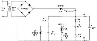
Let's consider the circuit of a switching power supply with a power of up to 2 W. The rectifier and filter in it are assembled on resistor R1 (from 25 to 50 Ohms), diode VD1 and capacitor C1 (20.0 μF, 400 V). The high-frequency converter is a self-oscillator assembled on transistor VT1, transformer TR1, frequency-setting circuit resistor R2 (470 kOhm) and capacitor C2 (3300 pF, 1000 V). The voltage removed from the output winding of the transformer is rectified by diode VD2 and smoothed by electrolytic capacitor C3 (47 pF, 50 V).
Any transformer from a non-working transformer used in charging a mobile phone or other low-power power source will be suitable as a core for a transformer. Winding occurs in the following order:
- first we wind 200 turns of the primary winding with copper wire with a cross section of 0.08-0.1 mm;
- we isolate the primary winding and wind 5 turns of the base winding with the same wire;
- We wind the secondary winding. Wire diameter – 0.4 mm. The number of turns depends on what voltage you need to get at the output at the rate of one turn per volt.
Expert opinion
Alexey Bartosh
Specialist in repair and maintenance of electrical equipment and industrial electronics.
Ask a Question
Attention! There should be a small non-magnetic gap between the halves of the magnetic core. Usually it is already present on cores taken from smartphone charger transformers. If there is none, place a layer of paper between the core halves.
We tighten the finished transformer with electrical tape or tape.
Single-ended, flyback switching power supply
Let's consider a single-cycle power supply made using a self-excited self-oscillator circuit. Output voltage – 16 V, device power – 15 W.
At the input of the device, the alternating voltage of the electrical network is rectified using a diode bridge assembled on diodes D1-D4 (you can use any diodes rated for a voltage of 400 V and a current of 0.5 A, for example, N4007). Capacitor C1 (20 µF, 400 V) is responsible for smoothing out ripples. To prevent current surge when turned on, resistor R1 (25-50 Ohms) is used.
The initial bias based on transistor T1 (you can use 13003 or 13005) is set by resistor R2 (470 kOhm) and diode D6 (N4007). To smooth out voltage surges that occur when T1 is closed, the circuit includes elements such as: capacitor C2 (3300 pF 1000 V), diode D5 (N4007) and resistor R3 (30 kOhm 1 W, or you can use two 15 kOhm resistors).
The positive feedback pulses necessary to maintain the self-oscillation mode are supplied to the base T1 through resistor R4 (150 Ohm) and capacitor C3 (47 pF, 50 V). A chain consisting of T2, R5 (1.5 kOhm), D9 (zener diode KS515) is needed to stabilize the voltage.
The high-frequency converter is assembled using a flyback circuit. When T1 is open, energy is accumulated on the transformer, while diode D7 (KD213 is used in conjunction with a radiator with an area of 10 cm2) is in the closed state. After transistor T1 closes, the stored magnetic energy is released, diode D7 opens, current appears in the secondary circuit, capacitor C6 (100.0 μF, 25 V) is charged. Capacitors C4 (2200 pF) and C5 (0.1 µF) are needed to reduce interference.
Stabilization of the output voltage occurs according to the scheme described below. When the device is connected to the network, the generator starts. Voltage appears on the secondary winding. Capacitor C6 (100.0 µF, 25 V) is charging. When the voltage across it exceeds 16.3 V, the zener diode D9 (KS515) opens. Transistor T2 (KT603) opens and short-circuits the emitter junction T1. Transistor T1 closes, the generator stops working, and capacitor C6 begins to discharge. When the voltage at C6 becomes less than 16.3 volts, the zener diode D9 closes and closes T2. Thanks to this, T1 opens and generator operation resumes.
The primary winding w1 of the transformer is wound with 0.25 mm wire and has 179 turns. The base winding w2 contains two turns wound with the same wire. The secondary winding w2 consists of 14 turns of wire 0.6-0.7 mm.
You can take any low-power light bulbs, designed for a voltage from 24 to 36 V and a current from 100 to 200 mA.
Powerful switching power supply
Consider a switching power supply with an output power of 300 W.
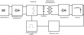
The generator in this design is the TL494 integrated circuit. Control signals from the output of this IC are supplied alternately to MOS (MOSFET) transistors VT1 and VT2 (IRFZ34). Pulses from these transistors through a transformer and pulse shaper come to powerful transistors VT3 and VT4 (IRFP460). The converter is made using powerful transistors VT3 and VT4 in a half-bridge circuit.
All four windings of transformer TR1 are wound with 0.5 mm wire and contain 50 turns. In the TR2 transformer, the first winding consists of 110 turns of wire with a diameter of 0.8 mm. The number of turns of winding number two depends on the desired output voltage, at the rate of one turn per two volts. Winding three is wound with 12 turns of wire with a diameter of 0.8 mm.
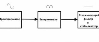
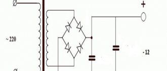
Mains voltage rectifier: the most popular design
Rule No. 3: after the output from the filter, the voltage is supplied to the rectifier circuit , which in the basic version consists of a diode bridge and an electrolytic capacitor.
During the electrical conversion, the shape of a sine wave, consisting of half-waves of opposite signs, first changes to a signal in a positive direction after the diode assembly, and then these pulsations are smoothed out to an almost constant amplitude value of 311 volts.
Such a network voltage rectifier is included in the operation of all power supplies.
Why do you need a diode bridge?
As we should have understood, a diode bridge is needed in order to convert alternating current into direct current. This device was invented by the German scientist Leots Graetz; the second name for the diode bridge is the Graetz bridge circuit.
The operating principle is as follows: an alternating electric current is supplied to the input of the diode bridge, and a constant pulsating current appears at its outputs. The ripple frequency depends on the frequency of the alternating current.
If we take the standard frequency value for our latitudes (50 Hz), then the DC ripple frequency will be equal to 100 Hz. In order to smooth out the ripples, a capacitor is installed - this device will be a full-fledged rectifier.
The circuit discussed in this article is used in a two-phase network. For a three-phase network, other schemes are used that will not be discussed in this article. It is made in the form of four connected diodes or a diode assembly. A diode assembly is the same diode bridge, only made in one housing. Both options have their pros and cons. For example, if one of the diodes malfunctions, having to replace the entire diode assembly is its disadvantage.
When selecting a diode bridge or individual diodes for it, the following characteristics are taken into account:
- Diode reverse voltage;
- Reverse current of diodes;
- Long-term permissible current;
- Maximum operating temperature;
- Operating frequency (relevant for high-frequency devices).
These are the main parameters by which diodes for self-assembly or diode bridges are selected. It all depends on the load you want to power, but whether it’s a power supply or a charger, it’s better to take it with a reserve rather than back to back.
This will keep your device safe. There are situations when the diode bridge can become very hot or even burn out. This occurs due to the high current passing through the diodes, which heats them up, or due to poor cooling, especially in powerful devices.
For better cooling and prevention of diode bridge combustion, it is recommended to use radiators that will effectively dissipate heat.
Diodes also have their own resistance and the voltage drops across each of them. For high-voltage devices this is not a significant loss, but for low-voltage receivers (up to 12 volts) such losses will be significant.
In this situation, instead of conventional diodes, Schottky diodes are used in the circuit. A rectifier made of such diodes will have a low voltage drop, acceptable for low-voltage equipment.
Due to the characteristics of Schottky diodes, such diode bridges can operate at ultra-high frequencies. But be careful, at the slightest excess of the reverse voltage, such diodes fail.
Examination
In order to correctly assemble the power supply, you need to be careful about installing the polar elements, and you should also be careful when working with mains voltage. After disconnecting the unit from the power source, there should be no dangerous voltage remaining in the circuit. If assembled correctly, no further adjustment is required.
You can check the correct operation of the power supply as follows:
- We connect it to the circuit, the output is a light bulb, for example, 12 Volts. At the first short-term start, the light should be on. In addition, you should pay attention to the fact that all elements should not heat up. If something gets hot, it means the circuit is assembled incorrectly.
- At the second start, we measure the current value using a tester. Let the unit operate for a sufficient amount of time to ensure that there are no heating elements.
Power supply 20 Watt.
A power supply with a power close to the power of the original CFL can be assembled without even winding a separate transformer. If the original inductor has enough free space in the magnetic circuit window, then you can wind a couple of dozen turns of wire and get, for example, a power supply for a charger or a small power amplifier.
The picture shows that one layer of insulated wire was wound over the existing winding. I used MGTF wire (stranded wire in fluoroplastic insulation). However, in this way you can get a power of only a few watts, since most of the window will be occupied by the wire insulation, and the cross-section of the copper itself will be small.
If more power is required, then ordinary varnished copper winding wire can be used.
Attention! The original inductor winding is under mains voltage! When making the modification described above, be sure to take care of reliable inter-winding insulation, especially if the secondary winding is wound with ordinary varnished winding wire. Even if the primary winding is covered with a synthetic protective film, an additional paper gasket is necessary!
As you can see, the winding of the inductor is covered with a synthetic film, although often the winding of these chokes is not protected by anything at all.
We wrap two layers of electrical cardboard 0.05 mm thick or one layer 0.1 mm thick over the film. If there is no electrical cardboard, we use any paper of suitable thickness.
We wind the secondary winding of the future transformer on top of the insulating gasket. The wire cross-section should be selected as large as possible. The number of turns is selected experimentally, fortunately there will be few of them.
Thus, I managed to obtain power at a load of 20 Watts at a transformer temperature of 60ºC, and a transistor temperature of 42ºC. It was not possible to obtain even more power at a reasonable temperature of the transformer due to the too small area of the magnetic circuit window and the resulting wire cross-section.
The picture shows a working power supply model.
The power supplied to the load is 20 watts. The frequency of self-oscillations without load is 26 kHz. Self-oscillation frequency at maximum load – 32 kHz Transformer temperature – 60ºС Transistor temperature – 42ºС
Return to top menu
Snubber
To compensate for current and voltage surges that inevitably arise when switching the primary winding of a transformer, damper circuits are used, called snubbers in English technical literature. Such circuits can be installed along the power supply (parallel to the primary winding of the transformer) or separately on each switch. The design of snubbers can be different, but the most widespread are dampers in the form of a sequential RC chain (diagram b in the figure).
Various damper schemes.
There is no substantiated method for calculating a snubber. To do this, it is necessary to take into account all parasitic inductances (windings, tracks, capacitors) at many frequencies and for unknown wave impedances. Therefore, all existing calculations are empirical in nature.
The main (and only) active element of the damper is the capacitor. It “absorbs” impulse emissions. The resistor only worsens the damping properties, but limits the current through the capacitor, which can reach significant values, albeit for a short time. This scheme is more relevant in thyristor converters.
You can find out what a snubber or damper is by watching the video.
The RCD snubber circuits (c and d in the figure) contain diodes. They can be useful for limiting reverse polarity pulses in thyristor and bipolar transistor circuits. If the switches are assembled on field-effect or IGBT transistors, then there is no point in installing valves - they duplicate the diodes present inside these transistors.
The capacitance of the capacitor is selected in the range of 0.1–0.33 μF. In 90+ percent of cases this is enough. An increase or decrease in value is used for keys operating under non-standard conditions (increased conversion frequency, etc.)
What power power supply can be made from CFLs?
The power of the power supply is limited by the overall power of the pulse transformer, the maximum permissible current of the key transistors and the size of the cooling radiator, if used.
A small power supply can be built by winding the secondary winding directly onto the frame of an existing inductor.
If the choke window does not allow winding the secondary winding or if it is necessary to build a power supply with a power significantly exceeding the power of the CFL, then an additional pulse transformer will be needed.
If you need to get a power supply with a power of over 100 Watts, and you are using a ballast from a 20-30 Watt lamp, then, most likely, you will have to make small changes to the electronic ballast circuit.
In particular, you may need to install more powerful diodes VD1-VD4 in the input bridge rectifier and rewind the input inductor L0 with a thicker wire. If the current gain of the transistors turns out to be insufficient, then you will have to increase the base current of the transistors by reducing the values of resistors R5, R6. In addition, you will have to increase the power of resistors in the base and emitter circuits.
If the generation frequency is not very high, then it may be necessary to increase the capacitance of the isolation capacitors C4, C6.
Return to top menu
Power calculation
Repeating a ready-made power supply design does not require calculations. Copying the diagram and precise selection of components guarantees the specified parameters. The need for calculations appears if other characteristics of the block are needed or if there is a need to use other parts. The greatest difficulty is in selecting the required ferrite and calculating the pulse transformer. When using online calculators, set all parameters in comparable units - volts, watts.
Digital indicator for the block
To visualize the voltage and current readings in the load, I used a DSN-VC288 voltammeter, which has the following characteristics:
- measuring range: 0-100V 0-10A;
- operating current: 20mA;
- measurement accuracy: 1%;
- display: 0.28" (Two colors: blue (voltage), red (current);
- minimum voltage measurement step: 0.1 V;
- minimum current measurement step: 0.01 A;
- operating temperature: from -15 to 70 °C;
- size: 47 x 28 x 16 mm;
- operating voltage required for operation of the ampere-voltmeter electronics: 4.5 – 30 V.
Considering the operating voltage range, there are two connection methods:
If the source of the measured voltage operates in the range from 4.5 to 30 Volts, then the connection diagram looks like this:
If the source of the measured voltage operates in the range of 0-4.5 V or above 30 Volts, then the ampere-voltmeter will not start up to 4.5 Volts, and at a voltage of more than 30 Volts it will simply fail, to avoid which you should use the following circuit:
In the case of this power supply, there is plenty to choose from for powering the ampere-voltmeter. The power supply has two stabilizers - 7824 and 7812. Before 7824, the wire length was shorter, so I powered the device from it, soldering the wire to the output of the microcircuit.
UPS circuits
Before choosing a UPS scheme you need:
- set the input voltage level;
- determine the output range of the power supply unit;
- set the maximum power or load current.
Taking into account the specified parameters, the UPS design is selected. Selection can be made according to the type of regulatory components:
- bipolar transistors;
- field;
- specialized microcircuits.
The latter are the most convenient, since assembling a power supply based on them requires a minimum of additional parts. Their setup is simple and consists of selecting one parameter. A typical representative of such a chip for uninterruptible power supply devices is the UC3842. Single-ended converters have found application in laboratory experimental conditions, when the main criterion is small size and simplicity.
How to properly connect a switching power supply to the network?
To set up switching power supplies, the following connection circuit is usually used. Here, an incandescent lamp is used as a ballast with a nonlinear characteristic and protects the UPS from failure in emergency situations. The lamp power is usually chosen close to the power of the switching power supply being tested.
When the switching power supply is operating at idle or at light load, the resistance of the lamp filament is small and it does not affect the operation of the unit. When, for some reason, the current of the key transistors increases, the lamp coil heats up and its resistance increases, which leads to the current being limited to a safe value.
This drawing shows a diagram of a stand for testing and setting up pulsed power supplies that meets electrical safety standards. The difference between this circuit and the previous one is that it is equipped with an isolation transformer, which provides galvanic isolation between the UPS under study and the lighting network. Switch SA2 allows you to block the lamp when the power supply supplies more power.
And this is an image of a real stand for repairing and setting up switching power supplies, which I made many years ago according to the diagram located above.
An important operation when testing a power supply is testing on an equivalent load. It is convenient to use powerful resistors such as PEV, PPB, PSB, etc. as a load. These “glass-ceramic” resistors are easy to find on the radio market by their green coloring. Red numbers are power dissipation.
It is known from experience that for some reason there is always not enough power equivalent to the load. The resistors listed above can, for a limited time, dissipate power two to three times higher than the rated power. When the power supply is turned on for a long time to check the thermal conditions, and the equivalent load power is insufficient, the resistors can simply be lowered into water.
Be careful, beware of burns!
Load resistors of this type can heat up to temperatures of several hundred degrees without any external manifestations!
That is, you will not notice any smoke or change in color and you can try to touch the resistor with your fingers.
Return to top menu
Subscribe to RSS!
Subscribe to RSS and receive blog updates!
Receive updates by email:
- Current voltage and power meter on INA226 September 11, 2020
- Interface program for INA226 with PIC microcontroller July 29, 2020
- Digital milliohmmeter based on ADS1115 and TM1637 modules July 22, 2020
- Transistor switch with current limitation June 3, 2020
- Charger for screwdriver batteries based on XL4015 April 5, 2020
- Charger for car batteries - 237
- Current stabilizer on LM317 - 173
- Voltage stabilizer for KR142EN12A - 125,019 views
- Reversing electric motors - 101
- Charger for screwdriver batteries - 98,528 views
- Sitemap - 96
- Charger for screwdriver - 88
- Homemade welding machine - 87
- Transistor circuit KT827 - 82
- Adjustable current stabilizer - 81
- DC-DC (4)
- Automatic pumping of water from a drainage well (5)
- Automatic (34)
- Car (3)
- Antennas (2)
- Assembler for PIC16 (3)
- Power supplies (30)
- Well drilling (6)
- Life (11)
- Generators (1)
- Signal generators (8)
- Sensors (4)
- Engines (7)
- For the garden (11)
- Chargers (17)
- Radio protection (8)
- Winter water supply for a bath (2)
- Measurements (36)
- Switching power supplies (2)
- Indicators (6)
- Indication (10)
- As my grandfather used to say... (1)
- Switches (6)
- Logic circuits (1)
- Feedback (1)
- Lighting (3)
- Programming for Beginners (17)
- Programs (1)
- Works by visitors (7)
- Radio transmitters (2)
- Radio stations (1)
- Regulators (5)
- Repair (1)
- Homemade products (12)
- Homemade mobile sawmill (3)
- Homemade water supply (7)
- Self-calculations (37)
- Welding (1)
- Alarms (5)
- Directory (13)
- Stabilizers (16)
- Construction (2)
- Timers (4)
- Thermometers, thermostats (27)
- Technologies (21)
- ULF (2)
- Signal conditioners (1)
- Electricity (4)
- This will come in handy (12)