One of the most common elements of a home's electrical system is the electrical outlet. On the diagram it may look like different symbols, which depend on the type and design of this device.
The most important stage in arranging electrical wiring is drawing up a plan for the placement of all its elements. Proper application of all components of the electrical network to the electrical diagram ensures correct planning of the required amount of materials, as well as a high level of electrical safety. A correctly drawn up diagram greatly facilitates the selection of the types of equipment needed.
The electrical wiring plan is drawn up taking into account the scale of the premises and the features of its layout.
Advice! Traditionally, to draw up such drawings, a single-line diagram is used, which allows you to display all the elements of the network without cluttering the drawing with a large number of lines depicting connecting wires.
Guiding Documents
In order to unify the symbols used in electrical circuits, GOST 21.614-88 “Conventional graphic images of electrical equipment and wiring on plans” was adopted back in Soviet times.
In accordance with this document, the simplest geometric shapes are used to designate all elements of the electrical network, making it easy to apply and also identify a particular element on an electrical circuit.
Strict requirements for the execution of such drawings eliminate confusion and double interpretation of all symbols printed on the diagram, which is extremely important when performing installation work in the electrical network.
Types of electrical circuits accepted in domestic practice
Conventional designation of electrical outlets on diagrams
According to the requirements of the ESKD, the diagram is a graphic document where special icons mark the structural parts of the system and the technologies for their connection. According to the accepted international classification, there are more than 10 of them. Not all are used in the Russian Federation.
Functional and structural diagrams
Structural is the simplest diagram in which the elements of the circuit are depicted in squares with explanations. This technique helps to understand the peculiarities of the system. The functional drawing contains detailed characteristics of the components and their electrical connections.
Schematic diagram
It is used for arranging distribution lines and control panels. Elements are inscribed on it without any relative position. The basic drawing is:
- single-line with power circuits - one common line is used for ground, phase and neutral;
- complete with all nodes and cores of their connections - electrical communications are drawn in an expanded and element-by-element form.
A complete schematic diagram is drawn up on several sheets.
Installation drawing
Contains a plan for the placement of lighting devices, sockets and switches, indicating the connection method. May contain additional information necessary for electrical installation work.
If it is necessary to save space on the sheet and know the markings without signatures, a combined scheme is used. It combines the above types of drawings.
Designations of elements of an open installation
The simplest two-pole electrical socket of open installation without a grounding contact is depicted on the electrical diagram in the form of a semicircle with a line drawn perpendicular to its convex part.
The designation of a double socket differs from the previous one in the presence of two parallel lines. The graphic symbol corresponding to a three-pole product is a semicircle, the convex part of which is adjacent to three lines converging at one point and arranged like a fan.
To designate a socket with a grounding contact, a horizontal line is added to its image, which is tangent to the top point of the semicircle.
Designations of sockets and switches on electrical diagrams
What is a socket? In the understanding of an ordinary person, this is a structure for powering electrical appliances with electricity. And speaking in the language of an electrician, a socket is the safe transfer of electricity from the network to an electrical appliance. It consists of a housing, contact connectors and a fixing socket. We figured out what a socket is, then you need to find out how to designate it in the picture.
Open-mounted socket outlets can be single-lane or double-lane. Designation: a semicircle with one and two vertical stripes.
The designation refers to sockets without grounding. Sockets with hidden installation are designated differently, this is a mound with a strip and a lead up, or several leads if the socket is three-way.
Electrical sockets for wet rooms are indicated by a filled semicircle with a stripe and one lead, this means that the outlet is grounded. If there is no lead, then there is no grounding. Such sockets have increased moisture resistance.
Computer sockets are designated in the same way as regular ones with grounding.
The definition of a waterproof plug with internal installation is not described in GOST, so you can come up with a symbol to avoid confusion.
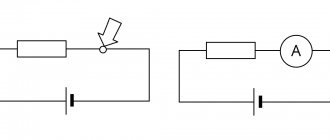
Switches on the plan are also displayed simply.
- A single-way open-mount switch is indicated by a circle and an outgoing poker.
- If there is more than one switch button, then hooks are added to the pattern.
- If the installation is hidden, then it is a circle with a lead and a strip across it; the more stripes, the more switches.
- If waterproof switches are installed, the circle is painted over.
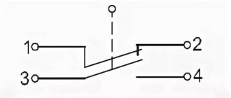
- If the switch is a pass-through switch, then the designation in the diagrams is different. One switch is a circle with an extending poker on both sides; hooks are added to the poker if there are more switches.
The blocks can be combined, that is, there is a switch and a socket in one place. Then the following notations apply:
- A semicircle with a stripe in the center and a stripe extending to the side with a line across it is a block with hidden installation, a single-way switch and an outlet without grounding.
- The ground contact is indicated by a line across the semicircle.
- If there are two switches, then the strips go in both directions. A block with one plug and one switch - indicated by a semicircle, a vertical stripe in the middle and a point to the side. Two switches are indicated by two leads from the semicircle and dashes across.
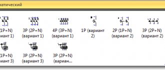
All information on the designation of switches and sockets in the diagrams is described in GOST 21.210-2014.
Sockets for hidden electrical wiring
Concealed wiring is the most common type of home electrical network. To install it, devices are used that are built into the wall using special mounting boxes.
USEFUL INFORMATION: Sockets for the kitchen in the countertop: hidden and built-in models
The only difference between the designation of such rosettes and the above figure is the perpendicular, lowered from the middle of the straight segment to the center of the circle.
Floor plan
These plans represent not so much the technical component of the project as the creative one, although at first glance it is not possible to think so. By selecting materials and, most importantly, the color of the floors, you can achieve impressive solutions, and most importantly, fulfill the task set by the customer: visually increase the area, create coziness, create zoning in a large space. Therefore, the floor plan, along with the layout, is an important part of the complete design project.
Devices with increased protection from dust and moisture
The sockets considered do not have a high level of protection against the penetration of solid objects into their housing, as well as moisture. Such products can be used in interior spaces where operating conditions exclude such effects. As for devices intended for installation outdoors or, for example, in bathrooms, according to the accepted classification, their degree of protection should be below IP44 (where the first digit corresponds to the level of protection against dust, the second - against moisture).
Such sockets are indicated on the diagram in the form of a semicircle completely shaded in black. As in the previous case, two-pole and three-pole waterproof sockets are indicated by the corresponding number of segments adjacent to the convex part of the semicircle.
Plan of lamps with references/groups
Also a very important element of the design of the project is a detailed plan for the location of lighting elements: from ceiling to wall lamps. Just as in the case of the location of sockets, the group membership, type (type) of the lamp is indicated, and ending with the connection to the switches. Switches can be single, double, or pass-through - when it is possible to turn the lighting on and off both at one end and at the other. These drawings may indicate devices for adjusting heated floors.
Switches
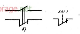
The switch in the diagram is indicated in the form of a circle, to which a line is drawn at an angle of 45 with an inclination to the right side, having one, two or three perpendicular segments at the end (depending on the number of keys of the switch depicted).
The image of the hidden installation switches is the same, only the segments at the end of the inclined line are drawn in both directions from it at the same distance.
Moisture-resistant products are indicated by a black circle.
It is worth paying attention to the image of pass-through switches, which resembles two ordinary switches, mirrored from the center of one circle.
Ceiling plan
An important part of the project is the ceiling plan. Modern technologies and materials make it possible to use parameters such as color, structure and shape of the ceiling to achieve the desired goals. Plus savings, which, while maintaining the effect, but using different materials, can significantly reduce the budget for installation and materials (paints, coatings).
Also important are the drawings themselves, which indicate the type and boundaries, indicate heights, spotlights and lamps.
Once a decision has been made and the ceiling consists of several levels, separate plans can be developed for the builders with the exact dimensions of the structure.
Socket blocks
Often, in terms of a home electrical network, it is necessary to provide for the installation of blocks that include different numbers of the most common elements - sockets and switches.
The simplest block, containing a two-pole socket and a single-key hidden switch, is depicted in the form of a semicircle, from the center of which a perpendicular is drawn, as well as a line at an angle of 45, corresponding to the single-key switch.
USEFUL INFORMATION: How to connect a telephone socket to a wire: wire color scheme
Blocks containing different numbers of sockets and switches are drawn on the diagram in a similar way. For example, a hidden installation unit, which includes a two-pole socket, as well as one-key and two-key switches, has the designation:
Thus, the designation of elements on an electrical diagram is carried out in such a way as to ensure the greatest ease in its preparation and reading. It is worth remembering the basic principles of constructing such circuits once, so that in the future you can easily use an apartment wiring plan of any complexity.
Necessity of the scheme
An electrical wiring diagram is necessary for its safe and high-quality placement.
For the purpose of high-quality and safe placement of electrical wiring, a plan is drawn up. It looks like a drawing to scale. The document reflects the layout of the apartment, the placement points of wiring units in groups, as well as circuit diagrams.
For understanding of the drawing by all participants in repair and installation work, sockets and switches are indicated by graphic drawings according to the all-Russian and global standard.
Geometric shapes are used as graphic markers - circles, squares, rectangles, dots and lines. Their combinations reflect the types of lighting system mechanisms and the features of controlling these devices.
Linking plumbing equipment
A separate drawing is a plan with plumbing connections. The moment when the installation is installed in bathrooms is especially important. This drawing is important for specialists who will install all equipment.
In the next part of the articles about the procedure for developing a design project , we will describe the final and, in the opinion of GIANT GROUP customers, the most enjoyable parts of visualization. As one of our clients said: “What can be clearly understood with the eyes, and not just drawings” - wall layout, 3D visualization of the design and drawing up a list of finishing materials.
Underfloor heating plan
If the customer wants to install heated floors, the design project includes their plan. Namely, taking into account the location of the furniture and the layout, the exact location is indicated and the binding of the thermostat is given. Its location can be indicated both on this plan and on the switch plan. Typically, heated floors are installed in those rooms where tiles (tiles, porcelain stoneware) are provided, namely the hallway, loggia, bathroom. If the room area is large (especially in cottages), the heated floor can be located in the living room, if the “finish” coating again involves tiles, etc.
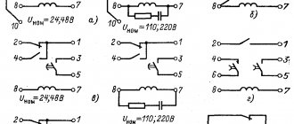
Graphic symbols of electrical equipment
To designate samples of electrical circuit equipment, the following standard symbols are used (Table 1).
The list of products presented in this table in the form of symbols includes:
- distribution boxes (branch boxes), installed in rooms for the design of branches to sockets and lighting fixtures;
- entrance and passage boxes;
- lighting panels (group and main);
- cabinets and panels for various functional purposes.
To designate input and linear or distribution machines, as well as standard energy meters (electricity meters), the following symbols are used:
In the final part of the review, we note that after familiarizing yourself with all the symbols discussed above, each user can easily understand the electrical wiring in his apartment.
Convenient location of sockets in the kitchen: photos and tips for choosing a location for installation
For built-in appliances, electrical sockets can be placed behind the walls of the furniture; the permissible height from the floor for this case is from 3 to 60 cm. To access the power source, holes are cut in the walls of the furniture set. Another valid rule: the electrical outlet for built-in appliances must be located at a distance of no more than 1 m from the device. Stationary appliances also include a range hood; the electrical socket for it is mounted 5 cm above the top edge of the kitchen furniture. When installing an electrical outlet, you need to take into account the location of the corrugated ventilation duct - it should not block access to the network. If we are talking about a built-in hood, it is better to place the outlet inside the cabinet, closer to the side wall (so that the exhaust pipe does not interfere).
In addition to stationary devices, the kitchen has appliances that are turned on from time to time. This is a toaster, mixer, kettle, coffee maker, bread maker, etc. To connect these devices, 3-4 free sockets are enough. They should be located in easily accessible places, for example, kitchen aprons or countertops. Electrical sockets for lighting kitchen furniture are located above the top line of the kitchen unit. Also popular is the option of a retractable socket block, which is mounted in the body of kitchen cabinets. Unlike electrical outlets (they should not be conspicuous), the switch must be placed in an accessible place.
When thinking through the kitchen electrical circuit, keep in mind that electrical outlets cannot be placed in the following places:
- Above the sink and stove.
- In cabinets with drawers and immediately behind the body of built-in appliances.
Conclusions and useful video on the topic
Overview of electrical elements using an example of a floor plan:
When installing electrical equipment, craftsmen of any level and direction should not have any misunderstandings with the designer who developed the power supply plan. Therefore, with all the variety of electrical products and methods of its application, graphic symbols on construction drawings and diagrams must have one general form and standard.
Please write comments in the block below. Share interesting information and information that will be useful to site visitors. Ask questions, express your own opinion on the topic and the material we offer, post photos.