USB pinout on the motherboard: what, where and how
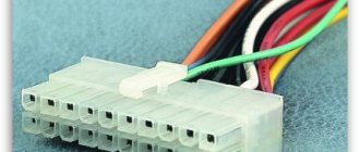
Most modern peripheral devices are connected via a universal serial bus. Therefore, the USB pinout on the motherboard plays a very important role in the operation of a modern computer. There are two ways to install these connectors. The first is mounting directly on the board. At the same time, it is displayed on the back side and is immediately ready for use. But it’s not always convenient to connect to it, so we developed another method. Its essence lies in a prepared footprint on the main PC board, to which wires from the front panel are connected. And the connector is located on it.
One USB 2.0 universal serial port has 4 pins. The first of them is designated “+5V”. It provides power to the peripheral device. The second and third are contacts through which information is transmitted. They are designated “DATA-” (minus data transfer) and “DATA+” (plus data transfer), respectively. The last one, the 4th one, which includes the USB pinout on the motherboard, is “GND” - ground supply. In accordance with today's standards, they are designated by the following colors: power - red, "DATA-" - white, "DATA+" - green, and "GND" - black.
Such interface connections are made in pairs, so the board has 2 USB standard connectors on one contact group. The wiring consists of 9 contacts: 4 to one connector, 4 to another, and the last two play the role of a so-called key. There is a pin installed in one place, but not in another. This is done so that it is impossible to confuse them and to make the connection correctly. The fitting from the front panel is made in a similar way. Therefore, when connecting, the first to the second should be installed without problems. If this does not happen, then you need to see if you are doing everything correctly.
Recently, version 3 of the USB standard has become increasingly popular. The pinout on the motherboard is significantly different, since significantly more wires are used to transmit information. There are only 9 of them in this design. In addition to the previously mentioned 4, 2 pairs of “Superspeed” + and 2 pairs of the same type, but only with a minus, are added, as well as “GND Drain” - additional ground. It is the larger number of wires that allows you to increase the data transfer speed. Their wires are designated blue by color, purple for minus, yellow, orange for plus, and another black for additional grounding. As the number of wires increases, the USB pinout on the motherboard increases in direct proportion. For this standard, 19 contacts are already used. One of them is a key, and its purpose is to ensure that the connection is correct.
Using the universal serial bus, a great variety of devices are connected to modern computers and laptops. A printer, scanner, MFP, flash drives, keyboard, mouse and other devices that significantly expand the capabilities of a PC - all of this is connected to the computer via this interface. It is not always convenient to connect to the back of the computer, and the number of integrated connectors may not be enough. It is to solve this problem that the USB pinout was made on the motherboard, which allows you to significantly increase the number of ports.
Connecting additional USB ports on your computer
USB is one of the most popular interfaces, used in the vast majority of devices. Almost any equipment is connected through it - from a regular mouse to a smartphone or gamepad. The problem is that sometimes there are so many devices that there are not enough connectors to connect them.
If nothing can be done with the laptop (the only option is to purchase a special adapter), then there is always the opportunity to install a couple of additional ports in the computer system unit. Let's see how to connect USB to a computer.
Connecting the front ports
Almost all modern system units are equipped with several USB connectors, which are located not on the back, but on the front panel. However, they usually do not work because they are not connected to the mother card.
Attention! All work is carried out with the computer turned off from the network.
Turn off the computer and remove the side cover. Locate the wires that come from the front of the system unit. They can be a coiled bundle of several thin cables or a solid wire.
Look carefully at the motherboard - there should be a connector on it, next to which it says USB (usually it is blue). Install the wire from the front ports into the motherboard connector. Assemble the system unit and turn on the computer. Now the front ports should work: you can, for example, connect Lenovo to a computer using them.
Installation of additional equipment
Do you want to connect a gamepad to your computer, but all the connectors, including the front ones, are occupied by other devices? Then you will have to purchase a USB controller that is installed in the PCI slot on the motherboard. If you connected a video card, you can easily install another card if there is a free slot.
If there are no free slots left on the motherboard, use external USB hubs.
Such devices are connected to an existing connector and allow you to seriously increase the number of ports. By installing several controllers and adding a number of hubs, you can increase the number of working USB ports to 127 (this is a protocol limitation; it simply won’t work anymore). Of course, the average user is unlikely to need such a number, but a couple of ports will never be superfluous.
Missing or incorrect installation of USB drivers
Causes associated with software problems in Windows 7/10 can be identified using Device Manager. If you notice that one or more devices in particular are not working, regardless of the port used, this may indicate that the problem is in the device itself. Open Control Panel and go to Device Manager. All connected devices will be displayed there. If there are items in the list that have a yellow exclamation mark next to them or the name is Unknown Device, then the problem is with this very device. There may be several possible problems here.
Often USB inputs stop working after reinstalling Windows 7/10. The reason is incorrect installation of drivers or the necessary drivers may not be found at all. You will have to select and install manually.
Often, to fix a problem you just need to update the drivers. So, if automatic Windows updates are disabled, and the system itself was installed quite a long time ago, then the relevance of the software is lost, and system errors may appear. In this case, the device begins to work incorrectly, or even stops functioning altogether. To update (reinstall) USB controller drivers, you can use a CD/DVD with drivers for the motherboard or download the necessary drivers from the motherboard manufacturer's website.
You can also turn off the power saving feature for all ports using Device Manager. Expand the list of used USB devices hidden in the sections “USB Controllers”, “Mouse and other pointing devices”, “Keyboards”. Double-click on the desired device to open the properties window. Now switch to the “Power Management” tab and uncheck the “Allow the computer to turn off this device to save power” checkbox. Thus, the device will always be activated under any circumstances.
If some equipment is not recognized, then there may be either a problem with the drivers already known to us, or a hardware problem, consisting of a lack of contact, a damaged cable, or a malfunction of the controller. Moreover, it often happens that when a faulty device is connected, the others stop working normally. The keyboard starts to freeze, as does the mouse, and the printer stops printing. The problem is similar to power shortage, that is, all the power consumption goes to a faulty device, which may have a simple short circuit or other malfunction.
- How to connect an asus motherboard to a case diagram
USB 2.0 connector pinout (types A and B)
Since the physical plugs and sockets of early versions 1.1 and 2.0 do not differ from each other, we will present the wiring of the latter.
Figure 6. Wiring the plug and socket of type A connector
Designation:
- A – nest.
- B – plug.
- 1 – power supply +5.0 V.
- 2 and 3 signal wires.
- 4 – mass.
In the figure, the coloring of the contacts is shown according to the colors of the wire, and corresponds to the accepted specification.
Now let's look at the wiring of the classic socket B.
Wiring of plug and socket type B
Designation:
- A – plug connected to the socket on peripheral devices.
- B – socket on a peripheral device.
- 1 – power contact (+5 V).
- 2 and 3 – signal contacts.
- 4 – ground wire contact.
The colors of the contacts correspond to the accepted colors of the wires in the cord.
Pinout of the main power cable connector
USB cable pinout diagram by color
The pinout of a computer's power supply starts with the largest and most important power cable - this is the cable connected to the motherboard. On old-style motherboards, the ATX connector is designed for 20 pins, while new generation motherboards already contain 24 pins in their connector. It is for this reason that new generation power supplies have cables with a 20+4 pin plug.
When pinouting a computer's power supply, it is important to know that the ATX plug is only suitable for powering the motherboard. This can be checked by looking closely at the contacts in the plug and connector - each of them is unique and suitable for only one purpose
USB ports not working due to controller damage
If none of the above actions helped restore the functionality of the USB ports, then you should check the USB controller of the motherboard, which may have failed. In this case, high-quality repairs and diagnostics should be entrusted to the specialists of the service center. As a way out of the problem, try installing an expansion card, the so-called USB PC controller, which is installed in the PCI slot on the motherboard. This solution is noticeably cheaper than repairing the motherboard USB controller, and when using an additional USB hub, the problem with the lack of ports will not be relevant at all.
Processor connection
The processor is the “heart” of the computer, without which it simply will not work. For the processor, there is a notch in the center of each motherboard called a socket.
Depending on the manufacturer of the processors for which they are intended, sockets come in two types:
- AMD. This variety has many small holes with contacts into which the “feet” located on the processor are immersed.
AMD processor
- Intel.
Here everything is the other way around: the legs are located on the socket itself, and there are flat copper contacts on the processor. Intel processor
To connect the processor, you need to carefully place it in the socket and close the latch. In this case, you need to be very careful, as you can bend or break one of the legs
There is nothing wrong with a bent leg; it can be carefully straightened with tweezers. But if the contact is broken, you will have to take the processor to a service center
Here is a video tutorial on connecting the processor:
USB device and purpose
Rj-45: pinout, diagrams, standards and description of the standard
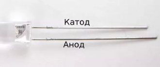
The first ports of this type appeared in the nineties of the last century. After some time, these connectors were updated to the USB 2.0 model. The speed of their work has increased more than 40 times. Currently, computers have a new USB 3.0 interface with speeds 10 times faster than the previous version. There are other types of connectors of this type, known as micro and mini USB, used in modern phones, smartphones, and tablets. Each bus has its own wiring or pinout. It may be required if you need to make your own adapter from one type of connector to another. Knowing all the intricacies of the arrangement of wires, you can even make a charger for a mobile phone. However, please remember that if connected incorrectly, the device may be damaged.
The USB 2.0 connector is designed as a flat connector with four pins. Depending on the purpose, it is labeled as AF (BF) and AM (BM), which corresponds to the common name “mother” and “father”. Mini and micro devices have the same markings. They differ from conventional buses in that they have five contacts. A USB 3.0 device looks similar to the 2.0 model, except for the internal design, which already has nine pins.
Benefits of use
USB connector (Universal Serial Bus) is a technology by which a peripheral device is connected to a PC or Mac. A USB connector is a convenient way to wire a gadget to a computer. Let's take a closer look at what USB is.
Advantages of using a serial universal bus.
- Prevalence. Each PC has on average 2-4 such inputs, which allows you to connect several devices at once. This prevalence has been observed for a long time.
- Easy to use. The user does not have to worry about drivers; no effort is required. The operating system automatically connects the necessary drivers to “see” the peripheral device. The user just needs to connect the USB cable, and the computer will do the rest.
- High throughput. This allows you to exchange files at good speed. There is no need to wait 2-3 hours for the selected file to be saved to your computer. This operation takes from 5-10 seconds to 10 minutes (depending on the size of the document). The exact speed depends on the type of USB.
- Charger. In addition to the basic viewing and transmission functions, an additional one is available - recharging. When you connect your phone to your computer via USB, the device starts charging automatically. The speed at which power is received through the computer is less than the speed at which power is supplied through the charger. And there is not always an outlet at hand.
The technology helps the user connect with the computer in minimal time. It’s convenient to plug the cable into the USB output and get started.
Connect the USB connectors on the front panel of the case to the motherboard
Hello friends! The USB interface has become firmly entrenched in the life of any computer user. Thanks to its versatility and ease of use, you can use it to connect a lot of devices - a table lamp, a fan, a gamepad, a gaming wheel, a flash drive, an external hard drive and much more.
Frequent use of ports located on the rear side is not always convenient, as access to them can be difficult. Currently, most cases are equipped with USB ports on the front panel, the number of which may vary depending on the model.
Connecting the system unit to the Internet
To connect your computer to the Internet, you need to use the network port on the motherboard.
Connect the Internet cable (twisted pair) or patch cord to the router, and its second connector to the RJ-45 connector on the motherboard. When you turn on your computer, the router will assign an IP address to your PC, and the operating system will automatically configure the built-in network card on the motherboard.
That's it, after connecting external devices to the system unit, you can turn on the computer. Don't forget to turn on the power supply.
Characteristics
Reviews
Discounts
Go to the Market section
Product not found! Reset the filter or refine your query.
How to connect wires to a computer
*Video may differ from the topic of the article
USB 3.0 pinout types A and B
Bus version 3.0 has a 10 or 9 wire connection. 9 pins are used if Shield wire is missing. The contacts are arranged in such a way that devices of earlier modifications can be connected.
USB 3.0 wiring:
- A – plug;
- B – socket;
- 1, 2, 3, 4 – contacts that match the pinout of the contacts in specification 2.0, have the same color scheme;
- 5, 6 contacts for data transmission via the SUPER_SPEED protocol are designated SS_TX- and SS_TX+, respectively;
- 7 – grounding GND;
- 8, 9 – contact pads of wires for receiving data via the SUPER_SPEED protocol, contact designation: SS_RX- and SS_RX+.
The USB Pinout:
| Pin | Name | Cable color | Description |
| 1 | VCC | Red | +5 VDC |
| 2 | D- | White | Data - |
| 3 | D+ | Green | Data + |
| 4 | GND | Black | Ground |
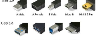
USB connectors
There are several types of USB connectors. The connector mounted on the host or device is called the receptacle, and the connector attached to the cable is called the plug. The original USB specification detailed Standard-A and Standard-B plugs and receptacles. Nowdays there are 7 USB connectors known: Standard-A, Standard-B, Mini-A, Mini-B, Micro-A, Micro-AB, Micro-B, Type-C. Mini-USB pinout and Micro-USB pinout are slightly different: standard USB uses 4 pins while Mini-USB and Micro-USB uses 5 pins in connector. The additional pin is used as an attached device presence indicator.
USB pinout signals
USB transfer modes
Universal serial bus supports Control, Interrupt, Bulk and Isochronous transfer modes.
USB interfaces specifications.
There are some major USB versions known nowdays:
USB 1.0 - Low Speed or Full Speed
- released in 1996.
- Specifies data rates of 1.5 Mbit/s (Low-Bandwidth, is mostly used for Human Input Devices (HID) such as keyboards, mice, joysticks and often the buttons on higher speed devices such as printers or scanners) and 12 Mbit/s ( Full-Bandwidth).
- nowadays is still used by some devices that don't need faster data transfer rates.
USB 2.0 - High Speed
- released in 2000
- in addition to USB 1.0 adds signaling rate of 480 Mbit/s (Hi-Speed)
- compatible with USB 1.0, but some hardware designed for USB 2.0 may not work with USB 1.0 host controllers.
USB 3.0 - SuperSpeed
- released in 2008
- added transmission rates up to 5 Gbit/s (SuperSpeed)
- USB 3.1 released in 2013 added SuperSpeed+ transmission rate up to 10 Gbit/s
- USB 3.2 released in 2022 added SuperSpeed+ transmission rate up to 20 Gbit/s and multi-link modes
USB 1.0 and USB 2.0 shares same connector pinout, USB 3.0 pinout and USB Type C features new connectors with their own pinouts.
An USB device must indicate its speed by pulling either the D+ or D- line high to 3.3 volts. These pull up resistors at the device end will also be used by the host or hub to detect the presence of a device connected to its port. Without a pull up resistor, USB assumes there is nothing connected to the bus.
In order to help user to identify maximum speed of device, a USB device often specifies its speed on its cover with one of the USB special marketing logos.
When the new device first plugs in, the host enumerates it and loads the device driver necessary to run it. The loading of the appropriate driver is done using a PID/VID (Product ID/Vendor ID) combination supplied by attached hardware. The USB host controllers have their own specifications: UHCI (Universal Host Controller Interface), OHCI (Open Host Controller Interface) with USB 1.1, EHCI (Enhanced Host Controller Interface) is used with USB 2.0.
USB powered devices
The USB connector provides a single 5 volt wire from which connected USB devices may power themselves. A given segment of the bus is specified to deliver up to 500 mA. This is often enough to power several devices, although this budget must be shared among all devices downstream of an unpowered hub. A bus-powered device may use as much of that power as allowed by the port it is plugged into.
USB 3.0 pinout (types A and B)
In the third generation, peripheral devices are connected via 10 (9 if there is no shielding braid) wires; accordingly, the number of contacts is also increased. But they are located in such a way that it is possible to connect devices of earlier generations. That is, the +5.0 V contacts, GND, D+ and D-, are located in the same way as in the previous version. The wiring for Type A socket is shown in the figure below.
Figure 8. Pinout of Type A connector in USB 3.0
Designation:
- A – plug.
- B – nest.
- 1, 2, 3, 4 – connectors fully correspond to the pinout of the plug for version 2.0 (see B in Fig. 6), the colors of the wires also match.
- 5 (SS_TX-) and 6 (SS_TX+) connectors for data transmission wires via the SUPER_SPEED protocol.
- 7 – ground (GND) for signal wires.
- 8 (SS_RX-) and 9 (SS_RX+) connectors for data receiving wires using the SUPER_SPEED protocol.
The colors in the figure correspond to those generally accepted for this standard.
As mentioned above, a plug from an earlier model can be inserted into the socket of this port; accordingly, the throughput will decrease. As for the plug of the third generation of the universal bus, it is impossible to insert it into the sockets of the early release.
Now let's look at the pinout for the type B socket. Unlike the previous type, such a socket is incompatible with any plug of earlier versions.
Wiring USB 3.0 type B
Designations:
A and B are plug and socket, respectively.
Digital signatures for contacts correspond to the description in Figure 8.
The color is as close as possible to the color markings of the wires in the cord.
Tsokolevka
The layout of the USB connector depends on the specification of this interface of its types
They are visually different and in order not to confuse them when connecting to equipment, pay attention to the following: A – for a computer or hub; B – for a peripheral device. The first versions of connectors (up to USB2.0) were physically no different from each other and had four contacts: 1.4 – for supplying plus (+5 V) and minus (Gnd) supply voltage; 2.3 – for differential data transmission
For clarity, we present their images and pinouts in the figure.
USB3.0 also has two types of connectors A and B. Both are equipped with nine pins, while the first four are fully backward compatible with version 2.0 discussed above. Five additional contacts have the following purposes: 5-6 receive (RX), 8-9 transmit (TX) data; 7 – additional signal grounding (Gnd-Drain).
The wires of the USB cable have different colors, in the pictures above you can see which color is used for transmitting signals and which for power. All types of USB have additional modifications for use in portable mobile devices. These miniature connectors are designated by the words “mini” or “micro”. We encounter them everywhere in everyday life and use them to recharge cell phones and other mobile gadgets.
Pinout of USB 2.0 connector types A and B
Classic connectors contain 4 types of contacts, while mini and micro formats contain 5 contacts. Wire colors in USB 2.0 cable:
- +5V (red VBUS), voltage 5 V, maximum current 0.5 A, intended for power supply;
- D- (white) Data-;
- D+ (green) Data+;
- GND (black), voltage 0V, used for grounding.
For mini format: mini-USB and micro-USB:
- Red VBUS (+), voltage 5 V, current 0.5 A.
- White (-), D-.
- Green (+), D+.
- ID - for type A it is closed to GND to support the OTG function, but for type B it is not used.
- Black GND, voltage 0V, used for grounding.
Most cables have a Shield wire; it has no insulation and is used as a shield. It is not marked and is not assigned a number. The universal bus has 2 types of connectors. They are designated M (male) and F (female). Connector M (male) is called a plug, it is inserted, connector F (female) is called a socket, it is inserted into it.
Pinout features
When talking about the pinout of a USB connector, you need to understand the symbols indicated on the diagrams. It’s worth starting with the type of connector - active (type A) or passive (type B). Using an active connector, information can be exchanged in two directions, and a passive connector only allows it to be received. You should also distinguish between two forms of connector:
- F - "mother".
- M - "dad".
USB connector
First, a few words need to be said about the compatibility of the three versions of the interface. Standards 1.1 and 2.0 are completely similar in design and differ only in the speed of information transfer. If one of the parties in the connection has a higher version, then work will be carried out at low speed. The OS will display the following message: “This device is capable of running faster.”
With compatibility between 3.0 and 2.0, everything is somewhat more complicated. A device or cable of the second version can be connected to the new connector, and backward compatibility exists only for active type A connectors. It should be noted that the USB interface allows you to supply a voltage of 5 V to the connected gadget with a current of no more than 0.5 A. For the USB standard 2.0, the color layout from left to right is as follows:
- Red - positive contact of constant voltage of 5 V.
- White - data-.
- Green - data+.
- Black is the common wire or ground.
The connector circuit is quite simple, and if necessary, repairing it will not be difficult. Since version 3.0 has increased the number of contacts, its pinout also differs from the previous standard. Thus, the color scheme of the contacts is as follows:
- Red - 5 V+.
- White - data-.
- Green - data+.
- Black is common.
- Purple - welcome.
- Orange - reception+.
- Without color - earth.
- Blue—transmission-.
- Yellow - transmission+.
Micro and mini connectors
Connectors of this form factor have five contacts, one of which is not always used. Conductors of green, black, red and white colors perform similar functions to USB 2.0. The mini-USB pinout corresponds to the micro-USB pinout. In type A connectors, the violet conductor is shorted to the black, but in passive connectors it is not used.
Miniaturization of the connector had a negative impact on reliability. Although mini-USB has a large resource, after a fairly short period of time it begins to dangle, but does not fall out of the socket. Micro-USB is a modified version of mini-USB. Thanks to the improved fastening, it turned out to be more reliable. Since 2011, this connector has become a unified standard for charging all mobile devices.
However, manufacturers are making some changes to the scheme. Thus, the pinout of the micro-USB connector for charging the iPhone involves two changes compared to the standard one. In these devices, the red and white wires are connected to the black through a resistance of 50 kOhm, and to the white - 75 kOhm. There are also differences from the standard for Samsung Galaxy smartphones. In it, the white and green conductors are closed, and pin 5 is connected to pin 4 using a 200 kOhm resistor.
USB 3.0 and other subtleties
However, this is true in cases where ports of the same generation are used.
If the motherboard has a second or third revision, and a similar situation is observed with the front panel, compliance is necessary: USB 3.0 should be connected only to the corresponding slot on the motherboard, otherwise it will operate at USB 2.0 speed.
There is no need to worry about the pinout: it is the same for both revisions. In addition, motherboard manufacturers - ASUS, MSI, Gigabyte, Asrock and smaller companies, follow the same pinout that case manufacturers follow.
However, keep in mind that in rare cases it may still differ from the generally accepted one. You can find out the necessary information in the documentation for the motherboard.
Do not worry that you can connect the USB port incorrectly - in this case it simply will not work. Fortunately, it is impossible to break your computer this way.
USB data rates
USB is a standard, and it defines the maximum speed at which signals can be transmitted through a port. The USB 2.0 standard provides a theoretical maximum signal transfer rate of 480 megabits per second. While USB 3.0 allows data transfer at a speed of 5 gigabits per second. In theory, USB 3.0 is ten times faster than USB 2.0.
USB 3.0 speed test
USB 2.0 drives are capable of writing speeds from 7.9 to 9.5 MB/s, while USB 3.0 drives range from 11.9 MB/s up to 286.2 MB/s. We see that the worst USB 3.0 drive is faster than all USB 2.0 drives, but not by much. And the best one is more than 28 times faster.
USB 3.0 drive speed test results
The slowest drives were the cheapest, while the faster ones were expensive. The fastest media achieves this speed thanks to four-channel flash memory, which requires some investment from the manufacturer.
As you can see, there are quite a lot of differences, but each has its own nuances. Now you know how to distinguish USB 2.0 from USB 3.0. Please note that not all devices will be faster just because they use USB 3.0. Before you buy the device you need, pay attention to other parameters that will be critical, such as flash memory speed.
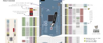
How to properly connect the front panel to the motherboard
Often, a person who is assembling a computer for the first time (and it happens that it is not the first time) is faced with the fact that he does not know how to correctly and where to connect reset buttons, power buttons, LED indicators, a speaker that makes a squeak when turned on . I will show several examples by which you can understand the principle of how any front panel is connected correctly, and I will tell you some secrets that I use in my work.
There is nothing complicated about this if you adhere to simple rules and recommendations, which will be discussed now.
Where to connect the connectors?
This section is for those who do not know where exactly the front panel is connected. If this doesn't apply to you, skip straight to the next section and read on.
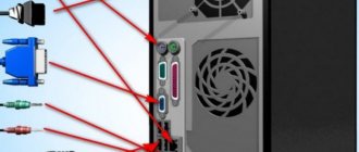
First, let's figure out what the place on the motherboard where the front panel of the computer is connected generally looks like. For clarity, I just want to show a few photos, from them you can easily determine what this connector looks like on the motherboard:
As you can see, they may differ slightly from each other
I also want to draw your attention to the fact that the location at the bottom right is not mandatory; sometimes these contacts are located in the center at the bottom of the motherboard
How to properly connect the front panel connectors?
Most motherboards already have markings on what to connect and where. Here is the simplest and most obvious example:
From left to right in the photo:
+MSG- (yellow) – connection of the computer operation indicator;
+HD- (blue color) – connection of the hard disk drive (HDD) operation indicator;
+PW- (red color) – connection of the power button;
-RES+ (green color) – connection of the reset button;
+SPEAK- (orange color) – connecting a speaker (the one that makes a squeak when turned on);
The colors don’t mean anything here, the manufacturer just decided to make such markings.
Rules for connecting connectors:
There are simple general rules, using which you will correctly and easily connect the front panel connectors to the motherboard:
Connecting the Power and Reset buttons has no polarity, since these buttons simply work to close the contacts
Despite the fact that the board indicates + and – for these buttons, they have no meaning. It is important to observe the polarity when connecting the LEDs and the speaker, otherwise they will not work. On the motherboard, for each type of connector, its plus is always on the left, and its minus is on the right. This is true for all motherboards
Connecting buttons and indicators
The power buttons and computer operation indicators will connect to a set of pins, which on the motherboard is usually labeled as F_PANEL. The diagram below should help you with the connection.
- Power button - designated as MB, POWER, POWER-SW, PW.
- Reset button - usually designated as RES, RESET, RESET SW.
- Disk activity indicator - usually referred to as HD, HDD, HDD LED.
- Power indicator - usually referred to as PLED, POWER LED.
Sometimes, the connector with pins for the front panel may have a more elongated shape:
In this case, you need to focus on the left side of the connector, which completely corresponds to the diagram above.
OTG - DIY adapter
Connector pinout of ethernet connector cable connection diagram
Not all old tablets support the function of connecting a flash drive or modem, but I will tell you how to outsmart them and connect a flash drive, modem, or even a hard drive to them. Good afternoon, homemade people!
Today I would like to present to your attention an OTG adapter.
First, I want to tell you what OTG is? This is a way to connect to your tablet or phone that supports the OTG function, printer, flash drive and even hard drive. This connection is also called USB-host.
You can also connect a keyboard or mouse to your gadget, if the gadget supports such a function.
And so, to create this miracle cable, we will need: • An old USB extension cord • Micro USB connector (you can get it from a regular USB cable for your device) • A soldering iron and soldering accessories
And so, let's go, to make such a cable, we will need to connect the 4th pin to the 5th pin of the micro USB connector
We must get to the fourth pin and connect it with a jumper to the GND wire as shown in the picture
After we connect the 4th and 5th contacts with a jumper, our gadget will perform the function of an active device and will understand that another passive device is about to be connected to it. Until we install a jumper, the gadget will continue to act as a passive device and will not see your flash drives.
But that’s not all; to connect a hard drive to a phone or tablet, this adapter will not be enough for us. To connect devices whose consumption is more than 100mA, namely 100mA can be supplied by the port of your device, we will need to connect additional power to our OTG cable, which should be enough for your hard drive to work.
Here is a diagram of such an adapter
Now it's time to start assembling. We take the old USB extension cable and cut it not too far from the 2.0 connector, since the current is only 100mA, to avoid large losses. Cut approximately in the same place as shown in the photo
Afterwards we clean our wire
Next, it needs to be tinned and soldered as shown in the diagram. You need to tin approximately 1mm of the wire, since the contacts on the micro USB connector are very small. This is what happened to me.
I connected pins 4 and 5 with a drop of solder.
Well, here is our entire cable assembled
All that remains is to check the functionality, take the tablet, insert the “adapter” and insert the flash drive into it, everything works, as the flashing LED on the flash drive and the tablet detecting the flash drive tell us.
Limitations: Old mobile phones cannot do this. The flash drive must be formatted in FAT32. The maximum capacity of the connected flash drive is limited by the hardware capabilities of the phone or tablet.
Types of damage
There are different types of damage, so further actions depend on the type of fault. If the connector is faulty, you will have to buy a new micro USB or look for a broken device with a working socket and replace it. When a working USB simply comes off, it is enough to restore the connections with a soldering iron. If the plug on the cable malfunctions, you need to buy and solder a new one.
The connector turned out to be faulty
In this case, you need to find a known-good connector, for example, on a non-working cell phone. Micro USB will have to be soldered; to do this, insert a scalpel between the board and the connector. You need to unsolder the mounting tabs from the board, and then unsolder the micro USB pin, heating them at the same time.
In this case, it is necessary to monitor the temperature so as not to deform the plastic parts. The thinner the soldering iron tip, the less chance there is of damaging the connector.
You should pay attention to the location of SMD parts during installation, since reverse installation is somewhat more complicated. USB soldering is done in reverse order
The working connector came off
It is necessary to check the integrity of the tracks on the board by inspecting them with a magnifying glass. All damage will have to be repaired. To do this, first remove the varnish with a scalpel, and then tin the paths with a soldering iron. Soldering a micro USB connector begins with attaching the mounting tabs. Before this, you can glue the connector to the board to make a break less likely.
If other damage remains, then take thin copper wires and secure them between the terminals of the tracks and USB. If they are not fully restored, only the charging function will be retained (without the possibility of data transfer). Also, the connected mouse will not work. If you are sure that everything has been restored correctly, then this indicates a malfunction of the USB itself.
Flash memory problems
If the connected flash drive does not work, you should first check its functionality by connecting it to other known working devices. If a working drive does not work only with a repaired device, it means that errors were made during the repair.
Most likely, some damage to the bridges was not noticed - the hull needs to be disassembled again and inspected. If everything is visually in order, it means that the malfunction is hidden, and further disassembly is performed only if it is not a pity to completely lose the device and waste time.
Types of USB connectors - main differences and features
There are three specifications (versions) of this type of connection that are partially compatible with each other:
- The very first version that has become widespread is v 1. It is an improved modification of the previous version (1.0), which practically did not leave the prototype phase due to serious errors in the data transfer protocol. This specification has the following characteristics:
- Dual-mode data transfer at high and low speed (12.0 and 1.50 Mbps, respectively).
- Possibility of connecting more than a hundred different devices (including hubs).
- The maximum cord length is 3.0 and 5.0 m for high and low transfer speeds, respectively.
- The rated bus voltage is 5.0 V, the permissible load current of the connected equipment is 0.5 A.
Today this standard is practically not used due to its low throughput.
- The dominant second specification today... This standard is fully compatible with the previous modification. A distinctive feature is the presence of a high-speed data exchange protocol (up to 480.0 Mbit per second).
A clear demonstration of the advantages of USB 2.0 over other interfaces (transfer speed 60 MB per second, which corresponds to 480 Mbit per second). Thanks to full hardware compatibility with the younger version, peripheral devices of this standard can be connected to the previous modification.
True, the throughput will decrease up to 35-40 times, and in some cases more. Since these versions are fully compatible, their cables and connectors are identical.
Please note that, despite the bandwidth specified in the specification, the actual data exchange speed in the second generation is somewhat lower (about 30-35 MB per second). This is due to the implementation of the protocol, which leads to delays between data packets. Since modern drives have a read speed four times higher than the throughput of the second modification, that is, it does not meet current requirements
Since modern drives have a read speed four times higher than the throughput of the second modification, that is, it does not meet current requirements.
- The 3rd generation universal bus was developed specifically to solve problems of insufficient bandwidth. According to the specification, this modification is capable of exchanging information at a speed of 5.0 Gbit per second, which is almost three times the reading speed of modern drives. Plugs and sockets of the latest modification are usually marked blue to facilitate identification of belonging to this specification.
USB 3.0 connectors have a characteristic blue color.
Another feature of the third generation is an increase in the rated current to 0.9 A, which allows you to power a number of devices and eliminate the need for separate power supplies for them.
As for compatibility with the previous version, it is partially implemented; this will be discussed in detail below.
Connecting a car recorder via DCDC and pinout the power cable
Connector pinout of ethernet connector cable connection diagram
I'm tired of having a recorder and a lot of other crap stuck in the car's cigarette lighter all the time. So a bright idea came to my mind that it was necessary to remove all the ugly wires and finally make it beautiful. Look how black and white the poop is in the area of the right visor.
I bought 2 mini USB cables twisted into a spiral (you may have others! Check), a DCDC pulse converter with a voltage regulator and a peak load of 3A (or better yet, 5A and then nothing will get hot) and some small items for convenience. Chinese DCDCs do not dissipate heat well, so I took a small heatsink for the video card chips and attached it to a pad that dissipates heat. Next, it remains to solder the USB connector and the general power connector to make it convenient to disconnect and repair
Please note that to power the recorder, the voltage must be increased to 6 volts and nothing else can be inserted there under the threat of device failure. Just in case, measure the power supply voltage of your recorder. What if it will be different from my 6 volts? If the converter will be used to charge mobile phones and tablets, then you need to set it to strictly 5 volts
Don't forget the fuse! 4A will be enough. Regular cables are not as convenient, so I bought a spiral cable with micro usb. It looks cool and will stretch if you happen to pick up the phone. Total advantages!
What if it will be different from my 6 volts? If the converter will be used to charge mobile phones and tablets, then you need to set it to strictly 5 volts. Don't forget the fuse! 4A will be enough. Regular cables are not as convenient, so I bought a spiral cable with micro usb. It looks cool and will stretch if you happen to pick up the phone. Total advantages!
Now for all this crap to work, to power the recorder, you need to modify the USB cable so that the recorder considers my power source not a computer, but an original power supply. If your recorder, when connected to such a cable, does not try to switch to computer mode, then you do not need to do anything. I gave links to cables above. They are very easy to disassemble and re-solder as needed. Use this if you don't want to assemble the cable entirely by hand.
Wiring diagram for the cable you purchased:
It needs to be modified as follows: 1 – not used 2 – not used 3 – not used 4 – (not indicated by a number in the picture) (+6V). 5 – (in the picture as No. 4) (-) mass.
Those. Basically, you just need to transfer the power wire (red) from one contact to another, and just cut off the rest. Observe polarity! In the picture above, the sockets (female) are shown on the left, and the plugs (male) are shown on the right. Don't overheat the wires! The insulation on them melts very easily! Check the cable for a short circuit with a tester and insulate the soldered wire with heat shrink. During operation, the wire I soldered came off and shorted with another. As a result, the DCDC converter burned out. Now I not only insulated the wires, but also filled the entire connector with a compound to prevent vibration.
If during disassembly you accidentally damaged 1 of the 4 locks, you can simply solder the connector as in the photo above. I only broke 1, but decided to play it safe. You never know what will happen on the road. There is no need to modify the cable for your tablet or phone!
In the end, I ended up with this assembly. The second photo shows a new DCDC with a fuse and a voltmeter/amperemeter.
The power source will be placed in my cavity above the walkie-talkie and 2 wires will come out of it on the sides to power the recorder and power the tablet.
If the tablet consumes more than 1A while charging, then buy a more powerful DCDC. Just in case, I ordered a separate 5A DCDC from DX, which I will install later next to the first one.
If you are passionate about talking on the radio with other people, then read my articles about the Baofeng UV-5RA wearable VHF radio and about installing a Megajet radio in the interior of a restyled Niva Chevrolet. I have already exchanged the Megajet MJ-350 for the MJ-600+ turbo and they are no different in the design of the holder.
The USB interface is a popular form of technological communication on mobile and other digital devices. Connectors of this kind are often found on personal computers of various configurations, peripheral computer systems, cell phones, etc.
A feature of the traditional interface is the USB pinout of a small area. For operation, only 4 pins (contacts) + 1 ground shield line are used. True, the latest more advanced modifications (USB 3.0 Powered-B or Type-C) are characterized by an increase in the number of working contacts. This is what we will talk about in this material. We will also describe the structure of the interface and the features of cable wiring on the connector contacts.
Options to add a USB-C jack for laptop users
If your laptop doesn't have USB-C ports and you need to connect something to it, the easiest way to do it is to use a simple cable. USB-C to USB-A cables (with a standard rectangular connector) are available in male and female versions. In fact, if your new gadget only connects via USB-C, like most new Android phones, it's likely that a C-to-A cable was included in the box. You can buy this very inexpensively at any electronics store.
Standard USB-A to USB-C cable.
When using these cables for anything other than charging, be sure to connect them to a USB 3.0 port. Ports 3 (and later) are not the same as ports A and C: the number refers to the version of the Universal Serial Bus, and the letter refers specifically to the shape and digital pins in the connection. Ports 3.0 and higher offer significantly faster speeds than the old 2.0 standard. 3.0 ports are sometimes marked with blue connectors or other obvious color changes or a symbol like this:
Main motherboard ports and their pinouts
The contacts present on motherboards can be divided into several groups: power connectors, connections for external cards, peripheral devices, and coolers, as well as front panel contacts. Let's look at them in order.
Nutrition
Electricity is supplied to the motherboard through a power supply, which is connected through a special connector. In modern types of motherboards there are two types: 20 pin and 24 pin. This is what they look like.
In some cases, four more are added to each of the main contacts to make the units compatible with different motherboards.
The first option is older; it can now be found on motherboards manufactured in the mid-2000s. The second one is relevant today and is used almost everywhere. The pinout of this connector looks like this.
By the way, by closing the PS-ON and COM contacts, you can check the functionality of the power supply.
PSU connectors
The power supply contains the main connectors (electrical connectors) previously used in old power supplies, supplying voltages of 3.3, 5 and 12 Volts.
Each connector pin is one Pin. Motherboard
connects to the power supply via a 24 Pin male connector (the so-called bus), which has undergone changes with the improvement of motherboards. Previous generations of motherboards were connected to the power supply via a 20 Pin bus.
Because of this, in order to support any type of connection to the motherboard, the connector is made in the form of a collapsible design with a 20 Pin main and 4 Pin additional power connector.
If the motherboard only needs 20 Pin, the 4 Pin connector is removed (pull down along the plastic rails) and bent to make it easy to install a 20-pin bus.
Molex 8981 connectors are used to power optical drives and other drives with a PATA (Parallel ATA) connection interface.
(by the name of the developer-manufacturer company).
SATA (Serial ATA) connection interface
for storage devices of all types.
Typically, to power storage devices
, the power supply has two special 15 Pin connectors (or there is an adapter for powering PATA HDD - SATA HDD).
Central processor
Requires power supply from a 4 or 8 Pin connector (can be detachable).
Video card
You need 6 or 8 Pin power. The connector can be dismountable to 6+2 Pin
Some modern power supplies may contain an outdated 4 Pin connector for floppy drives
, card readers, etc.
Also 3 and 4 Pin connectors are used to connect coolers
.
Connecting the front panel of the computer to the motherboard
If you decide to assemble or disassemble a computer, this article will be very relevant for you. It will discuss how to properly connect the panel of front buttons and USB ports on the system unit to the motherboard. Here, I will consider not only the general appearance of the ports to which they need to be connected, but also the correct order when connecting them.
In fact, there seems to be nothing complicated about this. But in my practice, even specialists who are fairly well versed in computer technology sometimes stand in front of a system unit with a bunch of cables and think about what needs to be connected and where.
Therefore, below I will show in detail what and in what connector this or that wire needs to be connected for the correct operation of the connected front panel of the system unit. That in the future, the next time you clean your computer or perhaps replace the motherboard, it will not be difficult for you to correctly connect all the elements of the system unit to the motherboard.
It is also very important if the front panel with USB ports and outputs for headphones and microphone does not work. Then, be sure to read it to the end to find out how to fix this whole thing and return our front USB ports to working condition. Because the problem may lie in the fact that they are simply not physically connected to the motherboard.
Connecting the front panel, button block and indicators
The block of buttons and light bulbs for turning on and rebooting is connected to the motherboard using four connectors, which are connected into one continuous cable. You can see what they look like for me below. They should have approximately the same appearance for you. The main thing is to look for those connectors that have similar phrases written on them: Power SW, Power LED, HDD LED. RESTART SW.
Let's look at each connector separately:
- POWER SW (PWRBTN) - is responsible for the computer power button;
- HDDLED (+HDLED) - a hard drive light that constantly blinks when the computer is running;
- POWER LED - and + (PLED) - indicator indicating the state of the computer (on or off);
- RESTART SW (RESET) - connector responsible for the reset button;
- SPEAKER - a tweeter speaker is sometimes also present in the cable panel;
Where should all this be connected? All connectors will connect to one port, which is located in the lower right corner of the motherboard. Manufacturers usually sign them with such designations as: “F_PANEL” or simply “PANEL”. On each motherboard, near such a panel, there are small signatures where what needs to be inserted. But still, below I will give you several examples of what to add to what.
Also, sometimes an additional small speaker is connected which notifies with a squeak that the computer is turned on, as well as about various BIOS and computer hardware errors. Sometimes it is connected with all the other connectors, but as a rule, a separate four-pion connector is allocated for it.
That's it, we're done with the button block, now we can move on to the front USB and audio outputs.
System unit front panel connections
The audio and USB connectors are very similar to those we connected for buttons and indicators. But their most important difference is that they are already immediately connected into one, and when connecting you do not need to take it and connect it one pin at a time.
You can also find the place for connection at the bottom of the motherboard with labels (F_USB1, 2). There may be two or more of them on the motherboard, but it doesn’t matter which one you connect to, they will work the same. The main thing you need to do is take the connector labeled “F_USB” and put it in the appropriate connector. You can’t make a mistake, because if you try to insert it the wrong way, you simply won’t succeed, and turning it over to the other side, I think everything should fall into place.
Be sure to pay attention if you have USB 3.0 on the front panel of your computer, then you will need to connect it to the appropriate connector. You can find out where it is located in the manual for your motherboard. Also, I want to draw your attention to the fact that if USB 3.0 is connected to a standard connector, it will work, just the transfer speed will be the same as on USB 2.0.
Connecting the front audio panel to the motherboard
The situation with sound is similar to USB. Here, too, the connectors are connected into one, which will allow you to easily and without errors connect it to the motherboard. The connector itself is usually located next to the USB ports and is designated by the following abbreviations; AAFP, AUDIO, A_AUDIO.
Taking a connector with the inscription “HD Audio” or “AC 97”, we connect it to the connector with one of the signatures, an example of which I indicated above. If after connecting the headphones and microphone still do not respond, then you should check the settings of the front audio panel in the BIOS. Sometimes it happens that the system uses the “AC97” driver, but the BIOS indicates “HD Audio”, which, due to mismatch, renders our audio outputs inoperative.
Preparatory stage
The front panel, as well as additional USB connectors, are installed on the motherboard after the main work on assembling and setting up the PC has been completed. Before installation, it is advisable to examine all the free connectors on the motherboard and the cables with which the front panel will be connected.
If you connect the cables to the wrong connectors and/or in the wrong order, you risk disrupting the functionality of the entire computer. It is advisable to find and carefully study the documentation for the motherboard and front panel, even if it is not written in Russian.
All elements on the motherboard and front panel have their own markings, so if you carefully study the documentation, you will not confuse anything. It is also worth understanding that the instructions described in the article are of a general nature, since the features of your motherboard may differ from generally accepted standards.
Stage 1: Connecting indicators
If you are connecting the front panel, then this step is mandatory. Those who connect an additional expansion board with USB connectors should pay attention to the design of this board. If it contains any indicators and buttons, then you should not skip this stage. If there are just connectors, then you only have to connect the cable responsible for the power supply.
Before starting work, disconnect the computer from power. Now you need to find a special block located on the motherboard. Usually, it has a special designation and one of the signatures - “Front Panel”, “F_Panel” or “Panel”. It can also be found by location, since it is located as close as possible to the expected location of the front of the system unit.
Now let's look at the connecting wires that you may encounter both on the front panel unit and on the unit with additional USB connectors:
- The red wire is used to connect the on/off button;
- The yellow wire is responsible for the operation of the reset button;
- The blue cable is responsible for the operation of the system reboot/boot indicator;
- The power indicator depends on the green wire;
- To connect the panel to power, you need to use a white cable.
On some models, the functions of the red and yellow wires may change between each other, which can cause confusion. Fortunately, such models come across very rarely, and this feature is always written in the instructions.
Stage 2: Connecting the connectors
At this stage, you need to correctly connect the USB and audio connectors to the contacts on the motherboard. Cables and their connection points are marked accordingly. For example, the connection location is usually marked F_USB1, F_USB2, etc. It is worth understanding that there may be several such ports on the board. In this case, the order in which the cables are connected to them does not matter.
In the case of older versions of USB, everything is quite simple - connect the cables to special connectors on the motherboard and that’s it. But if you connect USB version 3.0 and higher, then you will have to connect it only to certain connectors. You can find out which ones exactly by using the documentation for the motherboard or board with additional connectors. Also, modern boards have special markings for connecting connectors version 3.0 and higher.
When all work is completed, try turning on the computer. If it turns on and works without problems, then connect the flash drive to one of the connectors you just connected. If the computer detects the flash drive, then everything is in order.
USB cable wiring by color
Since there are many specifications, and the type of connector imposes its own restrictions on the placement of contacts, the pinout differs from version to version. Therefore, they must be disassembled separately.
USB 2.0 pinout
The “classic” USB 2.0 connectors have 4 pins, while the mini and micro versions have 5. In any case, data is transferred via two of them. They are usually marked on diagrams as D- and D+. They correspond to the green and white colors of the cables. Standard A and B may have gold that actually looks just yellow. Two contacts are responsible for power. A voltage of 5 V is carried out one at a time. The colors of the cables are red and orange.
Sources
- https://math-nttt.ru/novosti/kak-pravilno-podklyuchit-usb-k-materinskoj-plate.html
- https://HouseChief.ru/raspinovka-usb.html
- https://besporovod.ru/raspinovka-usb-na-materinskoj-plate-chto-gde-i-kak
- https://crast.ru/instrumenty/raspinovka-usb-na-materinskoj-plate-po-cvetam
- https://sk-impuls.ru/raspinovka-usb-na-materinskoj-plate/
- https://svetluxe.ru/raspinovka-usb-na-materinskoj-plate/
- https://tv-st.ru/ustrojstva/razem-usb-na-materinskoj-plate.html
- https://BurForum.ru/elektrika-drugoe/vhod-yusb.html
- https://odinelectric.ru/wiring/wires/shema-raspinovki-usb-kabelya-po-tsvetam
- https://my-class.ru/kak-podklyuchit-usb-k-materinskoy-plate-4-vyvoda/
- https://exsofter.ru/raspinovka-usb-na-materinskoj-plate/
- https://veranda71.ru/raspinovka-usb-na-materinskoj-plate/
- https://GeshTV.ru/devajsy/podklyuchenie-yusb-k-materinskoj-plate.html
- https://LesSale.ru/glavnoe/podklyuchenie-provodov-usb-k-materinskoj-plate.html
- https://sib-bastion.ru/novoe/yusb-na-materinskoj-plate.html