The operation of personal computer components is accompanied by a large amount of generated thermal energy. If the problem of heat dissipation is not solved, excessive heating will inevitably lead to failure of expensive components.
When assembling or upgrading a PC, this problem is solved by installing a sufficient number of coolers (fans). Avoiding the discussion about the correctness of this term, the review examines the issue of connecting devices for creating air flow to remove excess heat.
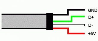
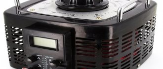
4-Pin computer cooler pinout
Electrical diagram of a 4-Pin cooler
As befits such a device, the fan in question has an electrical circuit. One of the common options is shown in the image below. Such an illustration may be needed when resoldering or reworking the connection method and will be useful to people who understand the structure of electronics. In addition, all four wires are marked in the picture, so there should be no problems reading the diagram.
Pinout
If you have already read our other article on the topic of pinout of a 3-Pin computer cooler, then you may know that black indicates ground, that is, zero contact, yellow and green have a voltage of 12 and 7 Volts, respectively. Now we need to consider the fourth wire.
The blue contact is the control one and is responsible for adjusting the speed of the blades. It is also called a PWM contact, or PWM (pulse width modulation). PWM is a method of controlling load power, which is carried out by applying pulses of different widths. Without using PWM, the fan will rotate constantly at maximum power - 12 Volts. If the program changes the rotation speed, the modulation itself comes into play. Pulses with a high frequency are supplied to the control contact, which does not change, only the time the fan is in the pulse winding changes. Therefore, the equipment specification specifies the range of its rotation speed. The lower value is most often tied to the minimum pulse frequency, that is, in their absence, the blades can spin even slower, if this is provided for by the system in which it operates.
As for controlling the rotation speed through the modulation under consideration, there are two options. The first occurs using a multicontroller located on the motherboard. It reads data from the thermal sensor (if we are considering a processor cooler) and then determines the optimal fan operating mode. You can configure this mode manually through the BIOS.
The second way is to intercept the controller with software, and this will be software from the motherboard manufacturer, or special software, for example SpeedFan.
The PWM contact on the motherboard can control the rotation speed of even 2 or 3-Pin coolers, only they need modification. Knowledgeable users will take the electrical circuit as an example and, without any special financial costs, complete what is necessary to ensure the transmission of impulses through this contact.
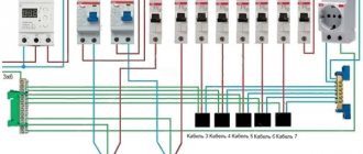
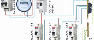
Connecting a 4-Pin cooler to the motherboard
There is not always a motherboard with four contacts for PWR_FAN, so owners of 4-Pin fans will have to be left without the speed control function, since there is simply no fourth PWM contact, as a result of which the pulses have nowhere to go. Connecting such a cooler is quite simple, you just need to find the pins on the system board.
As for the installation or dismantling of the cooler itself, a separate material is devoted to these topics on our website. We recommend that you familiarize yourself with them if you are planning to disassemble your computer.
We did not delve into the operation of the control contact, since this would be meaningless information for the average user
We only outlined its importance in the overall diagram, and also carried out a detailed pinout of all other wires
Schematic electrical diagrams, connecting devices and pinouts of connectors
Every home has a lot of computer fans: CPU coolers, video cards and PC power supplies. They can be used to replace burnt ones, or they can be connected directly to the power supply. There can be many applications for this: as a blower in hot weather, ventilating the workplace from smoke during soldering, in electronic toys, and so on.
Fans usually come in standard sizes, with 80mm and 120mm coolers being the most popular today. Their connection is also standardized, so all you need to know is the pinout of the 2, 3 and 4 pin connectors.
On modern motherboards based on the sixth or seventh generation of Intel processors, as a rule, only 4 pin connectors are soldered, and 3 pin connectors are already a thing of the past, so we will see them only in older generations of coolers and fans. As for the location of their installation - on the power supply unit, video adapter or processor, this does not matter at all since the connection is standard and the main thing here is the pinout of the connector.
Connecting the fan to the power supply
All you need to have for this operation is a thin screwdriver or tweezers, you may also need pliers, but this is optional.
We take in our hands the part of the adapter to which the wires from the Molex are connected. In this PCPlug connector we see contacts in the form of pins. This is the input of the adapter. It is this side that the adapter connects to the power supply.
As you can see, to prevent the contact pins from falling out of the connector, they are held in place by two “wings”. The pins themselves are rolled from an aluminum plate and are empty inside. They have special wings on both sides, bent in a herringbone pattern, so that they allow you to insert the pin into the connector, but not pull it out. We need to use thin tweezers or a screwdriver to bend these wings inward so that the pins can be pulled out of the connector. We need to swap the places of the black wire, which is next to the yellow one, to which the black wire from Molex and the outermost red wire are suitable.
After you pull out these two contacts, bend the wings back and insert the red wire in place of the black one, and the black wire in place of the red one. Make sure the contacts don't pop back out. All! Now the voltage on the Molex is 7 Volts.
The stated fan speed, air flow and noise level are specific to 12V power supply only. This cooler has a Molex connector. Test system:
- Processor: AMD Duron 650Mhz (launched at 650 and 748Mhz);
- Motherboard: Giga-Byte GA 7IXE4 (AMD 750 chipset);
- Memory: 128Mb PC100 SDRAM;
- Video card: ASUS v3800PRO tv in/out;
- LMD: 13.6Gb Fujitsu MPE 3136AH;
- Sound card: Creative Sound Blaster Live! Value;
5
Now unscrew the fan from the power supply
. It is secured with four bolts. You need to choose a cooler that is exactly the same size. You can do this at a computer hardware store without any problems.
The color markings on the wires that go to the power supply are different. Red wire: +5V. Black – common wires (connected to GND connectors). Yellow: +12V.
The red fan is connected to the +12V power supply (yellow power supply wire), and the black one is connected to the +5V power supply (red power supply wire). In this case, a voltage of 12V - 5V = 7V is supplied to the fan. It will work normally if the initial voltage for this particular fan is less than 7 V. If it is more (I have seen fans whose initial voltage was in the range from 9 to 11 V), then the fan will periodically twitch in attempts to start.
The yellow fan wire remains unused, since in this situation the speed sensor signals remain unclaimed.
How to be?
A factor that comes into play here is trust in a well-known brand, which was concerned about the buyer and independently measured the impeller rotation speed and air flow on the 5-volt line. True, there are not so many such brands on the market, plus the prices for their products are quite high. But this option can be safely considered, because it will satisfy the wishes of users in terms of silent operation and efficient cooling.
It is better to look for a fan for a computer power supply among products from well-known global manufacturers, such as Thermaltake, Zalman, be quiet, Noctua, Scythe. On the cooler packaging there is data on fan operation at 5 and 12 volts. Accordingly, data on speed and noise level are indicated. For example, Noctua NF-P12 – 600 rpm (12 dB). Or Thermaltake Riing 12 – 1000 rpm (18 dB). By the way, in the last example the fan is backlit.
PSU connectors
The power supply contains the main connectors (electrical connectors) previously used in old power supplies, supplying voltages of 3.3, 5 and 12 Volts. Each connector pin is one Pin.
Motherboard
connects to the power supply via a 24 Pin male connector (the so-called bus), which has undergone changes with the improvement of motherboards. Previous generations of motherboards were connected to the power supply via a 20 Pin bus.
Because of this, in order to support any type of connection to the motherboard, the connector is made in the form of a collapsible design with a 20 Pin main and 4 Pin additional power connector.
If the motherboard only needs 20 Pin, the 4 Pin connector is removed (pull down along the plastic rails) and bent to make it easy to install a 20-pin bus.
Molex 8981 connectors are used to power optical drives and other drives with a PATA (Parallel ATA) connection interface.
(by the name of the developer-manufacturer company).
SATA (Serial ATA) connection interface
for storage devices of all types.
Typically, to power storage devices
, the power supply has two special 15 Pin connectors (or there is an adapter for powering PATA HDD - SATA HDD).
Advice!
You can also connect a modern hard drive via molex, but connecting via SATA and molex at the same time is not recommended, since the HDD may not withstand the load and burn out.
Central processor
Requires power supply from a 4 or 8 Pin connector (can be detachable).
Video card
You need 6 or 8 Pin power. The connector can be dismountable to 6+2 Pin
Some modern power supplies may contain an outdated 4 Pin connector for floppy drives
, card readers, etc.
Also 3 and 4 Pin connectors are used to connect coolers
.
Work on mistakes
Not every user undertakes to change the fan for the computer power supply. Often, many owners entrust this work to service centers that specialize in such breakdowns. In fact, this is the right decision, however, judging by the reviews of the owners, there are exceptions. We are talking about installing used fans in the PSU case that have exhausted their service life in the system unit. Many users do not have a fan in their computer power supply after repair because of this.
The second problem that users may encounter is the lack of contacts in the power supply for connecting the cooler. This occurs only in cheap Chinese devices, where the economical manufacturer has soldered all the components of the power supply. In such cases, the user must also clean the contacts and solder the fan to the board (there should be no twists).
Types of cooling systems for connecting to the motherboard
Cooling units vary not only in color and size, but also in functional purpose. Basically, there is a division into processor coolers that cool the CPU in direct contact.
Next come the case fans, which were discussed above: they regulate the air flow itself passing through the system unit, and can also indirectly or directly cool individual elements of the computer.
And also don’t forget the water pump fans, which remove heat from the radiator of this device.
All of them are connected to the motherboard and controlled through it using BIOS, UEFI or operating system utilities.
Let's start with the most important fans, without which the system will be impossible to operate or will cause extreme discomfort.
Option 1: CPU cooler
The absence of a cooler on the CPU can lead to rapid overheating of this element; in addition, some BIOS subsystems will not even allow you to start loading the operating system without a cooling system installed. Connecting it to the motherboard is quite easy; you need to correctly mount it on the CPU and connect the pin wire to the appropriate connector, which is labeled on the board as follows: “CPU_FAN”.
Even for tower coolers with dual fans, one connector is enough, since such devices are equipped with a special connector that connects two fans so that they are powered via one wire.
Read more: Installing and removing a processor cooler
This is the most correct way to connect processor coolers. Of course, if you wish, you can connect them to other connectors, which will be discussed later, but then the required voltage and level of speed control will not be guaranteed. However, in models like the Cooler Master MasterAir MA620P, where there is the ability to use 3 fans, not to mention the fanciful solutions of enthusiasts, the need for connectors will only increase; such demand can be satisfied by a good motherboard with a focus on gaming.
Option 2: Case fan
Next in importance are the fans of the entire computer. Most often there are two of them - for air injection and for air exhaust - usually this amount is enough for normal PC operation without extreme loads
To install the devices, mount them on any suitable location on your computer case, then connect the wire coming from the cooling element to the connector on the motherboard labeled “CHA_FAN” or “SYS_FAN”. In this case, at the end there should be a number from “1” to the maximum number of fans that can be connected to your motherboard, including alphanumeric designations like “4A” or “3B”.
Such fans, depending on the design features of the case, can be located on the front, rear, or side cover; in addition, there are options for blowing hard drives and other system components. At the same time, you choose how this or that fan should function: by pumping air into the system unit in a certain place or, conversely, by removing it.
Option 3: Water pump fans
Water pump fans stand apart from others. It should be clarified that their number can range from 1 to 3 pieces, depending on the length of the radiator in maintenance-free water/liquid cooling systems, as well as the circuit for users in custom ones. They are connected so that they are powered from one wire, but they can also be disconnected to provide each fan with its own connector. It is necessary to separate the connection of unattended SVO and custom ones. In the case of the former, their fans should be connected in the same way as regular air fans, into the “CPU_FAN” connector.
It is better to connect custom LSS to specialized connectors labeled “W_PUMP”, “W_PUMP+” or “PUMP_FAN”, which supply higher voltage.
This article discussed common cases of connecting various types of cooling systems to the motherboard. Most often, connecting one to the other is very easy, and the connectors are labeled accordingly: “CPU_FAN”, “CHA_FAN” / “SYS_FAN” or “W_PUMP” / “PUMP_FAN”, however, it is worth understanding them and not confusing them, which can lead to failure fans or their controllers. We are glad that we were able to help you solve the problem. Describe what did not work for you. Our specialists will try to answer as quickly as possible.
Did this article help you?
- https://2shemi.ru/raspinovka-kulera-podklyuchenie-3-pin-i-4-pin-ventilyatora/
- https://infotechnica.ru/pro-sborku-i-podklyucheniya/raznyie-kulera-k-materinskim-platam/
- https://lumpics.ru/how-to-connect-a-fan-to-motherboard/
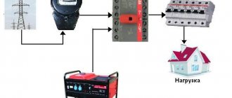
Connection procedure
Turn off the power to the computer
Simply turning off your PC using a button is not the best solution. It must be completely isolated from the electrical network, that is, unplug it from the socket or turn the switch to the “off” position.
Secure the cooler in place
To do this, you need to dismantle the side cover, install the fan in the place intended for it and secure it with bolts
It is necessary to pay attention to the indicator of the direction of rotation of its impeller (arrow on the end of the cooler). Depending on how the fan is positioned, airflow can be directed either inward (pull) or out of the computer. And this directly affects the cooling efficiency of the system unit electronics
To avoid mistakes, it is advisable to replace the cooler one-to-one, so it is not advisable to remove the faulty one before purchasing a new one.
Connection to power supply
The author does not know which fan the reader will install to replace the failed one. This may be a used product from another computer or purchased, but they all come in various modifications. Therefore, only possible options are considered below.
The photo shows the pinout of cooler connectors depending on the number of contacts. If their number does not match the computer's power supply pins, you will have to use adapters. In brackets is the color designation of the conductors according to the second option.
Wire marking
- +12 V – Kr (Zhl).
- -12 V – always black.
- Tachometer line – Zhl (Green).
- Speed control - blue.
Pinout of the computer power supply Pinout of the cooler connector
If the fan is quite noisy, then it can be powered not by 12 V, but by seven (connection to the outer terminals) or five (to the red one). The ground wire, as noted above, is always black.
Some articles give recommendations for changing the speed of rotation of the impeller using limiting resistors. Their power is about 1.2 - 2 W, and the dimensions are appropriate. It’s not quite convenient anymore. In general, this is understandable. But what criteria should be used to select the resistance value if the user with electrical equipment is, at best, only “you”? And at worst - nothing.
The author advises not to experiment and, if desired, to include a diode in the circuit. Regardless of the type, it is sure to provide a certain voltage drop on the order of 0.6 to 0.85 volts. If you need to reduce the rating even further, you can use 2 - 3 semiconductors in series. To do this, you do not need to engage in engineering calculations or consult a specialist.
Scheme
In general, a transformerless power supply is a symbiosis of a rectifier and a parametric stabilizer. Capacitor C1 for alternating current is a capacitive (reactive, i.e., not consuming energy) resistance Xc, the value of which is determined by the formula:
where f is the network frequency (50 Hz); C is the capacitance of capacitor C1, F. Then the output current of the source can be approximately determined as follows:
where Uc is the network voltage (220 V).
With a consumption current of 0.08 A, capacitance C1 should have a nominal value of 1.2 μF. Increasing it will allow you to connect a load with a large current consumption. Approximately, you can focus on 0.06 A for each microfarad of capacitance C1. I had 2.2 microfarads at 400 volts on hand.
Resistor R1 serves to discharge the capacitor after turning off the power supply. There are no special requirements for it. Nominal 330 kOhm - 1 Mohm. Power 0.5 – 2 W. In my case 620 kOhm 2 W.
Capacitor C2 serves to smooth out the ripples of the bridge-rectified voltage. Rating from 220 µF to 1000 µF with an operating voltage of at least 25 volts. I installed 470 uF at a voltage of 25 volts.
1N4007 from a used energy-saving lamp were used as rectifier diodes.
The zener diode (12 Volts) serves to stabilize the output voltage and by replacing it you can achieve almost any required voltage at the output of the power supply unit.
When assembling the circuit, you should keep in mind that the fan connection should be made correctly from the beginning. An error in soldering the fan wires in the wrong polarity will cause the fan to fail. And the connection itself (soldering) should be done in advance, since the no-load voltage at the fan connection points can be 50-100 volts. If the polarity is correct (the red wire is the positive power bus), then when connected to a 220 V network, the fan will have approximately +12 volts.
The printed circuit board is made using the LUT method. Etching was carried out with hydrogen peroxide, citric acid and table salt at the rate of 50 ml of peroxide, 2 tsp. acid and a teaspoon of salt.
In addition, I provide a diagram (maybe someone will need it) for adjusting the fan speed.
Essentially, this is a voltage regulator supplied to the fan motor. A change in voltage leads to a change in fan speed. A constant resistor R2 was specially introduced into the circuit, the purpose of which is to limit the minimum fan speed, so that even at the lowest speed, i.e. at the lowest voltage, ensure its reliable start.
Cooler pinout: connecting 3 pin and 4 pin fans
Every home has a lot of computer fans: CPU coolers, video cards and PC power supplies. They can be used to replace burnt ones, or they can be connected directly to the power supply. There can be many applications for this: as a blower in hot weather, ventilating the workplace from smoke during soldering, in electronic toys, and so on.
Fans usually come in standard sizes, with 80mm and 120mm coolers being the most popular today. Their connection is also standardized, so all you need to know is the pinout of the 2, 3 and 4 pin connectors.
On modern motherboards based on the sixth or seventh generation of Intel processors, as a rule, only 4 pin connectors are soldered, and 3 pin connectors are already a thing of the past, so we will see them only in older generations of coolers and fans. As for the location of their installation - on the power supply unit, video adapter or processor, this does not matter at all since the connection is standard and the main thing here is the pinout of the connector.
4 pin cooler wire pinout
Here the rotation speed can not only be read, but also changed. This is done using an impulse from the motherboard. It is capable of returning information to the tachogenerator in real time (the 3-pin one is incapable of this, since the sensor and controller are on the same power line).
3 pin cooler connector pinout
The most common type of fan is 3 pin. In addition to the negative and 12 volt wires, a third, “tacho” wire appears here. It sits directly on the sensor leg.
- Black wire - ground (Ground/-12V);
- Red wire - positive (+12V);
- Yellow wire - revolutions (RPM).
2 pin cooler wire pinout
The simplest cooler with two wires. The most common colors: black and red. Black - working negative of the board, red - 12 V power supply.
Here the coils create a magnetic field, which causes the rotor to spin within the magnetic field created by the magnet, and the Hall effect sensor evaluates the rotation (position) of the rotor.
How to connect a 3-pin cooler to a 4-pin
To connect a 3-pin cooler to a 4-pin connector on the motherboard in order to be able to programmatically adjust the speed, use the following diagram:
Useful: DIP chip packages
When a 3-wire fan is directly connected to a 4-pin connector on the motherboard, the fan will always rotate, because the motherboard will not have the ability to control the 3-pin fan and adjust the speed of the cooler.
Connecting the cooler to the power supply or battery
To connect to the power supply, use standard connectors, but if you need to change the number of revolutions (speed), you just need to reduce the voltage supplied to the cooler, and this is done very simply by rearranging the wires on the socket:
This way you can connect any fan, and the lower the voltage, the lower the speed, and therefore the quieter its operation. If the computer does not get very hot, but is very noisy, you can use this method.
To power it from batteries or rechargeable batteries, simply connect the plus to the red wire and the minus to the black wire of the cooler. It starts to rotate at 3 volts, the maximum speed will be somewhere around 15. You cannot increase the voltage any more - the motor windings will burn out from overheating. The current consumption will be approximately 50-100 milliamps.
PC cooler design and repair
In order to disassemble the fan, you need to remove the sticker on the side of the wires, opening access to the rubber plug, which we remove.
https://youtube.com/watch?v=_rB3ZHcTBzY
We pick up the plastic or metal half-ring with any object with a sharp end (a stationery knife, a flat-head screwdriver, etc.) and remove it from the shaft.
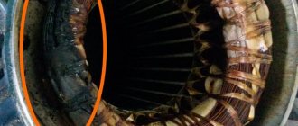
The view reveals a motor operating on direct current using a brushless principle.
An all-metal magnet is attached to the plastic base of the rotor with an impeller in a circle around the shaft, and a magnetic circuit on a copper coil is attached to the stator.
Then clean the hole under the axle and drop a little machine oil there, put it back together, install a plug (so that dust doesn’t get clogged) and continue using the much quieter fan.
All such fans have a brushless rotation mechanism: they are reliable, economical, quiet and have the ability to adjust the speed.
In modern coolers, the connectors are much smaller, where the first contact is numbered and is “minus”, the second is “plus”, the third transmits data about the current rotation speed of the impeller, and the fourth controls the rotation speed.
18— 4.56 Loading…
CLICK HERE AND OPEN
Lubrication
Having determined that replacing the computer power supply fan is not necessary, it will not be difficult for the user to take steps to clean and lubricate the cooler
However, there is one factor that all readers should pay attention to. It's about lubrication
The fact is that the hum during operation is not produced by the fan blades, but by the bearing, which, when dry, begins to distort the movement of the rotor.
The user should only use fluid oils that are capable of lubricating the bearing. However, we should not forget about high viscosity, because the lubricant must remain inside and not leak out under the influence of centrifugal force. Here it is better to use lubricant for sewing machines (analogous to the I-8 brand). In extreme cases, machine oil will do.
The principle of operation of a quenching capacitor for connecting a fan from a computer to 220 volts
Before we calculate a specific example, let's say a few words about how a quenching capacitor works in an alternating current circuit. Essentially, in this case, the capacitor works as it should. At the first half-wave, it charges, passing current and voltage. Then after charging it just "closes". Although the half-wave is not yet completed. In this case, the power supply for subsequent radioelements is limited. Further, with a reverse half-wave, everything is in the same order, but the direction of current flow and voltage through the capacitor occurs in the opposite direction. As a result, this is how voltage and current limitation occurs. The capacitor simply closes at a certain point, that's all. In fact, its closure will depend on the resistance of the consumer, on the capacitance of the capacitor, on the frequency of the alternating current. We won’t delve into the wilds, but will immediately present the final formula. Here she is.
C(uF) = (3200*I(load, A))/√(Uinput²-Uoutput²)
Let's explain the values in the formula
3200 is the proportionality coefficient, I is the current consumed by the load, Uin is the mains voltage (220 volts, although this may be less if you use a step-down transformer), Uout is the supply voltage of the load (lamp). Now that we understand what and where it comes from, let’s try to analyze the case for a specific example
Fun math
It’s better to start not with choosing a specific model or brand, but with the technical requirements that apply to the fan. Yes, such a simple computer component has a number of limitations that the user will have to put up with, because the user’s comfortable work at the computer depends on the right choice. It follows that the basic requirements are noiselessness and efficient airflow.
In most cases, the computer power supply cooling fan cannot independently regulate the speed of the impeller. By supplying 5 volts to the cooler, the power supply uses the maximum rotation speed that is characteristic of this voltage. This is where things get interesting, because the characteristics for all fans are indicated for a 12-volt line. There are few options here - trust your instincts or the recommendations of experts, because it is impossible to accurately calculate the behavior of the impeller mathematically.
PC cooler design and repair
In order to disassemble the fan, you need to remove the sticker on the side of the wires, opening access to the rubber plug, which we remove.
We pick up the plastic or metal half-ring with any object with a sharp end (a stationery knife, a flat-head screwdriver, etc.) and remove it from the shaft. The view reveals a motor operating on direct current using a brushless principle. An all-metal magnet is attached to the plastic base of the rotor with an impeller in a circle around the shaft, and a magnetic circuit on a copper coil is attached to the stator.
Then clean the hole under the axle and drop a little machine oil there, put it back together, install a plug (so that dust doesn’t get clogged) and continue using the much quieter fan.
In modern coolers, the connectors are much smaller, where the first contact is numbered and is “minus”, the second is “plus”, the third transmits data about the current rotation speed of the impeller, and the fourth controls the rotation speed.
Cooler design or how does the blower fan work?
So, there is a computer, which means there is a cooling system for some components. Including active, which involves a number of devices for forced heat removal. This means that at least several noisy fans in the computer are guaranteed. You know what types of fans for blowing electronic components are from the article Cooler: basic concepts. Now we are talking about its filling.
Where can you find the widest selection of fans for your computer or laptop? AliExpress offers the widest selection of coolers, including for any video card and a single radiator. With this choice, you can put ANY device inside your PC under cooling. Why overpay the “sellers” if you can buy the same thing right now, just by waiting a little? See for yourself right now
Foreboding
Is the fan in the computer power supply making noise? This event causes a lot of indignation from users who begin to count the costs of purchasing a new cooler. It is at this stage that there is no need to rush, the fact is that noise is not a breakdown. This is a signal to the computer owner that there are some difficulties with the fan that need to be corrected immediately. Everything is quite simple here:
- the power supply is removed and disassembled and blown away from dust;
- the fan is unscrewed and removed;
- remove the protective sticker on the cooler rotor, pour 3-4 drops of oil inside;
- the sticker is returned to its place, the power supply is assembled and installed in the computer.
The algorithm is quite simple, but very effective. There may be problems with a sticker that has lost its adhesive properties. There is no need to install it in this form; it will still fall off and rattle inside the case. It's better to install a new sticker. Where to get? Cut it out of thick tape, use a chewing gum insert, or purchase any children's sticker of similar sizes in the store.