The author of the article is a professional tutor, author of textbooks for preparing for the Unified State Exam Igor Vyacheslavovich Yakovlev
Topics of the Unified State Examination codifier: alternating current, forced electromagnetic oscillations.
Alternating current carries energy. Therefore, the issue of power in the AC circuit is extremely important.
Let and be the instantaneous values of voltage and current in a given section of the circuit. Let's take a short time interval - so small that the voltage and current will not have time to change any during this time; in other words, the values and can be considered constant during the interval.
Let a charge pass through our section over time (in accordance with the rule for choosing the sign for the current strength, a charge is considered positive if it is transferred in a positive direction, and negative otherwise). The electric field of moving charges performed work
Current power is the ratio of the work done by the electric field to the time during which this work is done:
(1)
We received exactly the same formula at one time for direct current. But in this case, power depends on time, oscillating together with current and voltage; therefore quantity (1) is also called instantaneous power
.
Due to the presence of a phase shift, the current strength and voltage in the area do not have to coincide in sign (for example, it may happen that the voltage is positive and the current strength is negative, or vice versa). Accordingly, power can be either positive or negative. Let's look at both of these cases in a little more detail.
1. Power is positive
: .
Voltage and current have the same signs. This means that the direction of the current coincides with the direction of the electric field of the charges forming the current. In this case, the energy of the section increases: it enters this section from an external circuit
(for example, the capacitor is charged).
2. Power is negative
: . Voltage and current have different signs. Therefore, the current flows against the field of moving charges that form this very current.
How can this happen? It’s very simple: the electric field that arises in the area, as it were, “outweighs” the field of moving charges and “pushes” the current against this field. In this case, the energy of the section decreases: the section gives off energy to the external circuit
(for example, the capacitor is discharging).
If you don’t quite understand what was just discussed, don’t worry - further on there will be specific examples in which you will see everything.
Current power through resistor
Let alternating current flow through a resistor with a resistance of . The voltage across the resistor, as we know, oscillates in phase with the current:
Therefore, for instantaneous power we obtain:
(2)
The graph of power (2) versus time is shown in Fig. 1. We see that the power is non-negative all the time - the resistor takes energy from the circuit, but does not return it back to the circuit.
Rice. 1. AC power through resistor
The maximum value of our power is related to the amplitudes of current and voltage by the usual formulas:
In practice, however, what is of interest is not the maximum, but the average
current power. This is understandable. Take, for example, an ordinary light bulb that is lit in your home. A current with a frequency of Hz flows through it, i.e., fluctuations in current and voltage occur per second. It is clear that over a sufficiently long time, a certain average power is released from the light bulb, the value of which is somewhere between and . Where exactly?
Look again carefully at Fig. 1. Don’t you have an intuitive feeling that the average power corresponds to the “middle” of our sinusoid and therefore takes on the value ?
This feeling is absolutely true! The way it is. Of course, we can give a mathematically strict definition of the average value of a function (in the form of some integral) and confirm our guess with direct calculation, but we don’t need this. An intuitive understanding of a simple and important fact is enough:
the average value of the square of the sine (or cosine) over the period is equal to
.
This fact is illustrated in Figure 2.
Rice. 2. The average value of the squared sine is
So, for the average value of the current power across the resistor we have:
(3)
In connection with these formulas, the so-called active
(or
effective
) values of voltage and current (in fact, these are nothing more than the
root mean square
values of voltage and current. We have already encountered this: the root mean square speed of the molecules of an ideal gas (sheet “Equation of State of an Ideal Gas”):
(4)
Formulas (3), written in terms of effective values, are completely similar to the corresponding formulas for direct current:
Therefore, if you take a light bulb, connect it first to a constant voltage source, and then to an alternating voltage source with the same effective value, then in both cases the light bulb will burn equally brightly.
The effective values (4) are extremely important for practice. It turns out that AC voltmeters and ammeters show exactly the effective values
(that's how they are designed).
Know also that the notorious volts from the outlet are the effective
value of the household power supply voltage.
Characteristics
Alternating current flows through a circuit and changes its direction with magnitude. Creates a magnetic field. Therefore, it is often called periodic sinusoidal alternating electric current. According to the law of a curved line, its value changes after a specific period of time. That's why it's called sinusoidal. Has its own parameters. The important ones are to indicate the period with frequency, amplitude and instantaneous value.
A period is the time during which the electric current changes, and then it repeats again. Frequency is the period per second. Measured in hertz, kilohertz and millihertz.
Amplitude is the maximum current value with voltage and flow efficiency over a full period. Instantaneous value is an alternating current or voltage that occurs during a specific time.
Current power through the capacitor
Let an alternating voltage be applied to the capacitor. As we know, the current through a capacitor is ahead of the voltage in phase by:
For instantaneous power we get:
A graph of instantaneous power versus time is shown in Fig. 3.
Rice. 3. AC power through capacitor
What is the average power value? It corresponds to the “middle” of the sinusoid and in this case is equal to zero! We see this now as a mathematical fact. But it would be interesting to understand from a physical point of view why the current power through the capacitor turns out to be zero.
To do this, let's draw graphs of voltage and current in the capacitor over one oscillation period (Fig. 4).
Rice. 4. Voltage across the capacitor and current through it
Let's consider all four quarters of the period sequentially.
1. First quarter
, . The tension is positive and increasing. The current is positive (flows in the positive direction), the capacitor is charged. As the charge on the capacitor increases, the current decreases.
Instantaneous power is positive: the capacitor stores energy coming from the external circuit. This energy arises due to the work of an external electric field that pushes charges onto the capacitor.
2. Second quarter
, . The tension remains positive, but is subsiding. The current changes direction and becomes negative: the capacitor is discharged against the direction of the external electric field. At the end of the second quarter, the capacitor is completely discharged.
Instantaneous power is negative: the capacitor releases energy. This energy returns to the circuit: it is used to do work against the electric field of the external circuit (the capacitor, as it were, “pushes” the charges in the direction opposite to the one in which the external field “wants” to move them).
3. Third quarter
, . The external electric field changes direction: the voltage is negative and increases in magnitude. The current is negative: the capacitor is charging in the negative direction.
The situation is completely similar to the first quarter, only the signs of voltage and current are opposite. The power is positive: the capacitor again stores energy.
4. Fourth quarter
, . The voltage is negative and decreases in magnitude. The capacitor is discharged against the external field: the current strength is positive.
Power is negative: the capacitor returns energy to the circuit. The situation is similar to the second quarter - again with the replacement by replacing the signs of current and voltage with opposite ones.
We see that the energy taken by the capacitor from the external circuit during the first quarter of the oscillation period is completely returned to the circuit during the second quarter. This process is then repeated again and again. This is why the average power consumed by a capacitor turns out to be zero.
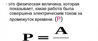
The transfer of energy w through an electrical circuit (for example, along a power line), energy dissipation, that is, the transition of electromagnetic energy into thermal energy, as well as other types of energy conversion are characterized by the intensity with which the process occurs, that is, how much energy is transmitted along the line in unit of time, how much energy is dissipated per unit of time. The intensity of energy transfer or transformation is called power p. This corresponds to a mathematical definition:
| . | (1) |
The expression for the instantaneous power value in electrical circuits has the form:
| . | (2) |
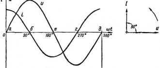
Taking the initial voltage phase as zero, and the phase shift between voltage and current as , we obtain:
| . | (3) |
So, instantaneous power has a constant component and a harmonic component, the angular frequency of which is 2 times greater than the angular frequency of voltage and current.
When the instantaneous power is negative, and this is the case (see Fig. 1), when u and i are of different signs, i.e. when the directions of voltage and current in a two-terminal network are opposite, energy is returned from the two-terminal network to the power source.
This return of energy to the source occurs due to the fact that energy is periodically stored in the magnetic and electric fields of the inductive and capacitive elements, respectively, that are part of the two-terminal network. The energy given by the source to the two-terminal network during time t is equal to .
The average value of instantaneous power over a period is called active power
.
Taking into account that , from (3) we obtain:
| . | (4) |
The active power consumed by a passive two-terminal network cannot be negative (otherwise the two-terminal network will generate energy), therefore, i.e. at the input of a passive two-terminal network. The case P = 0 is theoretically possible for a two-terminal network that does not have active resistances, but contains only ideal inductive and capacitive elements.
1. Resistor (ideal active resistance).
Here the voltage and current (see Fig. 2) are in phase, so the power is always positive, i.e. resistor consumes active power
2. Inductor (ideal inductance)
With ideal inductance, the current lags the voltage in phase by . Therefore, in accordance with (3) we can write .
Section 1-2: the energy stored in the magnetic field of the coil increases.
Section 2-3: the magnetic field energy decreases, returning to the source.
3. Capacitor (ideal capacity)
The processes for an ideal container are similar. Here . Therefore, from (3) it follows that . Thus, no active power is consumed in the inductor and capacitor (P = 0), since irreversible conversion of energy into other types of energy does not occur in them. Here only energy circulation occurs: electrical energy is stored in the magnetic field of a coil or the electric field of a capacitor for a quarter of a period, and over the next quarter of a period the energy is returned to the network. Because of this, the inductor and capacitor are called reactive elements, and their resistances XL and XC, in contrast to the active resistance R of the resistor, are called reactive.
The intensity of energy exchange is usually characterized by the highest value of the rate of energy input into the magnetic field of a coil or the electric field of a capacitor, which is called reactive power
.
In general, the expression for reactive power has the form:
| (5) |
It is positive when the current is lagging (inductive load - ) and negative when the current is leading (capacitive load - ). The unit of power as applied to the measurement of reactive power is called reactive volt-ampere
(VAR).
In particular, for the inductor we have:
, because .
.
From the latter it can be seen that the reactive power for an ideal inductor is proportional to the frequency and the maximum energy reserve in the coil. Similarly, we can obtain for an ideal capacitor:
.
Full power
In addition to the concepts of active and reactive power, the concept of apparent power is widely used in electrical engineering:
| . | (6) |
Active, reactive and apparent powers are related by the following relationship:
| . | (7) |
The ratio of active power to apparent power is called power factor
. From the above relationships it can be seen that the power factor is equal to the cosine of the shift angle between current and voltage. So,
| . | (8) |
Complex power
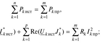
Active, reactive and apparent power can be determined using complex voltage and current images. Let , a . Then the total power complex:
| , | (9) |
where is the complex conjugate to the complex .
.
Complex power can be associated with a power triangle (see Fig. 4). Rice. 4 corresponds to (active-inductive load), for which we have:
Use of static capacitors to increase cos
As already indicated, reactive power circulates between the source and the consumer. Reactive current, without performing useful work, leads to additional losses in power equipment and, consequently, to an overestimation of its installed power. In this regard, the desire for an increase in power electrical circuits is understandable.
It should be noted that the vast majority of consumers (electric motors, electric furnaces, other various devices and appliances) as a load are of an active-inductive nature.
If you turn on capacitor C in parallel with such a load (see Fig. 5), then the total current, as can be seen from the vector diagram (Fig. 6), approaches the phase of the voltage, i.e. increases, and the total current (and therefore losses) decreases at constant active power. This is the basis for the use of capacitors to increase .
What capacitance C must be taken to increase the power factor from value to value ?
Let's break it down into active and reactive components. The current through the capacitor compensates for part of the reactive component of the load current:
| ; | (10) |
| ; | (11) |
| . | (12) |
From (11) and (12) taking into account (10) we have
,
but where does the capacity needed to increase come from:
| . | (13) |
Power balance
Power balance is a consequence of the law of conservation of energy and can serve as a criterion for the correct calculation of an electrical circuit.
a) Direct current
For any DC circuit the following relation holds:
| (14) |
This equation is a mathematical form of power balance: the total power generated by electrical energy sources is equal to the total power consumed in the circuit.
It should be noted that on the left side of (14) the terms have a “+” sign, since the active power is dissipated by resistors. On the right side of (14), the sum of the terms is greater than zero, but individual terms here may have a “-” sign, which indicates that the corresponding sources operate in the mode of energy consumers (for example, battery charge).
b) Alternating current.
From the law of conservation of energy it follows that the sum of all active powers supplied is equal to the sum of all active powers consumed, i.e.
| (15) |
In the TOE it is proven (due to the rather cumbersome nature of the derivation, we will omit this proof) that the balance is also maintained for reactive powers:
| , | (16) |
where the “+” sign refers to inductive elements, “-” - to capacitive ones.
Multiplying (16) by “j” and adding the resulting result with (15), we arrive at an analytical expression for the power balance in sinusoidal current circuits (without taking into account mutual inductance):
or
.
Literature
- Fundamentals
of circuit theory: Textbook. for universities / G.V. Zeveke, P.A. Ionkin, A.V. Netushil, S.V. Strakhov. –5th ed., revised. –M.: Energoatomizdat, 1989. -528 p. - Bessonov
L.A. Theoretical foundations of electrical engineering: Electric circuits. Textbook for students of electrical engineering, energy and instrument engineering specialties of universities. –7th ed., revised. and additional –M.: Higher. school, 1978. –528 p.
Test questions and tasks
- What is active power?
- What is reactive power, what elements is it associated with?
- What is gross power?
- Why is it necessary to strive to improve power factor?
- What is the criterion for power balance?
- An active-inductive load is connected to a voltage source, the current in which is . Determine active, reactive and apparent power.
- In a branch containing a resistor R and an inductor L connected in series, the current is I = 2 A. The voltage at the terminals of the branch is U = 100 V, and the power consumption is P = 120 W. Determine the resistances R and XL of the branch elements.
- The power consumed by a circuit consisting of a parallel-connected capacitor and resistor is P = 90 W. The current in the unbranched part of the circuit is I1=5 A, and in the branch with a resistor I2=4 A. Determine the resistances R and XC of the circuit elements.
Answer: P=250 W; Q=433 VAr; S=500 VA.
Answer: R=30 Ohm; XL=40 Ohm.
Answer: R=10 Ohm; XС=7.5 Ohm.
Current power through the coil
Let alternating voltage be applied to the coil. The current through the coil lags in phase from the voltage by:
For instantaneous power we get:
Again the average power is zero. The reasons for this are, in general, the same as in the case of a capacitor. Let's look at the graphs of voltage and current through the coil over a period (Fig. 5).
Rice. 5. Voltage on the coil and current through it
We see that during the second and fourth quarters of the period, energy enters the coil from the external circuit. In fact, voltage and current have the same signs, the current increases in magnitude; To create a current, the external electric field does work against the vortex electric field, and this work goes to increase the energy of the magnetic field of the coil.
In the first and third quarters of the period, the voltage and current have different signs: the coil returns energy to the circuit. The vortex electric field, which maintains a decreasing current, moves charges against the external electric field and thereby does positive work. How is this work accomplished? Due to the energy previously accumulated in the coil.
Thus, the energy stored in the coil during one quarter of the period is completely returned to the circuit during the next quarter. Therefore, the average power consumed by the coil is zero.
Conclusions about the three components of an alternating current circuit
Unlike direct current circuits, alternating voltage circuits have three types of power - active, reactive, apparent. Active energy, as in direct current circuits, performs useful work. Reactive - does not do anything useful, but only reduces the efficiency of the network, heats the wires, and loads the generator. Total is the sum of active and reactive, it is equal to the power of the network. The inductive component of reactive energy can be compensated by the capacitive one. In practice, in industry this is implemented in the form of capacitor units.