If such a question has to be solved by an experienced electrician, it will not be difficult for him, since finding out where the beginning and the end are is the easiest thing that can happen for him. In fact, for an experienced person this is also not difficult; you need to know the basic parameters and design rules, as well as follow safety precautions when working with electrical devices and installations, as well as high-voltage voltage, so that no unforeseen situations occur with health.
Determination of the primary and secondary windings of a transformer installation
It happens that a transformer installation has absolutely no identification marks on its body, but has copper cords that protrude from four terminals. One brood has a large copper cord, and the other has a thin one. A person who has already faced such a question will instantly be confident in what needs to be done. Since the super-thin cord is the electrical winding of the primary type, accordingly the second cord is of the secondary type.
One of the mandatory instructions is that the primary winding is connected only to a network with a voltage of 220 volts and it is wrapped with a thin cord made of copper base. This means, drawing a conclusion, we can say that the initial winding will be made of thin wire, and its resistance is 62 Ohms. Since the secondary electrical winding is made of a thick cord, the resistance is less. The secondary electrical winding can include several turns, which cannot be said about the primary winding; it is always only one.
Before connecting the transformer to the network, you need to determine the primary winding of the transformer and test its primary and secondary windings with an ohmmeter.
In step-down transformers, the resistance of the mains winding is much greater than the resistance of the secondary windings and can differ by a hundred times.
several primary windings
There can be several primary (network) windings, or a single winding can have taps if the transformer is universal and designed for use at different network voltages.
In two frame transformers on core magnetic cores, the primary windings are distributed over both frames.
protected by fuse
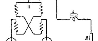
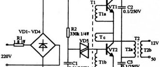
When testing transformers, you can use the diagram below. If incorrect
, the FU fuse will protect the network from short circuits and the transformer from damage.
Video: A simple way to diagnose a power transformer
When the type of power transformer is unknown, especially since we do not know its passport data, an ordinary pointer tester and a simple device in the form of an incandescent lamp come to the rescue.
How to deal with the windings of a transformer, how to properly connect it to the network and not “burn it” and how to determine the maximum currents of the secondary windings??? Many beginning radio amateurs ask themselves these and similar questions. In this article I will try to answer such questions and, using the example of several transformers (photo at the beginning of the article), to understand each of them.. I hope this article will be useful to many radio amateurs.
First, remember the general features for armored transformers
— The mains winding, as a rule, is wound first (closest to the core) and has the highest active resistance (unless it is a step-up transformer, or a transformer with anode windings).
— The network winding may have taps, or consist, for example, of two parts with taps.
— The serial connection of windings (parts of windings) for armored transformers is carried out as usual, beginning to end or terminals 2 and 3 (if, for example, there are two windings with terminals 1-2 and 3-4).
- Parallel connection of windings (only for windings with the same number of turns), the beginning is made as usual with the beginning of one winding, and the end with the end of another winding (n-n and k-k, or pins 1-3 and 2-4 - if for example there are identical windings with pins 1-2 and 3-4).
General rules for connecting secondary windings for all types of transformers.
To obtain different output voltages and load currents of windings for personal needs, different from those available on the transformer, can be obtained by various connections of the existing windings to each other. Let's consider all possible options. — Windings can be connected in series, including windings wound with wires of different diameters, then the output voltage of such a winding will be equal to the sum of the voltages of the connected windings (Utotal = U1 + U2... + Un). The load current of such a winding will be equal to the smallest load current of the available windings. For example: there are two windings with voltages of 6 and 12 volts and load currents of 4 and 2 amperes - as a result, we get a common winding with a voltage of 18 volts and a load current of 2 amperes. — Windings can be connected in parallel only if they contain the same number of turns , including those wound with wires of different diameters. The correct connection is checked like this. We connect two wires from the windings together and measure the voltage on the remaining two. If the voltage is doubled, then the connection was not made correctly, in this case we change the ends of any of the windings. If the voltage at the remaining ends is zero or so (a difference of more than half a volt is not desirable, the windings in this case will heat up at XX), feel free to connect the remaining ends together. The total voltage of such a winding does not change, and the load current will be equal to the sum of the load currents of all windings connected in parallel. (Itotal = I1 + I2… + In) . For example: there are three windings with an output voltage of 24 volts and load currents of 1 ampere each. As a result, we get a winding with a voltage of 24 volts and a load current of 3 amperes. — The windings can be connected in parallel-series (for features for parallel connection, see the paragraph above). The total voltage and current will be the same as in a series connection. For example: we have two series and three parallel connected windings (examples described above). We connect these two component windings in series. As a result, we get a common winding with a voltage of 42 volts (18+24) and a load current along the smallest winding, that is, 2 amperes. — The windings can be connected back-to-back, including those wound with wires of different diameters (also parallel and series-connected windings). The total voltage of such a winding will be equal to the difference in voltages of oppositely connected windings, the total current will be equal to the smallest winding load current. This connection is used when it is necessary to reduce the output voltage of the existing winding. Also, in order to reduce the output voltage of any winding, you can wind an additional winding on top of all the windings with a wire, preferably no smaller in diameter than the winding whose voltage needs to be reduced, so that the load current does not decrease. The winding can be wound without even disassembling the transformer, if there is a gap between the windings and the core, and it can be connected opposite the desired winding. For example: we have two windings on a transformer, one is 24 volts 3 amperes, the second is 18 volts 2 amperes. We turn them on oppositely and as a result we get a winding with an output voltage of 6 volts (24-18) and a load current of 2 amperes. But this is purely theoretical, in practice the efficiency of such a connection will be lower than if the transformer had one secondary winding. The fact is that the current flowing through the windings creates an EMF in the windings, and in a larger winding the voltage decreases in relation to the voltage XX, and at less - increases, and the greater the current flowing through the windings, the greater this effect. As a result, the total rated voltage (at rated current) will be lower.
Let's start with a small transformer, adhering to the features described above (left in the photo). We examine it carefully. All its terminals are numbered and the wires fit to the following terminals; 1, 2, 4, 6, 8, 9, 10, 12, 13, 22, 23, and 27. Next, you need to test all the terminals with an ohmmeter to determine the number of windings and draw a diagram of the transformer. The following picture emerges. Pins 1 and 2 - the resistance between them is 2.3 Ohms, 2 and 4 - between them is 2.4 Ohms, between 1 and 4 - 4.7 Ohms (one winding with a middle pin). Further 8 and 10 - resistance 100.5 Ohms (another winding). Pins 12 and 13 - 26 Ohm (another winding). Pins 22 and 23 - 1.5 Ohm (last winding). Pins 6, 9 and 27 do not communicate with other pins or with each other - these are most likely screen windings between the network and other windings. These terminals in the finished design are interconnected and attached to the housing (common wire). Let's carefully inspect the transformer again. The network winding, as we know, is wound first, although there are exceptions.
It's hard to see in the photo, so I'll duplicate it. A wire coming from the core itself is soldered to pin 8 (that is, it is closest to the core), then a wire goes to pin 10 - that is, winding 8-10 is wound first (and has the highest active resistance) and is most likely network. Now, based on the data received from the dialing, you can draw a diagram of the transformer.
All that remains is to try to connect the supposed primary winding of the transformer to a 220 volt network and check the no-load current of the transformer. To do this, we assemble the following chain.
In series with the intended primary winding of the transformer (for us these are pins 8-10), we connect an ordinary incandescent lamp with a power of 40-65 watts (for more powerful transformers 75-100 watts). In this case, the lamp will play the role of a kind of fuse (current limiter), and will protect the transformer winding from failure when connected to a 220 volt network, if we have chosen the wrong winding or the winding is not designed for a voltage of 220 volts. The maximum current flowing in this case through the winding (with a lamp power of 40 watts) will not exceed 180 milliamps. This will protect you and the transformer being tested from possible troubles.
-And in general, make it a rule that if you are not sure about the correct choice of the network winding, its switching, or the installed winding jumpers, then always make the first connection to the network with an incandescent lamp connected in series.
Being careful, we connect the assembled circuit to a 220 volt network (I have a slightly higher network voltage, or rather 230 volts). What do we see? The incandescent lamp does not light. This means that the network winding has been selected correctly and further connection of the transformer can be made without a lamp. We connect the transformer without a lamp and measure the no-load current of the transformer.
The no-load current (OC) of the transformer is measured as follows; a similar circuit is assembled that we assembled with a lamp (I won’t draw it anymore), only instead of the lamp an ammeter is turned on, which is designed to measure alternating current (carefully inspect your device for the presence of such a mode). The ammeter is first set to the maximum measurement limit, then, if there is a lot of it, the ammeter can be transferred to a lower measurement limit. Being careful, we connect to a 220 volt network, preferably through an isolation transformer. If the transformer is powerful, then at the moment the transformer is connected to the network, it is better to short-circuit either with an additional switch, or simply short-circuit with each other, since the starting current of the primary winding of the transformer exceeds the no-load current by 100-150 times and the ammeter may fail. After the transformer is connected to the network, the ammeter probes are disconnected and the current is measured.
The no-load current of the transformer should ideally be 3-8% of the rated current of the transformer. It is considered normal that the current is 5-10% of the rated value. That is, if a transformer with a calculated rated power of 100 watts, the current consumption by its primary winding is 0.45 A, then the XX current should ideally be 22.5 mA (5% of the nominal) and it is desirable that it does not exceed 45 mA (10 % of face value).
As you can see, the no-load current is a little more than 28 milliamps, which is quite acceptable (well, maybe a little too high), since this transformer looks like it has a power of 40-50 watts. We measure the open-circuit voltage of the secondary windings. It turns out at terminals 1-2-4 17.4 + 17.4 volts, terminals 12-13 = 27.4 volts, terminals 22-23 = 6.8 volts (this is at a network voltage of 230 volts). Next we need to determine the capabilities of the windings and their load currents. How it's done? If it is possible and the length of the winding wires suitable for the contacts allows, then it is better to measure the diameters of the wires (roughly up to 0.1 mm - with a caliper and accurately with a micrometer), and according to the table HERE, with an average current density of 3-4 A/mm.sq. — we find the currents that the windings are capable of producing. If it is not possible to measure the diameters of the wires, then proceed as follows. We load each of the windings in turn with an active load, which can be anything, for example, incandescent lamps of various power and voltage (an incandescent lamp with a power of 40 watts at a voltage of 220 volts has an active resistance of 90-100 Ohms in a cold state, a lamp with a power of 150 watts - 30 Ohm), resistance wires (resistors), nichrome spirals from electric stoves, rheostats, etc. We load until the voltage on the winding decreases by 10% relative to the no-load voltage. Then we measure the load current.
This current will be the maximum current that the winding is capable of delivering for a long time without overheating.
The voltage drop is conventionally accepted to be up to 10% for a constant (static) load in order to prevent the transformer from overheating. You may well take 15%, or even 20%, depending on the nature of the load. All these calculations are approximate. If the load is constant (incandescent lamps, for example, a charger), then a smaller value is taken, if the load is pulsed (dynamic), for example ULF (except for mode “A”), then a higher value can be taken, up to 15-20%.
I take the static load into account, and I succeeded; winding 1-2-4 load current (with a decrease in winding voltage by 10% relative to the no-load voltage) - 0.85 amperes (power about 27 watts), winding 12-13 (pictured above) load current 0.19-0, 2 amperes (5 watts) and winding 22-23 - 0.5 amperes (3.25 watts). The rated power of the transformer is about 36 watts (rounded to 40). Yes, I also want to talk about the resistance of the primary winding. For low-power transformers it can be tens or even hundreds of Ohms, and for high-power transformers it can be a few Ohms. Very often these questions are asked on the forum; “I measured the resistance of the primary winding of the TC250 with a multimeter, and it turned out to be 5 Ohms. Isn’t it too small for a 220 volt network, I’m afraid to plug it into the network. Tell me, is it normal?” Since all multimeters measure resistance to direct current (active resistance), there is no need to worry, because for alternating current with a frequency of 50 hertz, this winding will have a completely different resistance (inductive), which will depend on the inductance of the winding and the frequency of the alternating current. If you have something to measure inductance with, then you can calculate the winding resistance to alternating current (inductive reactance) yourself. For example; The inductance of the primary winding during the measurement was 6 H, go here and enter this data (inductance 6 H, mains frequency 50 Hz), look - it turned out to be 1884.959 (rounded up to 1885), this will be the inductive reactance of this winding for a frequency of 50 Hz . From here you can calculate the no-load current of this winding for a voltage of 220 volts - 220/1885 = 0.116 A (116 milliamps), yes, you can also add an active resistance of 5 Ohms here, that is, it will be 1890. Naturally, for a frequency of 400 Hz there will be a completely different resistance of this winding.
Other transformers are checked in the same way. The photo of the second transformer shows that the terminals are soldered to contact petals 1, 3, 4, 6, 7, 8, 10, 11, 12. After dialing, it becomes clear that the transformer has 4 windings. The first is on pins 1 and 6 (24 Ohm), the second is 3-4 (83 Ohm), the third is 7-8 (11.5 Ohm), the fourth is 10-11-12 with a tap from the middle (0.1+0.1 Ohm) .
Moreover, it is clearly visible that windings 1 and 6 are wound first (white leads), then comes winding 3-4 (black leads). 24 Ohms of active resistance of the primary winding is quite enough. For more powerful transformers, the active resistance of the winding reaches several Ohms. The second winding is 3-4 (83 Ohms), possibly boosting. Here you can measure the diameters of the wires of all windings, except for winding 3-4, the terminals of which are made of black, stranded, mounting wire.
Next we connect the transformer through an incandescent lamp. The lamp does not light up, the transformer looks like it has a power of 100-120, we measure the no-load current, it turns out 53 milliamps, which is quite acceptable. We measure the open-circuit voltage of the windings. It turns out 3-4 - 233 volts, 7-8 - 79.5 volts, and winding 10-11-12 at 3.4 volts (6.8 with the middle terminal). We load winding 3-4 until the voltage drops by 10% of the no-load voltage, and measure the current flowing through the load.
The maximum load current of this winding, as can be seen from the photograph, is 0.24 amperes. The currents of other windings are determined from the current density table, based on the diameter of the winding wire. Winding 7-8 is wound with 0.4 wire and filament with 1.08-1.1 wire. Accordingly, the currents are 0.4-0.5 and 3.5-4.0 amperes. The rated power of the transformer is about 100 watts.
There is one more transformer left. It has a contact strip with 14 contacts, the top 1, 3, 5, 7, 9, 11, 13 and bottom are even, respectively. It could switch to different mains voltages (127,220,237); it is quite possible that the primary winding has several taps, or consists of two half-windings with taps. We call, and we get the following picture: Pins 1-2 = 2.5 Ohm; 2-3 = 15.5 Ohm (this is one winding with a tap); 4-5 = 16.4 ohms; 5-6 = 2.7 Ohm (another winding with tap); 7-8 = 1.4 Ohm (3rd winding); 9-10 = 1.5 Ohm (4th winding); 11-12 = 5 Ohm (5th winding) and 13-14 (6th winding). We connect to pins 1 and 3 a network with an incandescent lamp connected in series.
The lamp burns at half intensity. We measure the voltage at the terminals of the transformer, it is 131 volts. This means they didn’t guess right and the primary winding here consists of two parts, and the connected part at a voltage of 131 volts begins to enter saturation (the no-load current increases) and therefore the lamp filament becomes hot. We connect pins 3 and 4 with a jumper, that is, two windings in series and connect the network (with a lamp) to pins 1 and 6. Hurray, the lamp is not lit. We measure the no-load current.
The no-load current is 34.5 milliamps. Here, most likely (since part of winding 2-3, and part of the second winding 4-5 have greater resistance, then these parts are designed for 110 volts, and parts of windings 1-2 and 5-6 are 17 volts each, that is, the total for one part 1278 volts) 220 volts was connected to pins 2 and 5 with a jumper on pins 3 and 4 or vice versa. But you can leave it the way we connected it, that is, all parts of the windings in series. This is only better for the transformer. That's it, the network has been found, further actions are similar to those described above.
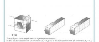
A little more about core transformers. For example, there is one like this (photo above). What are their common features?
— Rod transformers usually have two symmetrical coils, and the mains winding is divided into two coils, that is, 110 (127) volt turns are wound on one coil, and on the other. The numbering of the terminals of one coil is similar to the other; the terminal numbers on the other coil are marked (or conventionally marked) with a stroke, i.e. 1′, 2′, etc.
— The mains winding, as a rule, is wound first (closest to the core).
— The network winding may have taps, or consist of two parts (for example, one winding - terminals 1-2-3; or two parts - terminals 1-2 and 3-4).
-In a rod transformer, the magnetic flux moves along the core (in a “circle, ellipse”), and the direction of the magnetic flux of one rod will be opposite to the other, therefore, to connect the two halves of the windings in series, contacts of the same name or beginning to beginning (end to end) are connected on different coils ), i.e. 1 and 1′, the network is served on 2-2′, or 2 and 2′, the network is then served on 1 and 1′.
- For a serial connection of windings consisting of two parts on one coil - the windings are connected as usual, beginning to end or end to beginning, (n-k or k-n), that is, pin 2 and 3 (if, for example, there are 2 windings with pin numbers 1-2 and 3-4), also on the other coil. Further serial connection of the resulting two half-windings on different coils, see the paragraph above. (An example of such a connection is in the transformer diagram
). — For parallel connection of windings ( only for windings with the same number of turns ) on one coil, the connection is made as usual (n-n and k-k, or pins 1-3 and 2-4 - if, for example, there are identical windings with pins 1-2 and 3-4). For different coils, the connection is made as follows, k-n-tap and n-k-tap, or connect terminals 1-2′ and 2-1′ - if, for example, there are identical windings with terminals 1-2 and 1′-2′ .
Once again, I remind you to follow safety precautions, and it is best to have an isolation transformer at home for experiments with a voltage of 220 volts (a transformer with 220/220 volt windings for galvanic isolation from an industrial network), which will protect against electric shock if you accidentally touch the bare end of the wire .
Based on materials from the Internet
How to choose a fuse for a transformer
We calculate the fuse current in the usual way:
I is the current for which the fuse is designed (Ampere), P is the overall power of the transformer (Watt), U is the network voltage (~220 Volts).
35 / 220 = 0.16 Ampere
The closest value is 0.25 Ampere.
determination of transformer primary voltage
Circuit for measuring the no-load current (IO) of the transformer. The XX current of the transformer is usually measured to exclude the presence of short-circuited turns or to ensure that the primary winding is connected correctly.
When measuring the XX current, you need to gradually increase the supply voltage. In this case, the current should increase smoothly. When the voltage exceeds 230 volts, the current usually begins to increase more sharply. If the current begins to increase sharply at a voltage significantly less than 220 Volts, it means that either you have chosen the primary winding incorrectly, or it is faulty.
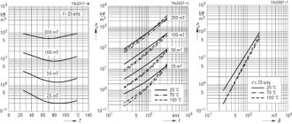
| Power, W) | Current XX (mA) |
| 5 — 10 | 10 — 200 |
| 10 -50 | 20 — 100 |
| 50 — 150 | 50 — 300 |
| 150 — 300 | 100 — 500 |
| 300 — 1000 | 200 — 1000 |
Approximate currents of XX transformers depending on power. It should be added that the currents of XX transformers, even of the same rated power, can differ greatly. The higher the induction values included in the calculation, the greater the XX current.
Connection diagram for determining the number of turns per volt.
You can select a ready-made transformer from among the unified types TN, TA, TNA, TPP and others. And if you need to wind or rewind the transformer to the desired voltage, what should you do?
Then you need to select a power transformer from an old TV that is suitable in terms of power, for example, a transformer and the like.
It must be clearly understood that the greater the number of turns in the primary winding
the greater its resistance and therefore the less heating and second, the thicker the wire, the
more current you can get
, but this depends on the size of the core - whether you can place the winding.
What do we do next if the number of turns per volt is unknown?
To do this, you need an LATR, a multimeter (tester) and a device that measures alternating current - an ammeter. At your discretion, we wind the winding over the existing one, the diameter of the wire is any; for convenience, we can simply wind it with an insulated installation wire.
Where can I get the original transformer?
The easiest way is to pick up a ready-made transformer on the radio market, if, of course, it is available in your city. There you can also agree on rewinding the transformer. But both transformers and services for rewinding them are quite expensive.
The picture shows part of a tray at a radio market where you can buy transformers in the city of Cishinau (Chisinau).
If you have some unnecessary equipment lying around in your barn or on your balcony, then there are probably transformers in it. Any dismountable network transformer is very easy to modify to suit your needs. The most important thing is that its overall power is enough.
If the power of the transformer is less than required, then under load the output voltage of the transformer may drop significantly. But this is also not a problem, since microcircuits such as TDA2030, TDA2040 and TDA2050 can operate with a significant reduction in supply voltage, namely: ±6, ±2.5 and ±4.5 Volts, respectively.
It is unlikely that the secondary windings of the found transformer will be suitable for current and voltage, but the primary winding is already designed for the voltage of the lighting network and this is the best help, since it is much easier to rewind the secondary winding than the primary.
Well, if this is a standard unified transformer, then by its name you can accurately determine the voltages and maximum permissible currents of the secondary windings. Such transformers cannot be disassembled, so before buying one, you need to check the name with the data in the directory.
At the end of the article there is a link to a reference book in which you can find detailed information about most unified transformers of Soviet and post-Soviet production.
If it is a transformer without identification marks, then the probability that it will have to be rewound will tend to 99%. It's not worth paying a lot for such a trans.
When purchasing a transformer with a ring magnetic core, you should keep in mind that not every transformer can be disassembled without damaging the primary winding.
- Suitable for replacing the secondary winding.
- It is necessary to wind the primary winding.
- It is necessary to wind the primary winding.
Return to top menu
Types of transformer windings
Depending on the relative position of the current-conducting elements, the direction of their winding and the shape of the wire section, several types of transformer windings are distinguished:
- Single or double layer cylindrical winding made of rectangular wire. The technology of its manufacture is very simple, thanks to which such coils have become widespread. The winding is thin, which reduces heating of the device. Among the disadvantages, the low strength of the structure should be highlighted.
- Multilayer cylindrical winding is similar to the previous type, but the wire is arranged in several layers. In this case, the windows of the magnetic system are filled better, but the problem of overheating appears.
- A cylindrical multilayer winding made of round wire has properties close to previous types of windings, but the disadvantages include a loss of strength as power increases.
- Helical winding with one, two or more strokes has high strength, excellent insulation and cooling. Compared to cylindrical windings, screw windings are more expensive to produce.
- The continuous winding of rectangular wire does not overheat and has a significant margin of safety.
- The multilayer foil winding is resistant to damage and fills the window of the magnetic system well, but the production technology of such coils is complex and expensive.
Transformers have six basic winding types.
On transformer diagrams, the beginning of the high voltage windings is indicated in capital letters of the Latin alphabet (A, B, C), and the same part of the low voltage wires is indicated in lowercase letters. The opposite end of the winding has a generally accepted symbol, consisting of the final three letters of the Latin alphabet - X, Y, Z for incoming voltage and x, y, z for outgoing.
Windings are distinguished by purpose:
- main ones - these include the primary and secondary windings, through which current is supplied from the network and supplied to the point of consumption;
- regulating - are taps, the main function of which is to change the voltage transformation ratio;
- auxiliary - used to meet the needs of the transformer itself.
Automated calculation of transformer winding
Choosing the right transformer is important not only when repairing the electrical network, lighting systems and control circuits. The calculation is also important for radio amateurs who want to independently make a coil for the device they are designing.
For this purpose, there are convenient calculator programs that have wide functionality and operate with various calculation methods.
Special programs will facilitate the calculation of the transformer.
- voltage supplied to the primary winding of the coil, in most cases this is for domestic use
- voltage is 220 volts;
- voltage on the secondary winding;
- secondary winding current.
The result of the calculations is presented in the form of a convenient table, which indicates values such as core parameters and rod height, wire cross-section, number of turns and winding power.
Automated calculation greatly simplifies the theoretical part of the transformer design process, allowing you to focus on important details.
No-load current measurement
If all tests have shown that the transformer is fully operational, it would not be amiss to conduct another diagnostic - for the no-load current of the transformer. Most often it is equal to 0.1-0.15 of the nominal value, that is, the current under load.
To carry out the test, the measuring device is switched to ammeter mode. Important point! The multimeter should be connected to the transformer under test in a short-circuited manner.
This is important because when electricity is supplied to the transformer winding, the current increases to several hundred times the rated current. After this, the tester probes open and the indicators are displayed on the screen. It is they that display the value of the current without load, the no-load current. In a similar way, indicators are measured on the secondary windings.
To measure voltage, a rheostat is most often connected to the transformer. If you don’t have it at hand, a tungsten spiral or a series of light bulbs can be used.
To increase the load, increase the number of bulbs or reduce the number of turns of the spiral.
As you can see, you don’t even need any special tester to check. A completely ordinary multimeter will do. It is highly desirable to have at least an approximate understanding of the operating principles and structure of transformers, but for successful measurements it is enough just to be able to switch the device to ohmmeter mode.
Source: evosnab.ru
Differences between the primary winding and the secondary winding
The type of winding can be determined by its resistance.
Determining the type of winding can be important in cases where no designations remain on the transformer. How to find out where the primary and where the secondary winding is? They are designed for different voltages. If you connect the secondary winding to a 220 V network, the device will simply burn out.
The main visual criterion by which you can determine the type of winding is the thickness of the wire soldered to its terminals. The transformer has 4 outputs: two for connecting to the network, and two more for outputting voltage. The wires that connect the primary winding to the network are small in thickness. The secondary winding is connected by wires of a fairly large cross-section.
Another sure sign that allows you to find out the type of winding is measuring the wire resistance. The resistance of the primary winding has a fairly high value when in the secondary it can be up to 1 Ohm.
Regardless of the model, the primary winding of the transformer will always be the same. On circuit diagrams it is designated by the Roman numeral I. There can be several secondary windings, their designation is II, III, IV, etc. You should not make the common mistake of calling such windings tertiary, quaternary, and so on. They all have the same rank and are called secondary.
Causes of transformer failure
- Interturn short circuit of windings
- Burnt contact on the connector
- Broken contact at the junction of the terminal with the winding
Interturn closure.
The most common cause of transformer failure is an interturn short circuit, resulting from insulation failure due to overheating. Visual signs of an interturn short circuit of a transformer are severe darkening of the high-voltage winding of the transformer and traces of carbon deposits.
The operation of the microwave is accompanied by a loud hum and a burning smell, while the transformer winding gets very hot.
Visible signs of a faulty transformer
Burnt transformer winding
Burnt out transformer
To prevent such malfunctions, it is recommended not to overheat the microwave; after long-term operation, let it “rest” for about 15-20 minutes. so she can cool down.
Burnt contact on the connector.
A common cause of a faulty transformer is a lack of contact at the junction of the terminals and connectors of the transformer. This happens as a result of poor crimping of the connectors. The place of bad contact begins to spark, the contact surface of the connector gets very hot and burns out, and eventually the contact disappears altogether. The consequences of poor crimping of connectors are shown in the photo.
A break at the junction of the terminals and the winding.
If there is no visible damage to the transformer, but the transformer does not work, there may have been a loss of contact at the junction of the winding with one of the terminals. This happens quite rarely, mainly due to poor quality factory soldering.
Microwave transformer circuit
The microwave power transformer has a primary winding of 220 Volts and two secondary windings, one of which increases from 220 Volts to
2000 Volts required to power the high-voltage magnetron circuit, the second step-down from 220 V to
3.1 V, the so-called “filament winding”, is necessary to power the magnetron anode.
Diagram of the high-voltage part of the microwave
How to test a high voltage transformer with a multimeter
The presence of contact can be checked with an ohmmeter. To check the connection, it is necessary to “ring” the resistance of its primary and secondary and filament windings. Before taking measurements, you need to disconnect all terminals from the transformer.
Primary winding test: 2 to 4 ohms. At the same time, the terminals of the primary winding should not “ring” to the transformer body. If there is a breakdown of the primary winding on the housing, the transformer is faulty.
Checking the secondary winding: from 120 to 200 Ohms. One of the terminals of the secondary winding is fixed to the transformer body, so when “testing” the secondary winding, we touch the metal body of the transformer with one of the tester probes, and the terminals of the secondary winding with the other.
Checking the filament winding: from 0.1 to 1 Ohm. If the filament winding is in good working order, there should be no breakage.
Microwave transformer winding resistance
| Circuit being measured | Resistance |
| Primary winding | from 2 to 4 ohms |
| Secondary winding | from 120 to 200 Ohm |
| Filament winding | from 0.1 to 1 Ohm |
What functions does a transformer perform?
Transformers are widely used in battery chargers.
The main function of transformers is to reduce or increase the voltage of the current supplied to them. These devices are widely used in high-voltage networks that deliver electricity from the point of generation to the end consumer.
In a modern household it is difficult to do without a current transformer. These devices are used in all types of equipment, from refrigerators to computers.
Until recently, the size and weight of household appliances were often determined precisely by the parameters of the transformer, because the basic rule was that the higher the power of the current converter, the larger and heavier it is. To see this, just compare the two types of chargers. Transformers from an old mobile phone and a modern smartphone or tablet. In the first case, we will have a small but weighty charging device, which gets noticeably hot and often breaks down. Pulse transformers are characterized by silent operation, compactness and high reliability. The principle of their operation is that the alternating voltage is first supplied to the rectifier and converted into high-frequency pulses, which are fed to a small transformer.
When repairing equipment at home, there is often a need to independently wind the transformer coil. For this purpose, prefabricated cores are used, which consist of individual plates. The parts are connected to each other by means of a lock, forming a rigid structure. Winding with wire is done using a homemade device that works on the principle of a rotator.
When creating such a transformer, you should remember: the tighter and more neatly the wire is wound, the fewer problems will arise with the operation of such a device.
The turns are separated from each other by a single layer of paper coated with glue, and the primary winding is separated from the secondary by a gap of 4-5 layers of paper. Such insulation will provide protection against breakdowns and short circuits. A correctly assembled transformer guarantees stable operation of the equipment, the absence of annoying hum and overheating.
Determination of interturn short circuit
Another common failure of transformers is interturn short circuit. It is almost impossible to check a pulse transformer for such a malfunction with just a multimeter. However, if you attract your sense of smell, attentiveness and sharp vision, the problem can well be solved.
A little theory. The wire on the transformer is insulated exclusively with its own varnish coating. If an insulation breakdown occurs, the resistance between adjacent turns remains, as a result of which the contact area heats up. That is why the first step is to carefully inspect the device for streaks, blackening, burnt paper, swelling and a burning smell.
Next, we try to determine the type of transformer. Once this is achieved, you can look at the resistance of its windings using specialized reference books. Next, switch the tester to megohmmeter mode and begin measuring the insulation resistance of the windings. In this case, the pulse transformer tester is a regular multimeter.
Each measurement should be compared with that indicated in the reference book. If there is a discrepancy of more than 50%, then the winding is faulty.
If the resistance of the windings is not indicated for one reason or another, the reference book must provide other data: the type and cross-section of the wire, as well as the number of turns. With their help, you can calculate the desired indicator yourself.
Methods for checking a transformer with a multimeter
First of all, you should check the insulation condition of the transformer. To do this, the multimeter must be switched to megger mode. After this, measure the resistance:
- between the housing and each of the windings;
- between the windings in pairs.
The voltage at which such a test should be carried out is indicated in the technical documentation for the transformer. For example, for most high-voltage models, insulation resistance measurements are prescribed to be carried out at a voltage of 1 kV.
Checking the device with a multimeter
The required resistance value can be found in the technical documentation or in the reference book.
For example, for the same high-voltage transformers it is at least 1 mOhm.
This test is not capable of detecting interturn short circuits, as well as changes in the properties of wire and core materials. Therefore, it is imperative to check the performance characteristics of the transformer, for which the following methods are used:
Not all devices perceive a voltage of 220 volts. Reduces voltage to allow the use of electrical appliances.
How to check a varistor with a multimeter and what a varistor is needed for, read.
You can familiarize yourself with the rules for checking the voltage in an outlet with a multimeter.
Check procedure
Testing a transformer begins with identifying the windings. This can be done using markings on the device. Pin numbers, as well as their type designations, should be indicated, which allows you to establish more information in reference books. In some cases there are even explanatory drawings. If the transformer is installed in some kind of electronic device, then the electronic circuit diagram of this device, as well as a detailed specification, can clarify the situation.
So, when all the conclusions are determined, it’s the tester’s turn. With its help, you can identify the two most common faults - a short circuit (to the housing or an adjacent winding) and a winding break. In the latter case, in ohmmeter mode (resistance measurement), all windings are called back one by one. If any of the measurements shows one, that is, infinite resistance, then there is a break.
There is an important nuance here. It is better to check on an analog device, since a digital one can give distorted readings due to high induction, which is especially typical for windings with a large number of turns.
Direct method (testing the circuit under load)
This is the one that first comes to mind: you need to measure the currents in the primary and secondary windings of a working device, and then, by dividing them by each other, determine the actual transformation ratio. If it corresponds to the passport, the transformer is working, if not, you need to look for a defect. This coefficient can be calculated independently if you know the voltage that the device should produce.
For example, if it says 220V/12V, then we have a step-down transformer, therefore, the current in the secondary winding should be 220/12 = 18.3 times higher than in the primary (the term “step-down” refers to voltage).
Scheme for testing a single-phase transformer by direct measurement of primary and secondary voltages using a standard transformer
The load must be connected to the secondary winding so that currents flow in the windings at least 20% of the rated values. When you turn it on, be on your guard: if you hear a crackling sound, there is a burning smell, or you see smoke or sparking, the device must be turned off immediately.
If the transformer under test has several secondary windings, then those that are not connected to the load should be short-circuited. In an open secondary coil, when the primary coil is connected to an alternating current source, high voltage may appear, which can not only damage the equipment, but also kill a person.
Serial connection of transformer windings using a battery and a multimeter
If we are talking about a high-voltage transformer, then before turning it on you need to check whether its core needs to be grounded. This is indicated by the presence of a special terminal marked with the letter “Z” or a special icon.
The direct method of checking a transformer allows you to fully assess the condition of the latter. However, it is not always possible to turn on the transformer with a load and make all the necessary measurements.
If due to safety requirements or other reasons this cannot be done, the condition of the device is checked indirectly.
Connecting the meter via transformers
Schemes for connecting meters through transformers can be divided into two groups: semi-indirect and indirect connection.
With a semi-indirect connection scheme , the meter is connected to the network only through current transformers (CTs). This scheme is usually used for medium and large enterprises that are powered by a 0.4 kV network and have an connected load of over 100 Amperes.
With an indirect connection scheme , the meter is connected to the network through current transformers (CTs) and voltage transformers (VTs). Such schemes are used, as a rule, for large enterprises that have transformer substations and other high-voltage equipment on their balance sheet that are powered from a network above 1 kV.
The transformer switching meter has 10 or 11 outputs:
As seen in
Indirect method
This method includes several tests, each of which displays the state of the device in one aspect. Therefore, it is advisable to carry out all these tests together.
Determining the reliability of winding terminal markings
To carry out this test, the multimeter must be switched to ohmmeter mode. Next, you need to “ring” all available conclusions in pairs. Between those of them that belong to different coils, the resistance will be equal to infinity. If the multimeter shows a specific value, then the terminals belong to the same coil.
You can immediately compare the measured resistance with that given in the reference book. If there is a discrepancy of more than 50%, then an interturn short circuit or partial destruction of the wire has occurred.
Connecting a transformer to a multimeter
Please note that on coils with high inductance, that is, consisting of a significant number of turns, the digital multimeter may erroneously show an overestimated resistance. In such cases, it is advisable to use an analog device.
The windings should be checked with direct current, which the transformer cannot transform.
When using an alternating voltage, an emf will be induced in other coils and it is quite possible that it will be quite high. So, if an alternating voltage of only 20 V is applied to the secondary coil of a 220/12 V step-down transformer, then a voltage of 367 V will appear at the primary terminals and if they are accidentally touched, the user will receive a strong electric shock.
Next, you need to determine which terminals should be connected to the current source and which to the load. If it is known that the transformer is a step-down transformer, then the coil with the largest number of turns and the highest resistance must be connected to the current source. With a step-up transformer the opposite is true.
All methods for measuring electric current
But there are models that have both step-down and step-up coils among the secondary coils. Then the primary coil can, with a certain degree of probability, be recognized by the following characteristics: its terminals are usually attached away from the rest, and the coil can also be located on the frame in a separate section.
The development of the Internet has made this method possible: you need to take a photo of the transformer and write a request with the attached photo and all available information (brand, etc.) to one of the online thematic forums.
Perhaps one of its participants has dealt with such devices and can tell you in detail how it needs to be connected.
If the secondary coil has intermediate taps, it is necessary to recognize its beginning and end. To do this, you need to determine the polarity of the terminals.
Determining the polarity of winding terminals
As a meter, you should use a magnetoelectric ammeter or voltmeter, the polarity of the terminals of which is known. The device must be connected to a secondary coil. It is most convenient to use those models in which the “zero” is located in the middle of the scale, but in the absence of one, the classic one with the “zero” location on the left will do.
If there are several secondary coils, the others need to be bypassed.
Checking the polarity of phase windings of AC electrical machines
A small direct current must be passed through the primary coil. A regular battery can serve as a source, but a resistor must be included in the circuit between it and the coil to prevent a short circuit. An incandescent lamp can serve as such a resistor.
There is no need to install a switch in the primary coil circuit: just follow the multimeter needle to close the circuit by touching the wire from the lamp to the coil output, and immediately open it.
If the same poles from the battery and the multimeter are connected to the terminals of the coils, that is, the polarity is the same, then the arrow on the device will move to the right.
For a multi-polar connection - to the left.
When the power is turned off, the opposite picture will be observed: with a unipolar connection, the arrow will move to the left, with a multi-polar connection - to the right.
On a device with a “zero” at the beginning of the scale, the movement of the needle to the left is more difficult to notice, since it almost immediately bounces off the limiter. Therefore you need to watch carefully.
Using the same scheme, the polarities of all other coils are checked.
A multimeter is a very necessary device for measuring current strength, which is used to identify malfunctions of certain devices. – read useful tips on choosing.
Instructions for checking diodes with a multimeter are presented.
Removing the magnetization characteristic
To be able to use this method, you need to prepare ahead of time: while the transformer is new and known to be in good working order, its so-called current-voltage characteristic (volt-ampere characteristic) is measured. This is a graph showing the dependence of the voltage at the terminals of the secondary coils on the magnitude of the magnetizing current flowing through them.
Schemes for measuring magnetization characteristics
Having opened the circuit of the primary coil (so that the results are not distorted by interference from nearby power equipment), alternating current of varying strength is passed through the secondary, measuring the voltage at its input each time.
The power of the power supply used for this must be sufficient to saturate the magnetic circuit, which is accompanied by a decrease in the slope of the saturation curve to zero (horizontal position).
Measuring instruments must belong to an electrodynamic or electromagnetic system.
Before and after the test, the magnetic circuit must be demagnetized by increasing the current in the winding in several steps and then reducing it to zero.
As you use the device, you need to take the current-voltage characteristic at certain intervals and compare it with the original one. A decrease in its steepness will indicate the appearance of an interturn short circuit.
How to check the ignition coil with a tester
Checking the ignition coil is a lengthy process consisting of external inspection and tests using measuring instruments. Reels are usually tested on special stands in service workshops or dealerships. If you need to take measurements in artisanal conditions, you usually use a multimeter - a universal device with a wide spectrum of action.
The ignition coil is located in the switch, so for testing you should bend the latched retainer and remove the cables from the switch. Then take a multimeter and set the settings necessary to check the voltage. Now you should attach one of the cables to the output of the reel, and the second to the car body.
The result of this measurement should be 12 V. If the machine has a malfunction in the electronic control system or the electrical circuit of the switch, then the multimeter will display a reading of 0 V.
Preparing for the test
Before testing the bobbins itself, a little preparation should be done. You need to purchase a multimeter (a device that can measure voltage and electrical resistance) and find the machine's user manual. Different cars may have different types of bobbins built in, and the indicators for a specific car are indicated in the passport. If the vehicle was purchased on the secondary market, it is worth trying to find the necessary data via the Internet.
To check the ignition coil you will need a multimeter with the ability to measure resistance and voltage
The indicators that should be looked for in the specified book are the resistance of the primary and secondary windings. If you couldn’t find them in the manual, then during the test it is better to be guided by the average data described in the article.
What resistance should be on the ignition coil
To determine the voltage of the device handle, it is set to a level of 200 Ohms. After this, the resistance of the primary winding is measured. The probes are applied to the “+” and “K” terminals.
For a working bobbin, numbers in the region from 0.2 to 3 ohms are considered normal. The exact numbers may vary depending on the specific type of reel and the accuracy of the multimeter. Contacts “+” and “K” allow you to get indicators in any situation.
For the primary winding, a resistance in the range from 0.4 to 2 Ohms is considered acceptable
Now the device is switched to settings of 20 kOhm. In this position, it is necessary to measure the resistance between “K” and the middle terminal of the high-voltage cable. To do this, poke the probe into the contact area (made of copper) inside the round hole for installing the high-voltage wire. Indicators on the device of a working bobbin will display from 2 to 4 kOhm.
Visual inspection
Typically, the external appearance of the reels differs in each specific model, but on each of them you can find the main parts - the box, contacts, cover and central clamp. To carry out a visual inspection, you only need to carefully look at the reel and determine its condition. If there are small cracks, chips, or scratches on the surface, then the reel is damaged. The outer box of the device is made of ebonite, which is unable to conduct current. Therefore, interruptions in the functioning of this part are usually associated with internal flaws.
Checking the primary winding
To perform testing, you need to set up a multimeter to measure electrical resistance. The contacts are then connected to the cables with plus and minus signs on the ignition bobbin.
Diagram for checking the primary and secondary windings of the ignition coil
If, after testing is completed, the multimeter displays numbers from 0.4 to 2 Ohms on the display, then the bobbin is in order and working properly. If the indicators differ from those indicated above, then the bobbin winding has broken.
How does a transformer work and what is it for?
A transformer is one of the elementary electrical devices. The principle of its operation is based on the excitation of a magnetic field and its two-way transformation.
Important! A magnetic field can only be induced on the core using alternating current. Therefore, there are no transformers operating on direct current. If it is necessary to convert direct voltage, it is first made alternating or pulsed. For example, using master oscillators.
A primary winding is wound around a single magnetic core, to which an alternating voltage with primary characteristics is supplied. An alternating voltage is induced on the remaining windings wound on the same core. The difference in the number of turns in relation to the primary determines the transmission coefficient.
Checking household step-down devices
It is worth noting the moment of checking classic step-down transformers with a multimeter tester. They can be found in almost all power supplies that reduce the input voltage from 220 Volts to the output voltage of 5-30 Volts.
The first step is to check the primary winding, which is supplied with a voltage of 220 Volts. Signs of a primary winding malfunction:
- the slightest visibility of smoke;
- the smell of burning;
- crack.
In this case, the experiment should be stopped immediately.
If everything is normal, you can proceed to measurements on the secondary windings. You can touch them only with the tester contacts (probes). If the results obtained are less than the control ones by at least 20%, then the winding is faulty.
Unfortunately, such a current block can be tested only in cases where there is a completely similar and guaranteed working block, since it is from it that the control data will be collected. It should also be remembered that when working with indicators of the order of 10 ohms, some testers may distort the results.