The power source for electrical equipment in enterprises is power transformers; most often their operation is associated with high voltage (more than 1000 V) and high currents. Therefore, their dimensions, cost, and repair costs are significant even for large-scale production. In this regard, accordingly, so that these expensive devices themselves and the electrical equipment that is powered by them are reliably protected, a whole range of protections are used. Selecting them and setting them up is quite a difficult task, so it’s worth examining each of them in detail. Of course, this only applies to large three-phase transformers at substations. To power and protect low-power transformers, a circuit breaker or fuses are sufficient. It is too expensive and unjustified to install a complete list of protections, for example, on all welding transformers used in the workshop.
Types of damage
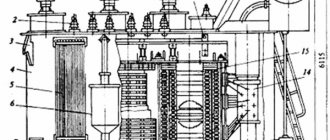
Rice.
1. Damage to transformers Due to the fact that the transformer is put into operation together with other devices, any damage to the supply line, low-voltage circuits or inside the tank is equally dangerous.
Among the current types of accidents, the following should be noted:
- Short circuit between windings;
- Short circuit of the winding to the housing;
- Interphase faults in the line;
- Interturn short circuits;
- Damage to built-in equipment;
- Overheating of connection points and electrical contacts;
- Open circuit, violation of the integrity of connection points or windings;
- Failure to fasten the iron, loosening of the sheets when the yoke ties are loosened, followed by overlap or destruction of the turns.
Measures to protect windings from overvoltage
To protect transformer windings from overvoltages, external and internal protection are used.
The first group of measures, external protection, is the use of grounded cables and surge arresters (SPDs). These measures help limit the amplitude of voltage waves approaching the transformer. Although the PUE also indicates the use of valve-type arresters as protective measures, at present they are still being widely replaced by surge arresters due to the advantages of the latter.
The main active part of the arrester (Fig. 3) consists of a set of varistors connected in series and making up the so-called “column”. Depending on the required characteristics of the arrester and its design, the limiter may consist of a single column or a number of columns connected in series or parallel. The difference between the material of varistors of surge arresters and the material of resistors of valve arresters is that nonlinear resistors of surge suppressors have an increased throughput, as well as a highly nonlinear current-voltage characteristic (volt-ampere characteristic), thanks to which it is possible to continuously and safely keep the surge arresters under voltage, which ensures high level of protection of electrical equipment. These qualities made it possible to exclude spark gaps from the arrester design.
The material of nonlinear surge arrester resistors consists mainly of an oxide and a shell in the form of glyphthalic enamel, which increases the throughput of the varistor. During the manufacturing process, zinc oxide is mixed with oxides of other metals. Varistors based on zinc oxide are a system consisting of p-n junctions connected in series and parallel. It is these p-n junctions that determine the nonlinearity of the I-V characteristic of the varistor.
Rice. 3. Surge arrester device
The surge arrester is structurally a column of varistors enclosed in a high-strength polymer housing made of high-molecular rubber (in the case of polymer insulation of the device), or a column of varistors pressed against the side surface of a fiberglass pipe located inside porcelain (in the case of porcelain insulation). In surge arresters with polymer insulation, the space between the fiberglass pipe and the column of varistors is filled with low-molecular rubber, and the pipe itself has a calculated number of holes to ensure the explosion safety of the structure during the passage of short-circuit currents. Porcelain-insulated surge arresters have membranes and sealing rubber O-rings on the end sides of the tire, and special covers with exhaust holes are installed on the flanges. The cover of the surge suppressor has a contact bolt for connection to the current-carrying busbar. The surge arrester is equipped with a base plate isolated from the ground. The internal fiberglass pipe, membranes and covers ensure the explosion-proof structure during the passage of short circuit currents.
The characteristics of various modifications of surge arresters are shown in Fig. 4.
The current-voltage characteristic of the surge arrester is shown in Fig. 5.
The appearance of surge arresters of various designs is shown in Fig. 6.
Rice. 4. Characteristics of various modifications of surge arresters.
Rice. 5. Current-voltage characteristics of surge arresters.
Rice. 6. Appearance of various surge arrester designs
Division of transformer protection into main and backup
Any type of damage in a transformer poses a potential danger to both the integrity of the equipment and the reliability of the entire power system. Therefore, it is extremely important to competently set up the operation of protections at power plants, traction and transformer substations, local transformer substations and transformer substations. For this purpose, transformer protection is conventionally divided into two categories - main and backup.
Basic protection is a type of automation that is aimed at analyzing the internal state of the transformer (windings, hardware, additional equipment). This type covers both the device itself and adjacent buses, wires, etc.
Backup protection covers those disturbances that occur outside the transformer but can directly affect its conductors and internal components. These are all kinds of overloads, short circuits and overvoltages in lines, on adjacent devices, etc.
Rice. 2. Primary and backup protections
Film protection of transformer oil
The most advanced is film protection of transformer oil. The expander is made detachable. It is filled with oil exactly to the connector and covered with an oil-resistant plastic film. The film is collected in folds. When the oil expands, the film is inflated with a bubble, but the oil does not come into contact with any gas, and its quality (degassing) is completely preserved (Fig. 5).
Fig.5. Film protection of transformer oil: Kr. Tr-ra - transformer cover; GR - gas relay; P - expander; M - oil; To the air; P - film separating oil and air
Fig.5. Thermosiphons for drying transformer oil: a - installation of a thermosiphon, b-d - designs of thermosiphons for 10 - 200 kg of silica gel adsorbent. I — transformer tank; 2 - expander; 3 - gas relay; 4 — thermosyphon filter; 5 - air dryer on. breathing tube
Oil protection from moisture is carried out using TSF thermosiphon filters (Fig. 5). TSF is a vessel filled with an adsorbent - usually silica gel or aluminum gel - a substance that absorbs moisture into its pores, but does not react with it chemically. When the silica gel is saturated with water, it is replaced with fresh one, and the wet one is dried at 400-500°C.
3% cobalt chloride is added to the adsorbent. His normal color is blue. When silica gel is saturated with moisture, the indicator turns pink. The color of the indicator can be observed through the TSF window. The amount of adsorbent is about 1% of the oil in the transformer. For powerful transformers - 0.75%.
The oil circulates through the TSF in a natural way: hot oil enters from the top of the TSF and, when cooled, falls down, giving moisture to the silica gel along the way.
Types of protections and their essence
All protections for transformers must be fast enough to turn off the dangerous mode in time. Since when extremely large electrical quantities occur, it will easily lead to destruction of insulation, metal release, fires and other unpleasant consequences.
To prevent overloads, one or another type of protection is installed on the transformer. What kind of protection is used at step-down substations and in switchgear equipment is determined by local conditions and operating conditions.
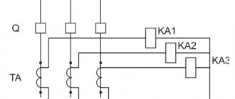
Longitudinal differential protection
The scope of differential current protection covers both the power transformer itself and the connections surrounding it, right down to current load meters. The normal operating mode of each transformer is considered to be a uniform redistribution of the load between all three phases, when the electric current in each of them is approximately the same.
Longitudinal differential protection compares the current load in all phases. Since the current is approximately the same, their geometric sum should be equal to zero. As a result of the comparison, it turns out that the current component is absent or too small for the reaction. But, as soon as a short circuit occurs in one phase or between several at once, the currents in them will no longer compensate each other, and their sum will differ from zero, and a differential cutoff will work.
Rice. 3. Example of differential protection
Relay
To prevent damage to transformers, a fairly large number of relay protections are used. However, the oil level control relay deserves special attention. This type provides for monitoring the state of the insulating environment. Structurally, the relay is a float with contacts, which is held above the contacts of the actuation circuit.
If the emergency mode leads to an oil leak and a subsequent decrease below the norm, after which a breakdown may occur, a shutdown will occur. It can be located in the main tank or have backup relay protection in the expander, which will pre-signal the start of the process.
Thermal
The basis for thermal protection in transformers is a classic thermocouple. Its location is determined by the type of device, its power and dimensions, since overheating can lead to a violation of the insulating properties and lead to thermal expansion of the oil.
The most effective placements include:
- at the top of the tank;
- at high-voltage bushings;
- in the windings.
It has two stages - the first turns on backup fans or other cooling means. The second, if the first failed to reduce the overheating below the limit value, turns off the transformer.
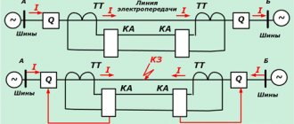
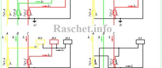
Current cut-off
Rice.
4. Example of current cut-off This type of protection is used to disconnect damage that could occur inside the transformer. It is located on the input side of the protected transformer, but the impact covers all windings from which voltage can be supplied. A special feature of its application is the power supply circuit that is used in the corresponding line.
So for three-phase circuits with an isolated neutral, the current cutoff should be installed in two phases. And when using circuits with a solidly grounded neutral, protection must be applied in each phase connection. When the transformer is turned off, there is no time delay at all.
The disadvantage of cutoff is that it only operates on high currents. Therefore, some phase-to-phase, turn-to-turn or ground faults in an isolated neutral circuit may go undetected. In practice, this is one of the simplest ways to turn off a transformer in emergency mode.
Gas protection
Gas relays, as a type of protection, have found wide application in oil-filled transformers, where transformer oil plays the role of a dielectric separating current-carrying elements and the grounded structure of the housing. During normal operation, step-down transformers do not affect the liquid dielectric, and the oil remains in a constant physical state.
But, in the event of interturn short circuits, contact of conductors with steel, or other situations inside the tank, arc burning or heating of the metal leads to local boiling of the oil. From this place the release of gases begins, which rise to the top point of the container.
Rice. 5. Example of gas protection
For the entire tank, the top point is the expansion tank, so a gas relay is installed in the connecting pipe between the expander and the transformer tank. Structurally, the gas protection is a float with two contacts. When immersed in oil, the float is in the open position. As soon as the released gases rise through the pipe, the float will fall and close the contacts, the oil transformer will turn off.
Jet protection
Used in transformers with primary and secondary windings at 110, 35, 10, 6, 3.3 kV, where it is possible to switch the voltage value under load. The on-load tap-changer is usually located in a separate tank inside the main tank, which isolates it from the high-voltage windings. Switching tap-changer positions under load can cause both normal switching phenomena and emergency ones. The latter lead to the release of oil from the tank to the conservator.
To react to such damage, jet protection is installed, since the flow of oil from the on-load tap-changer activates the measuring sensor. Next, the switch is turned off, which de-energizes the transformer windings.
Overcurrent protection
Rice.
6. Example of overcurrent protection Overcurrent protection is used to operate in response to fault currents located in close proximity to the source. This includes damage both to the windings and to the nearest substation buses, to surrounding equipment, etc.
In practice, there are a large number of options for MTZ execution:
- From internal and external short circuits;
- MTZ with combined voltage starting;
- MTZ with voltage triggering and negative sequence voltage filter;
- Negative sequence combined with a device against three-phase short circuits;
In addition to emergency modes, an overload protection mode can be installed for MTZ. To do this, the operating current is set within certain limits. The setting is selected based on the maximum load value so that the circuit breaker does not trip during normal operation.
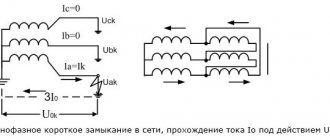
Zero sequence current protection
Rice.
7. Example of zero-sequence current protection Designed to protect a transformer from a possible short circuit of either one or two phases to ground. These are situations when in a three-phase system the load symmetry is broken and relative to the zero point the sum of the currents will no longer be equal to zero.
The equilibrium of the system will be disrupted, which will provoke a power outage after a specified period of time. Often combined with automatic reclosure, then after a few seconds the circuit breaker is reclosed, in case the short circuit has cleared itself.
Special backup protection
Special backup protection is designed for autonomous backup of overcurrent protection along current circuits. Can be used on both the high and low side of the transformer. Their action is aimed at primary and secondary maximum currents that may arise in the immediate vicinity of the protected object. The operation of the SRZ, as a rule, has a time delay relative to the main overcurrent protection on the 110 - 220 kV side.
Current step protection
Like the previous option, it is a type of MTZ, which is arranged in the key of the operating sequence for different windings. Widely used in circuits where consumers are connected to a source with large inrush currents. However, the sensitivity of maximum protection is additionally tied to voltage, which ensures that automatic shutdown is blocked in the event of powering too powerful a load, since the voltage drop does not reach the set limit.
The stages are adjusted with such a time interval that the load switches are affected after the main current protection.
Undervoltage protection
In the event of a decrease in the supply voltage, two scenarios are possible - a remote short circuit, which is recognized by other protections as a large load or the connection of too large a total load. Both options have a detrimental effect on the operation of the transformer, therefore, both in emergency mode and in case of overload, a time delay is set, after which one of the following options occurs:
- shutdown of the emergency section;
- removal of non-priority consumers from work;
- automatic switching on of reserve.
More details about this type of protection in the article
Temperature measurement with thermocouples
The principle of operation of thermal protection of a transformer is that measuring temperature with thermocouples is of great convenience when conducting heating tests, mainly in cases where there is a need to determine the temperatures of individual points of the transformer structure.
Using a thermocouple, the temperature can be measured not only on the surface of the magnetic circuit, but also at any point inside it. The highest winding temperature can also be measured using a thermocouple installed at the location where the winding is expected to be heated the most. We can say that there are no inaccessible places for measuring temperature with a thermocouple. But at the same time, measurement with thermocouples is often associated with great difficulties caused by the presence of high voltage in transformers. Therefore, installing thermocouples in windings and other energized components is not always possible, since it is associated with danger for operating personnel during testing of the transformer.
Thermocouples can be widely used in measuring the temperature of magnetic cores and other grounded components of transformers. You just need to make sure that the thermocouple wires along their path are sufficiently distant from the current-carrying parts of the transformer. Installing thermocouples in the winding (even on insulation) in the presence of high voltage is practically impossible.
In cases where this is caused by a special need, measuring the temperature of the windings with thermocouples is allowed only when testing using the short circuit method. In this case, the possibility of maintenance personnel touching the measuring device must be excluded.
To ensure the reliability of the thermocouple insulation after installing them and disassembling the transformer, before starting heating tests, the transformer insulation should be tested with applied and induced voltages 30-40% greater than what will be during testing.
A thermocouple consists of two conductors of dissimilar metals. When the junction of both conductors is heated, e.m. is formed. d.s., the value of which depends on the metals used and the heating temperature of the junction.
In table 9-3 is given e. d.s. thermocouples made from a junction of different conductors. When testing transformers, thermocouples made of constantan and K-Cu copper conductors with a diameter of 0.4–0.7 mm and a length of 5–20 m, well insulated from each other with paper, silk or other insulation, are usually used.
| Thermocouple conductor material | Electromotive force at 100° C, mV |
| Platinum - platinum radium | 0,64 |
| Constantam - silver | 4,0 |
| Konstantin—copper | 4,1 |
| Constantam—steel | 5,3 |
| Constantan-chromonickel | 5,6 |
| Bismuth—antimony | 10 |